Solutions to Homework Questions 4
Solutions to Homework Questions 4
Solutions to Homework Questions 4

Create successful ePaper yourself
Turn your PDF publications into a flip-book with our unique Google optimized e-Paper software.
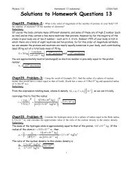
Physics 112 <strong>Homework</strong> 4 (solutions) (2004 Fall)<br />
<strong>Solutions</strong> <strong>to</strong> <strong>Homework</strong> <strong>Questions</strong> 4<br />
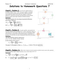
Chapt18, Problem-1: A battery having an emf of 9.00 V delivers 117 mA when connected <strong>to</strong> a<br />
72.0-! load. Determine the internal resistance of the battery.<br />
Solution:<br />
From !V = IR+ ( r ), the internal resistance is r = !V I<br />
" R = 9.00 V " 72.0 # = 4.92 !<br />
0.117 A<br />
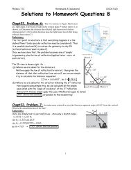
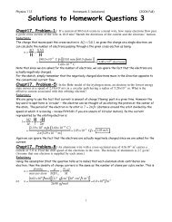
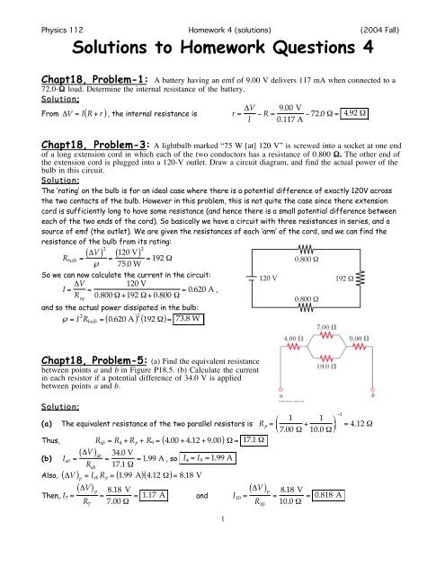
Chapt18, Problem-3: A lightbulb marked “75 W [at] 120 V” is screwed in<strong>to</strong> a socket at one end<br />
of a long extension cord in which each of the two conduc<strong>to</strong>rs has a resistance of 0.800 !. The other end of<br />
the extension cord is plugged in<strong>to</strong> a 120-V outlet. Draw a circuit diagram, and find the actual power of the<br />
bulb in this circuit.<br />
Solution:<br />
The ‘rating’ on the bulb is for an ideal case where there is a potential difference of exactly 120V across<br />
the two contacts of the bulb. However in this problem, this is not quite the case since there extension<br />
cord is sufficiently long <strong>to</strong> have some resistance (and hence there is a small potential difference between<br />
each of the two ends of the cord). So basically we have a circuit with three resistances in series, and a<br />
source of emf (the outlet). We are given the resistances of each ‘arm’ of the cord, and we can find the<br />
resistance of the bulb from its rating:<br />
( ) 2<br />
( ) 2<br />
R bulb = !V<br />
" = 120 V<br />
75.0 W = 192 #<br />
So we can now calculate the current in the circuit:<br />
I = !V<br />
120 V<br />
=<br />
R eq<br />
0.800 " +192 "+ 0.800 " = 0.620 A ,<br />
and so the actual power dissipated in the bulb:<br />
!= I 2 R bulb = ( 0.620 A ) 2 ( 192 ")= 73.8 W<br />
120 V<br />
0.800 !<br />
0.800 !<br />
192 !<br />
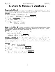
Chapt18, Problem-5: (a) Find the equivalent resistance<br />
between points a and b in Figure P18.5. (b) Calculate the current<br />
in each resis<strong>to</strong>r if a potential difference of 34.0 V is applied<br />
between points a and b.<br />
Solution:<br />
(1<br />
" 1<br />
(a) The equivalent resistance of the two parallel resis<strong>to</strong>rs is R p =<br />
7.00 ! + 1 %<br />
$<br />
' = 4.12 !<br />
# 10.0 ! &<br />
Thus, R ab = R 4 + R p + R 9 = 4.00 + 4.12 + 9.00<br />
( ) ab<br />
(b) I ab = !V<br />
Also, !V<br />
R ab<br />
( ) p<br />
= I ab R p = 1.99 A<br />
( ) p<br />
Then, I 7 = !V<br />
R 7<br />
( ) ! = 17.1 !<br />
= 34.0 V<br />
17.1 " = 1.99 A , so I 4 = I 9 = 1.99 A<br />
( )( 4.12 ")= 8.18 V<br />
= 8.18 V<br />
7.00 " = 1.17 A and I 10 = !V<br />
1<br />
( ) p<br />
R 10<br />
= 8.18 V<br />
10.0 " = 0.818 A
Physics 112 <strong>Homework</strong> 4 (solutions) (2004 Fall)<br />
Chapt18, Problem-13: Find the current<br />
in the 12-! resis<strong>to</strong>r in Figure P18.13.<br />
Solution:<br />
Clearly the first thing we need <strong>to</strong> determine is<br />
The current in the whole circuit, then we can determine how<br />
it branches. So the resis<strong>to</strong>rs in the circuit can be combined<br />
in the stages shown below <strong>to</strong> yield an equivalent<br />
resistance of R ad = 63 11 ( ) ! .<br />
a 3.0 ! I 1<br />
b<br />
I 2<br />
I 12<br />
3.0 !<br />
4.0 !<br />
12 !<br />
c<br />
e<br />
6.0 !<br />
d<br />
6.0 !<br />
2.0 !<br />
I<br />
3.0 !<br />
I 2<br />
a I 1<br />
18 V<br />
b<br />
3.0 !<br />
3.0 !<br />
e<br />
c<br />
3.0 !<br />
2.0 !<br />
d<br />
I<br />
Figure 1<br />
18 V<br />
Figure 2<br />
a<br />
3.0 !<br />
I 1<br />
b<br />
6.0 !<br />
d<br />
30<br />
— !<br />
3 ! 11<br />
a b d<br />
a<br />
63<br />
— !<br />
11<br />
d<br />
I<br />
I 2<br />
5.0 !<br />
I<br />
I<br />
18 V<br />
Figure 3<br />
18 V<br />
Figure 4<br />
( ) ad<br />
18 V<br />
Figure 5<br />
So from Figure 5, a simple application of Ohm’s law gives I = !V 18 V<br />
=<br />
R ad ( 63 11) " = 3.14 A .<br />
So now, going back <strong>to</strong> Figure 4, we know (!V) bd<br />
= IR bd = ( 3.14 A) ( 30 11 ")= 8.57 V .<br />
Going back again, this time <strong>to</strong> Figure 2, we see<br />
(!V) I 2 =<br />
bd<br />
3.0 "+ 2 .0 " = 8.57 V<br />
5.0 " = 1.71 A ,<br />
so !V<br />
So finally, from Figure 1, we can determine that I 12 = !V<br />
( ) be<br />
= I 2 R be = ( 1.71 A) 3.0 "<br />
( ) be<br />
R 12<br />
= 5.14 V<br />
12 " = 0.43 A<br />
( )= 5.14 V<br />
2
Physics 112 <strong>Homework</strong> 4 (solutions) (2004 Fall)<br />
Chapt18, Problem-19: Figure P18.19 shows a circuit<br />
diagram. Determine (a) the current, (b) the potential of<br />
wire A relative <strong>to</strong> ground, and (c) the voltage drop across<br />
the 1 500-! resis<strong>to</strong>r.<br />
Solution:<br />
(a) Applying Kirchhoff’s loop rule, as you go clockwise around the loop, gives<br />
+ 20.0 V ! ( 2000)I ! 30.0 V ! ( 2500)I + 25.0 V ! ( 500)I = 0<br />
or I = 3.00 !10 "3 A = 3.00 mA<br />
(b) Start at the grounded point and move up the left side, recording<br />
changes in potential as you go, <strong>to</strong> obtain<br />
V A =+20.0 V ! ( 2000 ")( 3.00# 10 !3 A)! 30.0 V ! ( 1000 ")( 3.00 #10 !3 A)<br />
or V A = ! 19.0 V<br />
(c) (!V) 1500<br />
= ( 1500 ")( 3.00 # 10 $3 A)= 4.50 V (The upper end is at the higher potential.)<br />
Chapt18, Problem-22: Find the current in<br />
each of the three resis<strong>to</strong>rs of Figure P18.22 (a) by the<br />
rules for resis<strong>to</strong>rs in series and parallel and (b) by the<br />
use of Kirchhoff’s rules.<br />
Solution:<br />
(a) The resis<strong>to</strong>rs can be combined as shown below <strong>to</strong> yield<br />
an equivalent of 6.6 W.<br />
6.0 !<br />
3.0 !<br />
a b c<br />
3.6 ! 3.0 !<br />
a b c<br />
a<br />
6.6 !<br />
c<br />
I 3<br />
I 9<br />
I 6<br />
I 3<br />
9.0 !<br />
I 3<br />
I 3<br />
I 3<br />
I 3<br />
12 V<br />
12 V<br />
12 V<br />
Figure 1<br />
Figure 2<br />
Figure 3<br />
(<br />
From Figure 3, I 3 = !V ) ac<br />
= 12 V<br />
R ac<br />
6.6 " = 1.8 A<br />
Then, from Figure 2, (!V) ab<br />
= I 3 R ab = ( 1.82 A) ( 3.6 ")= 6.6 V<br />
(<br />
From Figure 1, I 6 = !V ) ab<br />
6.0 " = 6.6 V<br />
6.0 " = 1.1 A (<br />
, and I 9 = !V ) ab<br />
9.0 " = 0.73 A<br />
(b) Using Figure 1 above, apply Kirchhoff’s junction rule at point a <strong>to</strong> obtain I 3 = I 6 + I 9 (1)<br />
Next, apply Kirchhoff’s loop rule <strong>to</strong> the small loop containing the 6.0 -! and 9.0 -! resis<strong>to</strong>rs <strong>to</strong> find<br />
!( 6.0)I 6 + ( 9.0)I 9 = 0 , or I 9 = ( 23)I 6 (2)<br />
Finally, apply Kirchhoff’s loop rule <strong>to</strong> the outside perimeter of Figure 1 <strong>to</strong> obtain<br />
!( 6.0)I 6 ! ( 3.0)I 3 +12 V = 0, or ( 2.0)I 6 + I 3 = 4.0 V (3)<br />
Solving equations (1), (2), and (3) simultaneously yields<br />
I 3 = 1.8 A, I 6 = 1.1 A, I 9 = 0.73 A<br />
3
Physics 112 <strong>Homework</strong> 4 (solutions) (2004 Fall)<br />
Chapt18, Problem-30: Show that ! = RC has units of time.<br />
Solution:<br />
The time constant is ! = RC. Considering the units, we find<br />
RC ! ( Ohms) ( Farads)=<br />
" Volts % "<br />
$ ' Coulombs % "<br />
$ ' =<br />
Coulombs %<br />
# Amperes&<br />
# Volts &<br />
$ '<br />
# Amperes &<br />
! Coulombs $<br />
= #<br />
" Coulombs Second<br />
&<br />
%<br />
= Second<br />
so indeed ! = RC has units of time.<br />
Chapt18, Problem-32: An uncharged capaci<strong>to</strong>r and a resis<strong>to</strong>r are connected in series <strong>to</strong> a source<br />
of emf. If E = 9.00 V, C = 20.0 µF, and R = 100 ", find (a) the time constant of the circuit, (b) the<br />
maximum charge on the capaci<strong>to</strong>r, and (c) the charge on the capaci<strong>to</strong>r after one time constant.<br />
Solution:<br />
( a ) ! = RC= ( 100 ") 20.0 # 10 $6 F<br />
2 .00 ms<br />
(b) Q max = C! = 20.0 " 10 #6 F<br />
( )= 2.00 #10 $3 s =<br />
( ) 9.00 V<br />
( )= 1.80 "10 #4 C =<br />
180 µC<br />
(c) Q = Q max ( 1 ! e ! t "<br />
)= Q ( max 1! e !" ")=<br />
Q #<br />
1! 1 & 114 µC<br />
max %<br />
$ e ( =<br />
'<br />
Chapt18, Problem-37: An electric heater is rated at 1 300 W, a <strong>to</strong>aster is rated at 1 000 W, and an<br />
electric grill is rated at 1 500 W. The three appliances are connected in parallel <strong>to</strong> a common 120-V circuit.<br />
(a) How much current does each appliance draw? (b) Is a 30.0-A circuit breaker sufficient in this situation?<br />
Explain.<br />
Solution:<br />
(a) The current drawn by each appliance is<br />
Heater: I = ! "V = 1300 W<br />
120 V = 10.8 A<br />
Toaster: I = ! "V = 1000 W<br />
120 V = 8.33 A<br />
Grill:<br />
I = ! "V = 1500 W<br />
120 V = 12.5 A<br />
( b ) If the three appliances are operated simultaneously, they will draw a <strong>to</strong>tal current of<br />
I <strong>to</strong>tal = 10.8 + 8.33 + 12.5<br />
( ) A = 31.7 A. Therefore, a 30!ampere circuit breaker is<br />
insufficient <strong>to</strong> handle the load .<br />
Chapt18, Problem-39: A heating element in a s<strong>to</strong>ve is designed <strong>to</strong> dissipate 3 000 W when<br />
connected <strong>to</strong> 240 V. (a) Assuming that the resistance is constant, calculate the current in this element if it is<br />
connected <strong>to</strong> 120 V. (b) Calculate the power it dissipates at this voltage.<br />
Solution:<br />
(<br />
From != ("V) 2 R , the resistance of the element is R = !V ) 2<br />
( ) 2<br />
When the element is connected <strong>to</strong> a 120-V source, we find that<br />
(a) I = !V R = 120 V<br />
19.2 " = 6.25 A , and<br />
(b) != ("V)I = ( 120 V) ( 6.25 A)= 750 W<br />
4<br />
" = 240 V<br />
3000 W = 19.2 #
Physics 112 <strong>Homework</strong> 4 (solutions) (2004 Fall)<br />
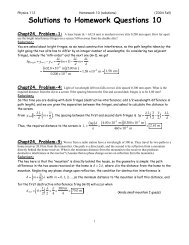
Chapt18, Problem-41: Assume that a length of axon<br />
membrane of about 10 cm is excited by an action potential.<br />
(Length excited = nerve speed x pulse duration = 50 m/s x 2.0 ms<br />
= 10 cm.) In the resting state, the outer surface of the axon wall is<br />
charged positively with K + ions and the inner wall has an equal and<br />
opposite charge of negative organic ions as shown in Figure P18.41.<br />
Model the axon as a parallel plate capaci<strong>to</strong>r and use C=!" 0 A/d and<br />
Q = C#V <strong>to</strong> investigate the charge as follows. Use typical values for<br />
a cylindrical axon of cell wall thickness d = 1.0x10 –8 m, axon<br />
radius r = 10 µm, and cell wall dielectric constant ! = 3.0.<br />
(a) Calculate the positive charge on the outside of a 10-cm piece<br />
of axon when it is not conducting an electric pulse.<br />
How many K + ions are on the outside of the axon? Is this a<br />
large charge per unit area? [Hint: Calculate the charge per unit area<br />
in terms of the number of square angstroms (Å 2 ) per electronic charge.<br />
An a<strong>to</strong>m has a cross section of about 1 Å 2 (1 Å = 10 –10 m).]<br />
(b) How much positive charge must flow through the cell membrane <strong>to</strong> reach the excited state of +30 mV<br />
from the resting state of –70 mV? How many sodium ions is this?<br />
(c) If it takes 2.0 ms for the Na + ions <strong>to</strong> enter the axon, what is the average current in the axon wall in this<br />
process?<br />
(d) How much energy does it take <strong>to</strong> raise the potential of the inner axon wall <strong>to</strong> +30 mV starting from the<br />
resting potential of –70 mV?<br />
Solution:<br />
(a) The area of each surface of this axon membrane is<br />
A = l ( 2!r )= ( 0.10 m )2! [ ( 10" 10 #6 m)<br />
]= 2! " 10 #6 m 2 , and the capacitance is<br />
( ) 2& #10 $6 m 2<br />
)<br />
C = ! " 0<br />
A<br />
d = 3.0 8.85# 10$12 C 2 N %m 2<br />
'<br />
(<br />
1.0# 10 -8 m<br />
*<br />
, = 1.67 #10 $8 F<br />
+<br />
In the resting state, the charge on the outer surface of the membrane is<br />
Q i = C (!V) i<br />
= ( 1.67 "10 #8 F) ( 70" 10 #3 V)= 1.17 " 10 #9 C $ 1.2 !10 "9 C<br />
The number of potassium ions required <strong>to</strong> produce this charge is<br />
N K<br />
+ = Q i<br />
e = 1.17 ! 10"9 C<br />
1.6! 10 -19 C = 7.3 ! 109 K + ions ,<br />
and the charge per unit area on this surface is<br />
! = Q i<br />
A = 1.17 "10 #9 C % 1 e (%<br />
2$ "10 -6 m 2 '<br />
& 1.6" 10 -19 * 10#20 m 2 ( 1 e<br />
C )<br />
'<br />
& 1 Å 2 * =<br />
) 8.6 "10 4 Å 2 = 1 e<br />
290 Å<br />
( ) 2<br />
This corresponds <strong>to</strong> a low charge density of one electronic charge per square of side 290 Å, compared <strong>to</strong> a<br />
normal a<strong>to</strong>mic spacing of one a<strong>to</strong>m per several Å 2 .<br />
(b) In the resting state, the net charge on the inner surface of the membrane is ! Q i = !1.17 " 10 !9 C ,<br />
and the net positive charge on this surface in the excited state is<br />
Q f = C (!V) f<br />
= ( 1.67 "10 #8 F) ( +30" 10 #3 V)=+5.0 " 10 #10 C<br />
The <strong>to</strong>tal positive charge which must pass through the membrane <strong>to</strong> produce the excited state is<br />
therefore<br />
!Q = Q f " Q i<br />
=+5.0 ! 10 "10 C "("1.17 !10 "9 C)= 1.67 ! 10 "9 C # 1.7 ! 10"9 C ,<br />
corresponding <strong>to</strong><br />
N Na<br />
+ = !Q 1.67 " 10 #9 C<br />
=<br />
e 1.6"10 -19 CNa + ion = 1.0 !1010 Na + ions<br />
5
Physics 112 <strong>Homework</strong> 4 (solutions) (2004 Fall)<br />
(c) If the sodium ions enter the axon in a time of !t = 2.0 ms , the average current is<br />
I = !Q<br />
!t = 1.67 "10 #9 C<br />
2.0 " 10 #3 s = 8.3 "10 #7 A =<br />
0.83 µA<br />
(d) When the membrane becomes permeable <strong>to</strong> sodium ions, the initial influx of sodium ions neutralizes<br />
the capaci<strong>to</strong>r with no required energy input. The energy input required <strong>to</strong> charge the now neutral capaci<strong>to</strong>r<br />
<strong>to</strong> the potential difference of the excited state is<br />
Chapt18, Conceptual-4: How would you connect resis<strong>to</strong>rs so that the equivalent resistance is<br />
larger than the individual resistances? Give an example involving two or three resis<strong>to</strong>rs.<br />
Solution:<br />
The resis<strong>to</strong>rs should be connected in series. For example, connecting three resis<strong>to</strong>rs of 5 ! , 7 ! , and 2 !<br />
in series gives a resultant resistance of 14 ! .<br />
Chapt18, Conceptual-5: If you have your headlights on while starting your car, why do they<br />
dim while the car is starting?<br />
Solution:<br />
The starter in the car draws a relatively large current from the battery. This large current causes a<br />
significant voltage drop across the internal resistance of the battery. As a result the terminal voltage of<br />
the battery is reduced, and the headlights dim accordingly.<br />
Chapt18, Conceptual-7: Electrical devices are often rated with a voltage and a current – for<br />
example, 120V, 5A. Batteries, however are only rated witth a voltage – for example, 1.5 V. Why?<br />
Solution:<br />
An electrical appliance has a given resistance. Thus, when it is attached <strong>to</strong> a power source with a known<br />
potential difference, a definite current will be drawn. The device can be labeled with both the voltage and<br />
the current. Batteries, however, can be applied <strong>to</strong> a number of devices. Each device will have a different<br />
resistance, so the current from the battery will vary with the device. As a result, only the voltage of the<br />
battery can be specified.<br />
Chapt18, Conceptual-10: If electrical power is transmitted over long distances, the resistance of<br />
the wores becomes significant. Why? Which mode of transmission would result in less energy loss- high<br />
current and low voltage or low current and high voltage?<br />
Solution:<br />
A wire or cable in a transmission line is thick and made of material with very low resistivity. Only when its<br />
length is very large does its resistance become significant. To transmit power over a long distance it is<br />
most efficient <strong>to</strong> use low current at high voltage, minimizing the I 2 R power loss in the transmission line.<br />
Chapt18, Conceptual-13: Why is it possible for a bird <strong>to</strong> sit on a high-voltage woire without<br />
being electrocuted?<br />
Solution:<br />
The bird is at rest on the wire whose electrical potential is also constant along its length. In order <strong>to</strong> be<br />
electrocuted, a large potential difference is required between the bird’s feet. The potential difference<br />
between the bird’s feet is <strong>to</strong>o small <strong>to</strong> harm the bird.<br />
6