738 KB
738 KB
738 KB

You also want an ePaper? Increase the reach of your titles
YUMPU automatically turns print PDFs into web optimized ePapers that Google loves.
SECTION 1F<br />
(REV.B)<br />
INSTRUCTIONS FOR<br />
URMET DOMUS DEVICE<br />
INTERCHANGEABILITY<br />
INSTRUCTIONS FOR URMET DOMUS DEVICE INTERCHANGEABILITY<br />
Download from:<br />
www.urmetdomus.com<br />
Technical Manuals area<br />
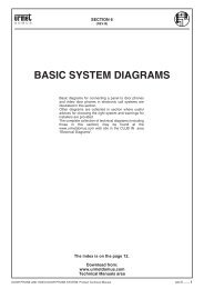
BASIC SYSTEM DIAGRAMS<br />
DOOR PHONE - VIDEO DOOR PHONE SYSTEMS: Installation Diagrams<br />
sec.1f−−−− 1
BASIC SYSTEM DIAGRAMS INSTRUCTIONS FOR URMET DOMUS DEVICE INTERCHANGEABILITY<br />
2 −−−− sec.1f DOOR PHONE - VIDEO DOOR PHONE SYSTEMS: Installation Diagrams
INTERCHANGEABLE DEVICES<br />
INTERCHANGEABLE DEVICES<br />
Some devices replace previous models and may be used as spare parts.<br />
The correspondence between versions is:<br />
(*) Not available in Italy.<br />
POWER UNITS<br />
RELAY DEVICES<br />
TRANSFORMERS<br />
APARTMENT<br />
STATIONS<br />
DOOR UNITS<br />
PREVIOUS MODEL<br />
NEW MODEL<br />
SEE PAGE<br />
786/1 786/11 23<br />
786/5A 786/15 4<br />
786/14 786/11 or 786/12 (*) 23<br />
787/4 786/4 7<br />
789 789/1A 6<br />
789 789/5B 6<br />
789/1A 789/5B 6<br />
1840/22 1090/850 7<br />
4340/20 752/20 8<br />
7073 789/1A 9<br />
7073/1 789/1A 9<br />
7073/2 789/1A 9<br />
7073/5A 789/2 16<br />
9006/1 786/11 12<br />
9006/2 786/11 12<br />
9006/3 786/3A 14<br />
9006/5 786/15 5<br />
9006/14 786/11 or 786/12 (*) 12<br />
9006/22 786/11 or 786/12 (*) 12<br />
9008/14 786/38A 14<br />
788/1 788/51 16<br />
788/5 788/52 17<br />
788/4 788/54 19<br />
788/8 788/58 18<br />
788/11 788/52 15<br />
788/21 788/52 15<br />
788/30 788/52 17<br />
4330/31 788/51 16<br />
4340/11 788/52 15<br />
4520/10 788/52 15<br />
9330 (II series) 788/52 17<br />
9332/1 788/51 16<br />
9332/5 788/52 17<br />
9332/8 788/58 18<br />
9000/20 9000/230 or 9000/110 (*) 18<br />
1201/1 Ranger 1702/1 Atlantico 20<br />
1201/10 1702/1 Atlantico 20<br />
1704/1 Sentry 1705/1 Artico 22<br />
1704/1A Sentry+ 1705/1 Artico 22<br />
1704/10 Sentry 1705/1 Artico 22<br />
1704/10A Sentry+ 1705/1 Artico 22<br />
1704/90 1704/102 22<br />
1704/955 1704/102 22<br />
4340/23 752/23 8<br />
7081/1 Vedette 1704/20 Sentry+ 20<br />
7091/1 Sentinel 1704/20 Sentry+ 20<br />
7101/1 Explorer 1704/20 Sentry+ 20<br />
5150/500 1128/500 14<br />
INSTRUCTIONS FOR URMET DOMUS DEVICE INTERCHANGEABILITY<br />
BASIC SYSTEM DIAGRAMS<br />
DOOR PHONE - VIDEO DOOR PHONE SYSTEMS: Installation Diagrams<br />
sec.1f−−−− 3
BASIC SYSTEM DIAGRAMS INSTRUCTIONS FOR URMET DOMUS DEVICE INTERCHANGEABILITY<br />
REPLACING RELAY POWER UNIT Ref. 786/5A AND Ref. 9006/5 WITH Ref. 786/15<br />
REPLACING RELAY POWER UNIT Ref. 786/5A AND Ref. 9006/5 WITH Ref. 786/15<br />
The 786/15 relay power unit can replace the following obsolete models:<br />
• Ref. 9006/5<br />
• Ref. 786/38A<br />
Follow the following diagrams according to the type of system in which the power unit is being replaced for correct connection.<br />
ELECTRONIC CALL INTERCOM SYSTEMS AND DOOR UNIT<br />
With single calls from door unit and door phones with buzzer (differential call)<br />
Ref.786/5A<br />
Ref.786/15<br />
With single calls from door unit and door phones without buzzer.<br />
Ref.786/5A<br />
Ref.786/15<br />
With single call from door unit and door phones with buzzer.<br />
Ref.786/5A<br />
Ref.786/15<br />
1 1A 1P 2 2P - + -J -P 6 ~0 PS C1 C2 ~12 SN1 SN2 ~18<br />
5 6 2 3 9 - 1 + 4 -J 7 8 ~0 PS C2 C1 PS2 ~12 SN2 SN1<br />
1 1A 1P 2 2P - + -J -P 6 ~0 PS C1 C2 ~12 SN1 SN2 ~18<br />
5 6<br />
2 3 9 - 1 + 4 -J 7 8 ~0 PS C2 C1 PS2 ~12 SN2 SN1<br />
1 1A 1P 2 2P - + -J -P 6 ~0 PS C1 C2 ~12 SN1 SN2 ~18<br />
5 6 2 3 9 - 1 + 4 -J 7 8 ~0 PS C2 C1 PS2 ~12 SN2 SN1<br />
4 −−−− sec.1f DOOR PHONE - VIDEO DOOR PHONE SYSTEMS: Installation Diagrams
REPLACING RELAY POWER UNIT Ref. 786/5A AND Ref. 9006/5 WITH Ref. 786/15<br />
TRADITIONAL CALL INTERCOM SYSTEMS AND DOOR UNIT<br />
With single calls from door unit and door phones with buzzer.<br />
Ref.786/5A 1A 1P 2 2P - -J -P 6 ~0 PS C1 C2<br />
Ref.786/15<br />
Ref.9006/5<br />
Ref.786/15<br />
1 + ~12 SN1 SN2 ~18<br />
5 6 2 3 9 - 1 + 4 -J 7 8 ~0 PS C2 C1 PS2 ~12 SN2 SN1<br />
1 1P 2 2P -6 +6 6 ~0<br />
~12 SN1 SN2 ~18<br />
5 6 2 3 9 - 1 + 4 -J 7 8 ~0 PS C2 C1 PS2 ~12 SN2 SN1<br />
INSTRUCTIONS FOR URMET DOMUS DEVICE INTERCHANGEABILITY<br />
BASIC SYSTEM DIAGRAMS<br />
DOOR PHONE - VIDEO DOOR PHONE SYSTEMS: Installation Diagrams<br />
sec.1f−−−− 5
BASIC SYSTEM DIAGRAMS INSTRUCTIONS FOR URMET DOMUS DEVICE INTERCHANGEABILITY<br />
REPLACING VIDEO DOOR PHONE POWER UNIT Ref. 789 WITH Ref. 789/1A<br />
REPLACING VIDEO DOOR PHONE POWER UNIT Ref. 789<br />
AND Ref. 789/1A WITH Ref. 789/5B<br />
REPLACING VIDEO DOOR PHONE POWER UNIT Ref. 789 WITH Ref. 789/1A<br />
The 789/1A power unit can replace the obsolete 789 model.<br />
The terminals correspond as follows:<br />
REPLACING VIDEO DOOR PHONE POWER UNIT Ref. 789 AND Ref. 789/1A WITH Ref. 789/5B<br />
The 789/5B video power unit has the following characteristics:<br />
1) It must be powered at 230 V exclusively.<br />
2) It can only be used in video door phone systems with electronic call system (it only has a PS output, no SN output).<br />
3) It can power only two video door phones in stand-by mode (V2).<br />
4) It can power up to 10 video distributors.<br />
5) It is not provided with a -J output for intercom service.<br />
POWER<br />
OUTPUTS<br />
Ref. 789 Ref. 789/1A<br />
0<br />
0<br />
-<br />
110<br />
230 230<br />
~0<br />
~0<br />
~12 ~12<br />
~A<br />
~A<br />
~B<br />
~B<br />
+6<br />
+6<br />
-6<br />
-6<br />
PS<br />
PS<br />
SN SN<br />
1/~ 1/~<br />
R1<br />
R1<br />
R2<br />
R2<br />
+TC +TC<br />
It can therefore replace the Ref. 789 and Ref. 789/1A power units only in systems with the characteristics and limitations above.<br />
In these cases, the terminals correspond as follows:<br />
SV102-1814B<br />
MAINS ~<br />
MAINS ~<br />
VOLTAGE<br />
UNIT<br />
ELECTRONIC<br />
UNIT<br />
AP<br />
SE1<br />
SE2<br />
+6J<br />
-J<br />
AP<br />
SE1<br />
SE2<br />
+6J<br />
-J<br />
POWER SUPPLY<br />
Ref.789/5B<br />
(230V)<br />
POWER SUPPLY<br />
Ref.789(230V)<br />
Ref.789/1<br />
(110/230V)<br />
6 −−−− sec.1f DOOR PHONE - VIDEO DOOR PHONE SYSTEMS: Installation Diagrams
REPLACING DOOR PHONE POWER UNIT Ref. 1840/22 WITH Ref. 1090/850<br />
REPLACING DOOR PHONE POWER UNIT Ref. 787/4 WITH Ref. 786/4<br />
REPLACING DOOR PHONE POWER UNIT Ref. 1840/22 WITH Ref. 1090/850<br />
The 1090/850 power unit can replace the obsolete 1840/22 model.<br />
The terminals correspond as follows:<br />
POWER<br />
OUTPUTS<br />
Ref. 1840/22 Ref. 1090/850<br />
0<br />
0<br />
~230<br />
~230<br />
~24 Not available<br />
~24 Not available<br />
+ (12)<br />
Vout<br />
- (12)<br />
GND<br />
REPLACING DOOR PHONE POWER UNIT Ref. 787/4 WITH Ref. 786/4<br />
The Ref. 786/4 power unit can replace the obsolete Ref. 787/4 model.<br />
The terminals correspond as follows:<br />
-<br />
-<br />
P1<br />
P2<br />
Notes<br />
(#) If a 24Vac output is needed, use a transformer with minimum output current of 0.2 Aac<br />
(∗) because the device 1840/22 actually outputs approximate 14.3 Vdc<br />
POWER<br />
OUTPUTS<br />
-<br />
-<br />
(#)<br />
(#)<br />
-<br />
Remove the<br />
jumper between<br />
terminals<br />
P1 and P2 (*)<br />
Ref. 787/4 Ref. 786/4<br />
0<br />
0<br />
110 110<br />
230 230<br />
~0<br />
~0<br />
~12 ~12<br />
+6<br />
+6<br />
-6<br />
-6<br />
-J<br />
-J<br />
PS<br />
PS<br />
PS1 PS1<br />
1/~ 1/~<br />
SN SN<br />
NA NA<br />
NC NC<br />
C<br />
C<br />
INSTRUCTIONS FOR URMET DOMUS DEVICE INTERCHANGEABILITY<br />
BASIC SYSTEM DIAGRAMS<br />
DOOR PHONE - VIDEO DOOR PHONE SYSTEMS: Installation Diagrams<br />
sec.1f−−−− 7
BASIC SYSTEM DIAGRAMS INSTRUCTIONS FOR URMET DOMUS DEVICE INTERCHANGEABILITY<br />
REPLACING DOOR PHONE TWO-CHANNEL SYSTEM POWER UNIT Ref. 4340/20<br />
WITH Ref. 752/20<br />
REPLACING TWO-CHANNEL SYSTEM DOOR PHONE APARTMENT STATION<br />
Ref. 4340/23 WITH Ref. 752/23<br />
REPLACING DOOR PHONE TWO-CHANNEL SYSTEM POWER UNIT Ref. 4340/20 WITH Ref. 752/20<br />
REPLACING TWO-CHANNEL SYSTEM DOOR PHONE APARTMENT STATION Ref. 4340/23 WITH<br />
Ref. 752/23<br />
The Ref. 752/20 power unit can replace the obsolete Ref. 4340/20 model.<br />
The Ref. 752/23 two-channel door phone apartment station replaces the Ref. 4340/23 model.<br />
The correspondence between device terminals is shown in the following diagram.<br />
PUSH<br />
BUTTONS<br />
MODULE<br />
(C4.007)<br />
TO THE<br />
FOLLOWING<br />
MODULE<br />
Microphone<br />
module<br />
Loudspeaker<br />
module<br />
~12<br />
~0<br />
~0<br />
~12<br />
G/T U4<br />
U3<br />
U2<br />
G/T U1<br />
G/T<br />
U1<br />
U2<br />
G/T2<br />
L<br />
~12<br />
~0 -<br />
+M<br />
+<br />
2<br />
1<br />
Name tag<br />
lighting<br />
To bulb<br />
transformer<br />
KOMBI FREE-HANDS PANEL<br />
AND DOOR UNIT<br />
(C4.009)<br />
twisted<br />
coupled<br />
wires<br />
To bulb<br />
transformer<br />
(C4.009)<br />
twisted<br />
coupled<br />
wires<br />
ELECTRIC LOCK ELECTRIC LOCK ELECTRIC LOCK<br />
C4.007 - Sinthesi models only:<br />
See instruction booklet provided with<br />
product for connecting terminals G/T,<br />
~0 and ~12 between modules.<br />
C4.009 - IMPORTANT Use cord pairs.<br />
VD.007 = Floor call button.<br />
VX.006 - See the instruction book<br />
provided with the product for fitting<br />
the accessory in the device.<br />
VX.014 - Dusk switch or similar device<br />
for switching lights on, where<br />
relevant.<br />
4340/27 PANEL<br />
AND DOOR UNIT<br />
TO THE FOLLOWING INDOOR SETS<br />
To bulb<br />
transformer<br />
(C4.009)<br />
twisted<br />
coupled wires<br />
(VD.007)<br />
(VD.007)<br />
Lock<br />
Release<br />
INDOOR SET<br />
Ref.4340/23<br />
POWER SUPPLY<br />
Ref.4340/20<br />
MAINS ~<br />
MAIN ~<br />
-/~<br />
+/~<br />
Name tag<br />
lighting<br />
SC101-0211B<br />
INDOOR SET<br />
Ref.752/23<br />
(VX.006)<br />
POWER SUPPLY<br />
Ref.752/20<br />
~0<br />
~12<br />
MAINS ~<br />
~<br />
(VX.014)<br />
~<br />
TRANSFORMER<br />
8 −−−− sec.1f DOOR PHONE - VIDEO DOOR PHONE SYSTEMS: Installation Diagrams
REPLACING VIDEO DOOR PHONE POWER UNIT Ref. 7073, Ref. 7073/1<br />
AND Ref. 7073/2 WITH Ref. 789/1A<br />
REPLACING VIDEO DOOR PHONE POWER UNIT Ref. 7073, Ref. 7073/1 AND Ref. 7073/2 WITH<br />
Ref. 789/1A<br />
The Ref. 789/1 A power unit replace the previous Ref. 7073, Ref. 7073/1 and Ref. 7073/2 power units in all systems except for:<br />
1) Systems with Vidicon camera: Mod. 789 power units are not provided with + LA, -LA outputs for powering lamps.<br />
2) Continuously powered systems.<br />
3) Systems with more than 20 video door phones monitors in stand-by: in this case use a 6 Vdc power unit providing suitable output current<br />
considering that the average consumption of a video door phone in stand-by is 60 mAcc.<br />
4) Systems with simultaneous operation of 2 or more video door phones: in this case, power each supplementary video door phone using local<br />
power unit Ref. 789/2.<br />
5) The Ref. 789/1 video power unit (110-230V) consists of two units connected using the specifi c wire and plugs (C).<br />
The power unit Ref. is 789/101 (110-230V).<br />
The electronic unit Ref. is 789/102.<br />
Jumpers ~0, ~A and ~12, ~B are pre-fi tted.<br />
MAINS ~<br />
MAINS ~<br />
POWER SUPPLY<br />
Ref.789/1<br />
(110/230V)<br />
VIDEO<br />
POWER SUPPLY<br />
Ref.7073 OR<br />
7073/1<br />
INSTRUCTIONS FOR URMET DOMUS DEVICE INTERCHANGEABILITY<br />
VIDEO<br />
POWER SUPPLY<br />
Ref.7073/2<br />
MAINS ~<br />
VIDEO<br />
POWER SUPPLY<br />
Ref.7073/1<br />
+<br />
CALL<br />
GENERATOR<br />
Ref.787/1<br />
MAINS ~<br />
BASIC SYSTEM DIAGRAMS<br />
DOOR PHONE - VIDEO DOOR PHONE SYSTEMS: Installation Diagrams<br />
sec.1f−−−− 9
BASIC SYSTEM DIAGRAMS INSTRUCTIONS FOR URMET DOMUS DEVICE INTERCHANGEABILITY<br />
REPLACING VIDEO DOOR PHONE POWER UNIT Ref. 7073, Ref. 7073/1<br />
AND Ref. 7073/2 WITH Ref. 789/1A<br />
SCOUT AND CAMERA SYSTEMS (CCD CAMERA ONLY)<br />
The Ref. 787/1 tone generator is not used because it is replaced by a generator inside the Ref. 789/1 A power unit.<br />
Connect jumpers SE1, ~12 during installation.<br />
POWER SUPPLY<br />
Ref.789/1A<br />
(110/230V)<br />
ELECTRONIC<br />
UNIT<br />
MAINS ~ MAINS ~<br />
VOLTAGE<br />
UNIT<br />
SENTINEL, EXPLORER AND RANGER AND CAMERA SYSTEMS (CCD CAMERA ONLY)<br />
POWER SUPPLY<br />
Ref.789/1A<br />
(110/230V)<br />
MAINS ~<br />
VOLTAGE<br />
UNIT<br />
ELECTRONIC<br />
UNIT<br />
TONE<br />
GENERATOR<br />
Ref.787/1<br />
VIDEO<br />
POWER SUPPLY<br />
Ref.7073/1<br />
VIDEO<br />
POWER SUPPLY<br />
Ref.7073/1<br />
MAINS ~<br />
LOCK<br />
RELEASE<br />
LOCK<br />
RELEASE<br />
SV102-0583A<br />
CCD TV CAMERA UNIT<br />
L.U.<br />
PUSH BUTTON<br />
PANEL<br />
TV CAMERA UNIT<br />
ELECTRIC<br />
LOCK<br />
SV102-0582A<br />
CCD TV CAMERA UNIT<br />
L.U.<br />
PUSH BUTTON<br />
PANEL<br />
TV CAMERA UNIT<br />
ELECTRIC<br />
LOCK<br />
10 −−−− sec.1f DOOR PHONE - VIDEO DOOR PHONE SYSTEMS: Installation Diagrams
SENTINEL, EXPLORER AND RANGER WITH SWITCHBOARD AND CAMERA SYSTEMS (CCD CAMERA<br />
ONLY)<br />
Cut the existing jumpers between terminals ~ A, ~0 and between ~B, ~12 of the Ref. 789/1A power unit during installation.<br />
CCD TV CAMERA UNIT<br />
PUSH BUTTON<br />
PANEL<br />
TV CAMERA UNIT<br />
ELECTRIC<br />
LOCK<br />
L.U.<br />
REPLACING VIDEO DOOR PHONE POWER UNIT Ref. 7073, Ref. 7073/1<br />
AND Ref. 7073/2 WITH Ref. 789/1A<br />
LOCK<br />
RELEASE<br />
SINGLES COMMONS<br />
STANDARD<br />
HOUSE<br />
SWITCHBOARD<br />
POWER SUPPLY Ref.786/3<br />
MAINS ~<br />
MAINS ~<br />
VIDEO<br />
POWER SUPPLY<br />
Ref.7073/1<br />
MAINS ~<br />
SV102-0584A<br />
POWER SUPPLY<br />
Ref.789/1A (110/230V)<br />
ELECTRONIC<br />
UNIT<br />
VOLTAGE<br />
UNIT<br />
NOTE<br />
INSTRUCTIONS FOR URMET DOMUS DEVICE INTERCHANGEABILITY<br />
SENTINEL, EXPLORER AND RANGER AND CAMERA SYSTEMS (VIDICON CAMERA)<br />
The Ref. 789/1A power unit is not provided with +LA and -LA outputs. An auxiliary ~24 V transformer, minimum 24 W (not included), and<br />
Ref. 788/5 control relay is needed to power the lights.<br />
POWER SUPPLY<br />
Ref.789/1<br />
(110/230V)<br />
SV102-0655A<br />
MAINS ~<br />
VOLTAGE<br />
UNIT<br />
ELECTRONIC<br />
UNIT<br />
VIDEO<br />
POWER SUPPLY<br />
Ref.7073/1<br />
MAINS ~<br />
VIDICON TYPE<br />
TV CAMERA<br />
PUSH BUTTON<br />
PANEL<br />
RELAY<br />
Ref.9332/5<br />
MAINS ~<br />
TRANSFORMER<br />
24V~ 25W<br />
LOCK<br />
RELEASE<br />
L.U.<br />
TV CAMERA UNIT<br />
ELECTRIC<br />
LOCK<br />
BASIC SYSTEM DIAGRAMS<br />
DOOR PHONE - VIDEO DOOR PHONE SYSTEMS: Installation Diagrams<br />
sec.1f−−−− 11
BASIC SYSTEM DIAGRAMS INSTRUCTIONS FOR URMET DOMUS DEVICE INTERCHANGEABILITY<br />
REPLACING DOOR PHONE POWER UNITS Ref. 9006/1, 9006/2, 9006/14 AND 9006/22 WITH<br />
Ref. 786/11<br />
The Ref. 786/11 power unit can replace the following obsolete models:<br />
• Ref. 9006/1<br />
• Ref. 9006/2<br />
• Ref. 9006/14<br />
• Ref. 9006/22<br />
The terminals correspond as follows:<br />
REPLACING DOOR PHONE POWER UNITS Ref. 9006/1, 9006/2, 9006/14<br />
AND 9006/22 WITH Ref. 786/11<br />
POWER<br />
OUTPUTS<br />
POWER<br />
OUTPUTS<br />
POWER<br />
OUTPUTS<br />
Ref. 9006/1 Ref. 786/11<br />
~0<br />
0<br />
~220 ~230<br />
~0<br />
~0<br />
~12<br />
~12<br />
+6<br />
+6<br />
-6<br />
-6<br />
-J<br />
-J<br />
Ref. 9006/2 Ref. 786/11<br />
~0<br />
0<br />
~220 ~230<br />
~0<br />
~0<br />
~12<br />
~12<br />
+6<br />
+6<br />
-6<br />
-6<br />
Ref. 9006/14 Ref. 786/11<br />
~0<br />
0<br />
~110 Not available<br />
~220<br />
~230<br />
~240 Not available<br />
~0<br />
~0<br />
~12<br />
~12<br />
~18 Not available<br />
+6<br />
+6<br />
-6<br />
-6<br />
-J<br />
-J<br />
Ref. 786/12 (∗)<br />
~110<br />
Not available<br />
Not available<br />
~0<br />
~12<br />
Not available<br />
(∗) Not available in Italy.<br />
(#) If a 18Vac output is needed, use a transformer with minimum output current of 0.5 Aac and connect as shown in the attached diagram:<br />
MAINS~<br />
MAINS~<br />
~0<br />
~12<br />
~<br />
~<br />
-J<br />
-6<br />
+6<br />
18Vca<br />
0<br />
+6<br />
-6<br />
-J<br />
Notes<br />
(#)<br />
12 −−−− sec.1f DOOR PHONE - VIDEO DOOR PHONE SYSTEMS: Installation Diagrams
REPLACING DOOR PHONE POWER UNITS Ref. 9006/1, 9006/2, 9006/14<br />
AND 9006/22 WITH Ref. 786/11<br />
POWER<br />
OUTPUTS<br />
Ref. 9006/22 Ref. 786/11<br />
~0<br />
0<br />
~110 Not available<br />
~220<br />
~230<br />
~240 Not available<br />
~0<br />
~0<br />
~12<br />
~12<br />
~24 Not available<br />
+6<br />
+6<br />
-6<br />
-6<br />
-J<br />
-J<br />
Ref. 786/12 (∗)<br />
~110<br />
Not available<br />
Not available<br />
~0<br />
~12<br />
Not available<br />
(∗) Not available in Italy.<br />
(#) If a 24Vac output is needed, use a transformer with minimum output current of 0.5 Aac and connect as shown in the attached diagram:<br />
MAINS~<br />
MAINS~<br />
~0<br />
~12<br />
~<br />
~<br />
-J<br />
-6<br />
+6<br />
24Vca<br />
0<br />
+6<br />
-6<br />
-J<br />
Notes<br />
(#)<br />
INSTRUCTIONS FOR URMET DOMUS DEVICE INTERCHANGEABILITY<br />
BASIC SYSTEM DIAGRAMS<br />
DOOR PHONE - VIDEO DOOR PHONE SYSTEMS: Installation Diagrams<br />
sec.1f−−−− 13
BASIC SYSTEM DIAGRAMS INSTRUCTIONS FOR URMET DOMUS DEVICE INTERCHANGEABILITY<br />
REPLACING SWITCHBOARD SYSTEM POWER UNIT Ref. 9006/3 WITH Ref. 786/3A<br />
REPLACING DOOR PHONE POWER UNIT Ref. 9008/14 WITH Ref. 786/38A<br />
REPLACING DOOR UNIT Ref. 5150/500 WITH Ref. 1128/500<br />
REPLACING SWITCHBOARD SYSTEM POWER UNIT Ref. 9006/3 WITH Ref. 786/3A<br />
The Ref. 786/3A power unit can replace the obsolete 9006/3 model.<br />
The terminals correspond as follows:<br />
POWER<br />
OUTPUTS<br />
REPLACING DOOR PHONE POWER UNIT Ref. 9008/14 WITH Ref. 786/38A<br />
The Ref. 786/38A power unit can replace the obsolete 9008/14 model.<br />
The terminals correspond as follows:<br />
POWER<br />
OUTPUTS<br />
Ref. 9006/3 Ref. 786/3<br />
~0<br />
0<br />
~110 Not available<br />
~220<br />
~230<br />
~240 Not available<br />
~0<br />
~0<br />
~12<br />
~12<br />
-15<br />
-15<br />
+15<br />
+15<br />
Ref. 9008/14 Ref. 786/38A<br />
~0<br />
0<br />
~110<br />
~110<br />
~220<br />
~230<br />
~240 Not available<br />
~0<br />
~0<br />
~12<br />
~12<br />
~18<br />
~18<br />
+6<br />
+6<br />
-6<br />
-6<br />
-J<br />
-J<br />
REPLACING DOOR UNIT Ref. 5150/500 WITH Ref. 1128/500<br />
Ref. 5150/500 Ref. 1128/500<br />
+<br />
+<br />
-<br />
-<br />
1<br />
1<br />
1A<br />
1A<br />
2<br />
2<br />
14 −−−− sec.1f DOOR PHONE - VIDEO DOOR PHONE SYSTEMS: Installation Diagrams
REPLACING RELAY BOXES Ref. 788/21, Ref. 788/11, Ref. 4340/11 AND Ref. 4520/10<br />
WITH Ref. 788/21<br />
REPLACING RELAY BOXES Ref. 788/21, Ref. 788/11, Ref. 4340/11 AND Ref. 4520/10 WITH<br />
Ref. 788/52<br />
The 788/52 relay box can replace the following obsolete models:<br />
• Ref. 788/11<br />
• Ref. 788/21<br />
• Ref. 4340/11<br />
• Ref. 4520/10<br />
The terminals correspond as follows:<br />
Ref. 788/21 Ref. 788/52<br />
~12 (R1-1) 12~<br />
C<br />
C<br />
CA<br />
CA<br />
0~<br />
0~<br />
6<br />
6<br />
2-7 2<br />
S1<br />
S1<br />
S2<br />
S2<br />
S3<br />
S3<br />
S4<br />
S4<br />
S5<br />
S5<br />
S6<br />
Ref. 788/11 Ref. 788/52<br />
~12 - R1 - 1 12~<br />
2 - 7<br />
2<br />
~0<br />
0~<br />
CA<br />
CA<br />
C<br />
C<br />
6<br />
6<br />
S1<br />
S1<br />
S2 - S3<br />
S6<br />
S3<br />
INSTRUCTIONS FOR URMET DOMUS DEVICE INTERCHANGEABILITY<br />
Ref. 4340/11 Ref. 788/52<br />
~12<br />
12~<br />
~0<br />
0~<br />
CA<br />
CA<br />
6<br />
6<br />
S1<br />
S1<br />
S3<br />
S3<br />
Ref. 4520/10 Ref. 788/52<br />
R1<br />
15<br />
7<br />
2<br />
2<br />
1<br />
S1<br />
S2<br />
2<br />
15<br />
S1<br />
S3<br />
BASIC SYSTEM DIAGRAMS<br />
DOOR PHONE - VIDEO DOOR PHONE SYSTEMS: Installation Diagrams<br />
sec.1f−−−− 15
BASIC SYSTEM DIAGRAMS INSTRUCTIONS FOR URMET DOMUS DEVICE INTERCHANGEABILITY<br />
REPLACING RELAY BOXES Ref. 9332/1, Ref. 4330/31 and Ref. 788/1 WITH Ref. 788/1<br />
REPLACING SUPPLEMENTARY VIDEO DOOR PHONE POWER UNIT Ref. 7073/5A<br />
WITH Ref. 789/2<br />
REPLACING RELAY BOXES Ref. 9332/1, Ref. 4330/31 AND Ref. 788/1 WITH Ref. 788/1<br />
The Ref. 788/51 relay box can replace the obsolete 9332/1 model.<br />
The terminals correspond as follows:<br />
Ref. 4330/31 Ref. 9332/1 Ref. 788/1 Ref. 788/51<br />
2P<br />
1<br />
1<br />
1<br />
2<br />
2<br />
2<br />
2<br />
2S<br />
4P<br />
4<br />
4S<br />
AP/P<br />
AP<br />
AP/S<br />
3P<br />
3<br />
3S<br />
Note : Terminals C1, C2, ~12 of relay Ref. 788/51 must be connected together by jumpers and connected to ~12.<br />
Note ∗: Terminal not present in Ref. 9332/1 and Ref. 788/51. Add power wire ~0.<br />
REPLACING SUPPLEMENTARY VIDEO DOOR PHONE POWER UNIT Ref. 7073/5A WITH<br />
Ref. 789/2<br />
The Ref. 789/2 power unit can replace the obsolete Ref. 7073/5 model.<br />
The terminals correspond as follows:<br />
Ref. 7073/5 Ref. 789/2<br />
.<br />
.<br />
.<br />
PUL/P<br />
PUL/P<br />
♦ A<br />
B<br />
POWER<br />
OUTPUTS<br />
3<br />
4<br />
5<br />
6<br />
7<br />
8<br />
9<br />
10<br />
11<br />
12<br />
13<br />
14<br />
15<br />
SN1<br />
SN2<br />
♦ SN<br />
∗<br />
0<br />
~110<br />
~230<br />
R2 in<br />
R2 out<br />
RL<br />
R1<br />
V2<br />
3<br />
4<br />
5<br />
6<br />
7<br />
8<br />
9<br />
10<br />
11<br />
12<br />
13<br />
14<br />
15<br />
SN1<br />
SN2<br />
C1<br />
C2<br />
~12<br />
~0<br />
3<br />
4<br />
5<br />
6<br />
7<br />
8<br />
9<br />
10<br />
11<br />
12<br />
13<br />
14<br />
15<br />
SN1<br />
SN2<br />
C1<br />
C2<br />
~12<br />
~0<br />
0<br />
Not available<br />
~230<br />
R2 in<br />
R2 out<br />
RL<br />
R1<br />
V2<br />
16 −−−− sec.1f DOOR PHONE - VIDEO DOOR PHONE SYSTEMS: Installation Diagrams
REPLACING RELAY BOX Ref. 9332/5 AND Ref. 788/5 WITH Ref. 788/52<br />
REPLACING RELAY BOX Ref. 9330 (II SERIES) AND Ref. 788/30 WITH Ref. 788/52<br />
REPLACING RELAY BOX Ref. 9332/5 AND Ref. 788/5 WITH Ref. 788/52<br />
The Ref. 788/52 relay box can replace the obsolete 9332/5 and 788/5 model.<br />
The terminals correspond as follows:<br />
RELAY<br />
CONTACTS<br />
Ref. 9332/5 Ref. 788/5<br />
14<br />
14<br />
15<br />
15<br />
1<br />
1<br />
2<br />
2<br />
3<br />
3<br />
4<br />
4<br />
5<br />
5<br />
6<br />
6<br />
Ref. 788/52<br />
REPLACING RELAY BOX Ref. 9330 (II SERIES) AND Ref. 788/30 WITH Ref. 788/52<br />
The Ref. 788/52 relay box can replace the obsolete 9330 II series model (which is not provided with a 150 ohm resistor in series with terminal<br />
12) and 788/30 model.<br />
The terminals correspond as follows:<br />
RELAY<br />
CONTACTS<br />
Ref. 9330 (II series) Ref. 788/30<br />
14<br />
14<br />
15<br />
15<br />
1<br />
1<br />
2<br />
2<br />
3<br />
3<br />
4<br />
4<br />
5<br />
5<br />
6<br />
6<br />
7<br />
7<br />
8<br />
8<br />
9<br />
9<br />
10<br />
10<br />
11<br />
11<br />
12<br />
12<br />
14<br />
15<br />
S1<br />
S2<br />
S3<br />
S4<br />
S5<br />
S6<br />
Ref. 788/52<br />
14<br />
15<br />
S1<br />
S2<br />
S3<br />
S4<br />
S5<br />
S6<br />
-<br />
-<br />
-<br />
-<br />
-<br />
-<br />
INSTRUCTIONS FOR URMET DOMUS DEVICE INTERCHANGEABILITY<br />
BASIC SYSTEM DIAGRAMS<br />
DOOR PHONE - VIDEO DOOR PHONE SYSTEMS: Installation Diagrams<br />
sec.1f−−−− 17
BASIC SYSTEM DIAGRAMS INSTRUCTIONS FOR URMET DOMUS DEVICE INTERCHANGEABILITY<br />
REPLACING RELAY BOX Ref. 9332/8 AND Ref. 788/8 WITH Ref. 788/58<br />
REPLACING 12VAC TRANSFORMER Ref. 9000/20 WITH Ref. 9000/230<br />
REPLACING RELAY BOX Ref. 9332/8 AND Ref. 788/8 WITH Ref. 788/58<br />
The Ref. 788/58 relay box can replace the obsolete 9332/8 and 788/8 model.<br />
The terminals correspond as follows:<br />
Note : Terminals C1, C2, ~12 of relay Ref. 788/58 must be connected together by jumpers and connected to ~12.<br />
REPLACING 12VAC TRANSFORMER Ref. 9000/20 WITH Ref. 9000/230<br />
The 9000/230 transformer can replace the obsolete 9000/20 model.<br />
The terminals correspond as follows:<br />
(∗) Not available in Italy.<br />
POWER<br />
OUTPUTS<br />
Ref. 9332/8 Ref. 788/8<br />
1<br />
1<br />
2<br />
-<br />
AP<br />
1 I<br />
2 I<br />
- I<br />
AP I<br />
1 II<br />
2 II<br />
- II<br />
AP II<br />
1 III<br />
2 III<br />
- III<br />
AP III<br />
1 IV<br />
2 IV<br />
- IV<br />
AP IV<br />
SN1<br />
SN2<br />
SN3<br />
SN4<br />
A<br />
B ♦<br />
2<br />
-<br />
AP<br />
1 I<br />
2 I<br />
- I<br />
AP I<br />
1 II<br />
2 II<br />
- II<br />
AP II<br />
1 III<br />
2 III<br />
- III<br />
AP III<br />
1 IV<br />
2 IV<br />
- IIV<br />
AP IV<br />
SN1<br />
SN2<br />
SN3<br />
SN4<br />
~0<br />
~12<br />
C1<br />
C2<br />
Ref. 788/58<br />
1<br />
2<br />
-<br />
AP<br />
1 I<br />
2 I<br />
- I<br />
AP I<br />
1 II<br />
2 II<br />
- II<br />
AP II<br />
1 III<br />
2 III<br />
- III<br />
AP III<br />
1 IV<br />
2 IV<br />
- IIV<br />
AP IV<br />
SN1<br />
SN2<br />
SN3<br />
SN4<br />
~0<br />
~12<br />
C1<br />
C2<br />
Ref. 9000/20 Ref. 9000/230<br />
~0<br />
0<br />
~110 Not available<br />
~220<br />
~230<br />
~240 Not available<br />
~0<br />
~0<br />
~12<br />
~12<br />
Ref. 9000/110 (∗)<br />
0<br />
~110<br />
Not available<br />
Not available<br />
~0<br />
~12<br />
18 −−−− sec.1f DOOR PHONE - VIDEO DOOR PHONE SYSTEMS: Installation Diagrams
REPLACING RELAY BOX Ref. 9332/5 AND Ref. 788/5 WITH Ref. 788/52<br />
REPLACING RELAY BOX Ref. 9330 (II SERIES) AND Ref. 788/30 WITH Ref. 788/52<br />
REPLACING RELAY BOX Ref. 788/4 WITH Ref. 788/54<br />
The Ref. 788/54 relay box can replace the obsolete 788/4 model.<br />
The terminals correspond as follows:<br />
POWER<br />
COLUMN<br />
INPUT<br />
(A, B, C, D)<br />
POWER<br />
Ref. 788/4 Ref. 788/54<br />
GND GND<br />
IN H IN H<br />
~B ~B<br />
~A ~A<br />
+TC +TC<br />
R2 R2<br />
R1 R1<br />
9 9<br />
6 6<br />
R2 R2<br />
R1 R1<br />
V5 V5<br />
V3 V3<br />
2 2<br />
1 1<br />
+6 +6<br />
-6 -6<br />
+TC +TC<br />
R1 R1<br />
V5 V5<br />
V3 V3<br />
2 2<br />
1 1<br />
SE SE<br />
~0 ~0<br />
~12 ~12<br />
C1 C1<br />
SN1 SN1<br />
C2 C2<br />
SN2 SN2<br />
C3 C3<br />
SN3 SN3<br />
C4 C4<br />
SN4 SN4<br />
~12 ~12<br />
~0 ~0<br />
+6 +6<br />
-6 -6<br />
AP AP<br />
SE SE<br />
INSTRUCTIONS FOR URMET DOMUS DEVICE INTERCHANGEABILITY<br />
BASIC SYSTEM DIAGRAMS<br />
DOOR PHONE - VIDEO DOOR PHONE SYSTEMS: Installation Diagrams<br />
sec.1f−−−− 19
BASIC SYSTEM DIAGRAMS INSTRUCTIONS FOR URMET DOMUS DEVICE INTERCHANGEABILITY<br />
REPLACEMENT OPTIONS FOR RANGER, EXPLORER, VEDETTE AND SENTINEL<br />
IN TRADITIONAL CALL SYSTEM VIDEO DOOR PHONES SYSTEMS<br />
REPLACEMENT OPTIONS FOR RANGER, EXPLORER, VEDETTE AND SENTINEL IN TRADITIONAL<br />
CALL SYSTEM VIDEO DOOR PHONES SYSTEMS<br />
RANGER VIDEO DOOR PHONES<br />
WINFLAT+ BRACKET Ref. 1202/590 FOR ADAPTING COAX VIDEO DOOR PHONE SYSTEMS<br />
Ranger video door phones Ref. 1201/1 (and respective brackets Ref. 1201/90) can be replaced in traditional call video door phone systems with<br />
Atlantico video door phones Ref. 1702/1 and specifi c bracket Ref. 1202/590.<br />
The terminals on Ref. 1202/590 brackets have the same numbers as the Ref. 1201/90 brackets to replace simply by connecting the wires in the<br />
same way.<br />
Note that the replacement is only possible in systems fi tting Ranger basic model Ref. 1201/1 with bracket Ref. 1201/90. It is not possible in<br />
systems with switchboard, special systems and intercom systems because bracket Ref. 1202/590 is not suitable for replacing special brackets<br />
Ref. 1201/91, Ref. 1201/761, Ref. 1201/711, Ref. 1201/731 and Ref. 1201/751.<br />
WINFLAT+ BRACKET Ref. 1202/591 FOR ADAPTING VIDEO DOOR PHONE SYSTEMS WITHOUT COAXIAL CABLE<br />
Ranger video door phones Ref. 955/5 with brackets Ref. 955/74 can be replaced in 5-wire systems with Atlantico video door phones Ref. 1702/1<br />
using adapter bracket Ref. 1202/591.<br />
Replacement is only possible in basic systems.<br />
EXPLORER, VEDETTE, SENTINEL AND VIDOFONO VIDEO DOOR PHONES<br />
SENTRY VIDEO DOOR PHONE WITH BRACKET Ref. 1704/20A FOR ADAPTING EXPLORER, VEDETTE, SENTINEL AND VIDOFONO<br />
SYSTEMS<br />
EXPLORER, VEDETTE and SENTINEL video door phones can be replaced with SENTRY+ Ref. 1704/20A video door phones in traditional call<br />
video door phone systems.<br />
SENTRY+ Ref. 1704/20A is a video door phone with a 4.5” kinescope screen arranged on the longest side in the horizontal direction.<br />
The SENTRY+ Ref. 1704/20A bracket terminals have the same numbers as the EXPLORER, VEDETTE, SENTINEL and VIDOFONO terminal<br />
boards to simply connect the wires in the same way.<br />
This video door phone can be fi tted only in traditional basic systems (with 12Vac call). It is not suitable for use in switchboard or intercom systems<br />
because the bracket is not suitable to replace all versions.<br />
SENTRY+ Ref. 1704/20A is complete with bracket and white. The monitor is a refl ex version; brightness and contrast can be adjusted by means<br />
of the controls. The call signal is sent to the buzzer fi tted on the bracket. The door lock can be released by pressing the “ ” button. The two<br />
service buttons “ ” and “ ” can be used to operate accessory circuits.<br />
SENTRY+ Ref. 1704/20A video door phones are used to view the picture from a camera arranged to frame a fi eld with the longest side arranged<br />
vertically. This arrangement causes a 25 to 30% reduction of the framed fi eld with respect to EXPLORER, VEDETTE, SENTINEL and VIDOFONO<br />
video door phones.<br />
TO THE FOLLOWING VIDEO DOOR PHONES<br />
Sentry+<br />
Sentry+<br />
Vedette,Vidofono<br />
Sentinel,Explorer<br />
−<br />
−<br />
−<br />
(C3) −<br />
(C2) −<br />
(C5) −<br />
[1]<br />
[2]<br />
[6]<br />
− (C9) − [10]<br />
−<br />
−<br />
(C1) −<br />
(C4) −<br />
[7]<br />
[9]<br />
− (C7) − [X1]<br />
− (C10) − [X2]<br />
−<br />
−<br />
(C6) − [Y1]<br />
(C8) − [Y2]<br />
RISING COLUMN<br />
Ref.1704/20<br />
Explorer Sentinel Scout<br />
Vedette<br />
Vidofono<br />
Sentry+ video door phone is provided with an additional speaker to considerably increase volume of the call.<br />
Connecting the wires to the system is fast via terminal boards on the bracket to which the video door phone is then fi tted.<br />
20 −−−− sec.1f DOOR PHONE - VIDEO DOOR PHONE SYSTEMS: Installation Diagrams
REPLACEMENT OPTIONS FOR RANGER, EXPLORER, VEDETTE AND SENTINEL<br />
IN TRADITIONAL CALL SYSTEM VIDEO DOOR PHONES SYSTEMS<br />
The device is provided with the following controls:<br />
• One door opening button ( ).<br />
• Two service buttons ( and ) which can be used, for example, to switch on the staircase lights, open an additional lock or to implement<br />
automatic switch-on function.<br />
• Two potentiometers for adjusting picture brightness ( ) and contrast ( ).<br />
• One switch for three-position call tone volume adjustment ( ) (minimum, medium and maximum volume).<br />
TECHNICAL SPECIFICATIONS<br />
Power voltage:<br />
16 ÷ 18.5Vdc<br />
Intake: Working: max. 0.65A<br />
Stand-by:<br />
0A<br />
Power: Working: max. 12W<br />
CCIR version: Vertical frequency 50Hz ± 2Hz<br />
Horizontal frequency: 15625 ± 400Hz<br />
EIA version: Vertical frequency 60Hz ± 2Hz<br />
Horizontal frequency: 15734 ± 400Hz<br />
Video signal:<br />
1Vpp 75Ω nominal<br />
1Vpp. -6 dB minimum<br />
Kinescope:<br />
4.5” 90° neck 20mm<br />
Switch-on delay:<br />
7” max<br />
X-rays:<br />
none<br />
Operating temperature range: -5°÷ + 50°C<br />
Humidity:<br />
max. 90% RH<br />
230 mm<br />
200 mm<br />
Service button<br />
Service button<br />
Door opener button<br />
Call volume<br />
Contrast adjustment<br />
Brightness adjustment<br />
99 mm<br />
INSTRUCTIONS FOR URMET DOMUS DEVICE INTERCHANGEABILITY<br />
TERMINAL BOARD<br />
1 Speaker signal<br />
CA Call signal<br />
2 Microphone signal<br />
6<br />
10 } Power ground<br />
9 Door opener control<br />
X1<br />
X2 } Service button terminals<br />
Y1<br />
Y2 } Service button terminals<br />
R3 Silent video on<br />
R1 Video power negative<br />
R2 Video power positive<br />
RT Secondary monitor power positive<br />
V4<br />
Composite video signal for second monitor in-out connection<br />
(connect a 75Ω resistor between V4 and V5 if not present)<br />
V5 Video signal earth<br />
V3 Composite video signal<br />
INSTALLATION<br />
Arrange the duct so that it ends in correspondence with the input hole<br />
on the bracket and proceed as follows:<br />
1) Fasten the bracket to the wall at the height from the fl oor shown by<br />
means of the four screws.<br />
2) Connect the wires to the specifi c terminals.<br />
3) Extract the retainer hook A by inserting the tip of a screwdriver and<br />
pulling the hook downwards.<br />
4) Check that switch on back of video door phone is in the A<br />
position.<br />
5) Fasten the monitor to the bracket.<br />
6) Fasten the monitor by pushing the retainer hook A upwards.<br />
A<br />
B<br />
A<br />
Bracket<br />
1,55 m<br />
BASIC SYSTEM DIAGRAMS<br />
DOOR PHONE - VIDEO DOOR PHONE SYSTEMS: Installation Diagrams<br />
sec.1f−−−− 21
BASIC SYSTEM DIAGRAMS INSTRUCTIONS FOR URMET DOMUS DEVICE INTERCHANGEABILITY<br />
REPLACEMENT OF SENTRY VIDEO DOOR<br />
PHONES WITH ARTICO<br />
Using the bracket without circuit for the Artico video door phone<br />
Réf. 1705/100 it is possible to replace the Sentry video door phones in<br />
any type of system. Proceed as follows:<br />
1. Remove the Sentry video door phone from the bracket.<br />
2. Disconnect all conductors from the Sentry bracket terminals.<br />
3. Loosen the 4 fastening screws from the wall bracket<br />
4. Remove the printed circuit from the Sentry bracket by loosening<br />
the 2 fastening screws (A).<br />
5. Fit the printed circuit on the Artico bracket Ref. 1705/100 using the<br />
2 screws provided (screws B)<br />
6. Fasten the Artico bracket to the wall using the 4 screws fastening<br />
the Sentry bracket<br />
B<br />
7. Reconnect the wires to the specifi c terminals.<br />
8. Insert the Artico video door phone on the bracket fastening it with<br />
the hook A.<br />
A<br />
A<br />
Ref. 1705/1<br />
REPLACEMENT OF SENTRY VIDEO DOOR PHONES WITH ARTICO<br />
Sentry bracket<br />
Bracket Ref. 1705/100<br />
SENTRY+ BRACKET REPLACEMENT<br />
Bracket<br />
Ref. 1705/100<br />
SENTRY+ BRACKET REPLACEMENT<br />
Procure a plastic support Ref.1704/102 and the Artico bracket<br />
corresponding to the system in use in the installation to replace a faulty<br />
Sentry+ video door phone bracket:<br />
• Coax Ref. 1705/90<br />
• 5 wires Ref. 1705/955<br />
Then proceed as follows:<br />
• Remove the printed circuit from the Artico bracket.<br />
Artico bracket<br />
• Fasten the printed circuit on the plastic support Ref. 1704/102.<br />
Plastic support<br />
Ref. 1704/102<br />
• Remove the Sentry video door phone from the bracket.<br />
• Disconnect all conductors from the Sentry bracket terminals.<br />
• Loosen the 4 fastening screws from the wall bracket.<br />
• Fasten the plastic support on the printed circuit to the wall.<br />
• Reconnect the wires to the specifi c terminals.<br />
• Fit the video door phone on the bracket.<br />
22 −−−− sec.1f DOOR PHONE - VIDEO DOOR PHONE SYSTEMS: Installation Diagrams
REPLACING DOOR PHONE POWER UNIT Ref. 786/1 WITH Ref. 786/11<br />
REPLACING DOOR PHONE POWER UNIT Ref. 786/14 WITH Ref. 786/11<br />
REPLACING DOOR PHONE POWER UNIT Ref. 786/1 WITH Ref. 786/11<br />
The Ref. 786/11 power unit can replace the obsolete 786/1 model.<br />
POWER<br />
OUTPUTS<br />
REPLACING DOOR PHONE POWER UNIT Ref. 786/14 WITH Ref. 786/11<br />
The Ref. 786/11 power unit can replace the obsolete 786/14 model.<br />
The terminals correspond as follows:<br />
POWER<br />
OUTPUTS<br />
0<br />
~230<br />
+6<br />
-6<br />
-J<br />
~0<br />
~12<br />
~18<br />
PS<br />
Ref. 786/1 Ref. 786/11<br />
0<br />
~230<br />
+6<br />
-6<br />
-J<br />
~0<br />
~12<br />
PS<br />
Ref. 786/1 Ref. 786/11<br />
0<br />
~230<br />
~110 Not available<br />
+6<br />
-6<br />
-J<br />
~0<br />
~12<br />
(#)<br />
PS<br />
0<br />
~230<br />
+6<br />
-6<br />
-J<br />
~0<br />
~12<br />
PS<br />
Ref. 786/12 (*)<br />
0<br />
Not available<br />
~110<br />
+6<br />
-6<br />
-J<br />
~0<br />
~12<br />
(#)<br />
PS<br />
INSTRUCTIONS FOR URMET DOMUS DEVICE INTERCHANGEABILITY<br />
(∗) Not available in Italy.<br />
(#) If a 18Vac output is needed, use a transformer with minimum output current of 0.5 Aac and connect as shown in the attached diagram:<br />
MAINS~<br />
18Vca<br />
~0<br />
~12<br />
-J<br />
-6<br />
+6<br />
MAINS~<br />
~<br />
~<br />
BASIC SYSTEM DIAGRAMS<br />
DOOR PHONE - VIDEO DOOR PHONE SYSTEMS: Installation Diagrams<br />
sec.1f−−−− 23
BASIC SYSTEM DIAGRAMS INSTRUCTIONS FOR URMET DOMUS DEVICE INTERCHANGEABILITY<br />
REPLACING SCAITEL VIDE DOOR PHONE<br />
BLACK/WHITE<br />
Video door phone<br />
Mod.Atlantico (A)<br />
Ref.1702/1<br />
Mod.Artico (A)<br />
Ref.1705/1<br />
Mod.Scaitel (B)<br />
Ref.1732/1<br />
Ref.1132/1<br />
Ref.1132/55<br />
Bracket<br />
Ref.1202/90 Ref.1705/90 Ref.1732/91<br />
COLOUR Video door phone Ref.1702/40<br />
--<br />
Ref.1732/41<br />
Ref.1132/1<br />
Ref.1132/55<br />
Bracket<br />
REPLACING SCAITEL VIDE DOOR PHONE<br />
Ref.1202/90<br />
--<br />
Ref.1732/91<br />
SCAITEL<br />
VIDEO DOOR PHONE<br />
VIDEO MODULE DOOR PHONE<br />
24 −−−− sec.1f DOOR PHONE - VIDEO DOOR PHONE SYSTEMS: Installation Diagrams