
Create successful ePaper yourself
Turn your PDF publications into a flip-book with our unique Google optimized e-Paper software.
SECTION 6<br />
(REV.B)<br />
<strong>BASIC</strong> <strong>SYSTEM</strong> <strong>DIAGRAMS</strong><br />
Basic diagrams for connecting a panel to door phones<br />
and video door phones in electronic call systems are<br />
illustrated in this section.<br />
Other diagrams are collected in section where useful<br />
advices for choosing the right system and warnings for<br />
installers are provided.<br />
The complete collection of technical diagrams (including<br />
those in this section) may be found at the<br />
www.urmetdomus.com web site in the CLUB IN area<br />
“Electrical Diagrams”.<br />
The index is on the page 12.<br />
Download from:<br />
www.urmetdomus.com<br />
Technical Manuals area<br />
DOOR PHONE AND VIDEO DOOR PHONE <strong>SYSTEM</strong>: Product Technical Manual<br />
sec.6 −−−− 1<br />
<strong>BASIC</strong> <strong>SYSTEM</strong> <strong>DIAGRAMS</strong>
<strong>BASIC</strong> <strong>SYSTEM</strong> <strong>DIAGRAMS</strong><br />
C1.002 - MINIMUM WIRE<br />
CROSS-SECTION AREAS<br />
Distance m 50 100<br />
Cross-section<br />
area sq.mm<br />
0,35<br />
0,75<br />
200<br />
If not present in the diagram, provide<br />
two wires for lighting the push-button<br />
panel name tags.<br />
Use a separate transformer of a<br />
suitable power rating.<br />
Transformer Ref.9000/230 is recommended<br />
for up to 15W.<br />
The system power unit is sufficient for<br />
up to 6W.<br />
CU.009 - Provide two wires for<br />
switching on the push-button panel<br />
light bulbs.<br />
Use a power transformer suitable to<br />
the number of light bulbs.<br />
Use of transformer Ref. 9000/230 is<br />
recommended for up to five bulbs<br />
(max 15 W).<br />
1<br />
<strong>BASIC</strong> <strong>SYSTEM</strong> <strong>DIAGRAMS</strong><br />
DIAGRAM NOTES<br />
C4.001 - MINIMUM WIRE<br />
CROSS-SECTION AREAS<br />
Distance<br />
Voice and<br />
call circuit<br />
sq.mm<br />
Door opening<br />
circuit<br />
sq.mm<br />
2 −−−− sec.6 DOOR PHONE AND VIDEO DOOR PHONE <strong>SYSTEM</strong>: Product Technical Manual<br />
m<br />
50<br />
0,5 0,5 0,8 1<br />
0,5<br />
100<br />
0,8<br />
200 300<br />
- The indicated distance is between<br />
door unit and most distant door phone.<br />
- Lay the wires at a suitable distance<br />
from power lines (as far away as<br />
possible).<br />
C4.018 – door unit only K-steel –<br />
connect terminals ~0 and ~12 for name<br />
tag lights<br />
1<br />
1,6<br />
If not present in the diagram, provide<br />
two wires for lighting the push-button<br />
panel name tags.<br />
Use a separate transformer of a<br />
suitable power rating.<br />
Transformer Ref.9000/230 is recommended<br />
for up to 15W.<br />
The system power unit is sufficient for<br />
up to 6W.<br />
C4.004 - Use auxiliary relay<br />
Ref.788/21 or Ref.788/52 for operating<br />
the lock in systems with long lines<br />
to avoid buzzing.<br />
The connection variant is:<br />
FROM 9 OF<br />
DOOR PHONES<br />
~12<br />
~0<br />
DOOR PHONE<br />
POWER SUPPLY<br />
S1 S3<br />
C4.007 - Sinthesi models only:<br />
See instruction booklet provided with<br />
product for connecting terminals G/T,<br />
~0 and ~12 between modules.<br />
C4.008 - K-Steel models only:<br />
all connections are made with<br />
terminal boards.<br />
2<br />
12~<br />
Door Lock<br />
Release<br />
C4.006 - Sinthesi models only:<br />
- Connected jumper ... to ...<br />
Ref.788/52<br />
DEVICE<br />
RELAY<br />
ELECTRIC<br />
LOCK
V5.001 - Wire cross-section area<br />
Maximum<br />
distance<br />
m 50 100<br />
Wires<br />
R1 Sq.mm<br />
R2<br />
CA<br />
A,B<br />
Sq.mm<br />
Sq.mm<br />
Sq.mm<br />
0,75<br />
0,5 1,0<br />
0,35<br />
0,35<br />
1,5<br />
0,50<br />
VD.002 - See the chapter "Demister<br />
power" in the chosen product manual<br />
for K-Steel camera modules only.<br />
<strong>BASIC</strong> <strong>SYSTEM</strong> <strong>DIAGRAMS</strong><br />
DIAGRAM NOTES<br />
200<br />
2,5<br />
2,0<br />
0,75<br />
0,35 Double<br />
0,35<br />
wires<br />
The diagrams indicate the distance<br />
between the camera and most distant<br />
video door phone unit.<br />
Normal wires can be used for<br />
distances up to 100 metres. For<br />
higher distances (up to 200 metres)<br />
the wires A and B must be doubled.<br />
VU.002 - Follow the instructions<br />
provided with the product for<br />
fitting the camera.<br />
VX.034 - MINIMUM WIRE CROSS-SECTION AREAS<br />
Distance m<br />
Normal<br />
wires<br />
Call and<br />
button<br />
common<br />
wires<br />
Wires<br />
R1, R2, +TC<br />
COAXIAL<br />
CABLE<br />
75 Ohm<br />
mmq<br />
mmq<br />
mmq<br />
50<br />
100<br />
200 300<br />
0,5 0,5 0,8 1<br />
0,5 0,8 1 1,6<br />
0,5 0,5 0,8 1<br />
Use a normal coaxial cable<br />
for distances up to 300m<br />
Add a video amplifier for<br />
longer distances.<br />
If not present in the diagram, provide<br />
two wires for lighting the push-button<br />
panel name tags.<br />
Use a separate transformer of a<br />
suitable power rating.<br />
Transformer Ref.9000/230 is recommended<br />
for up to 15W.<br />
The system power unit is sufficient for<br />
up to 6W.<br />
DOOR PHONE AND VIDEO DOOR PHONE <strong>SYSTEM</strong>: Product Technical Manual<br />
VX.003 - MINIMUM WIRE<br />
CROSS-SECTION AREAS<br />
Distance m 50 100 200 300<br />
Normal<br />
Wires Sq.mm 0,5 0,8 1 1,6<br />
Wires<br />
R1,R2,+TC Sq.mm 0,8 1 1,6 2,5<br />
COAXIAL<br />
CABLE<br />
75 Ohm<br />
Use a normal coaxial wire<br />
for distances up to 300 m<br />
Add a video amplifier for<br />
longer distances.<br />
Provide two wires for switching on<br />
the push-button panel light bulbs.<br />
Use a separate transformer suitable<br />
to the number of light bulbs.<br />
(Transformer ref. 9000/230 is<br />
recommended for up to 5 bulbs).<br />
The system power unit is sufficient<br />
for up to 2 bulbs.<br />
VX.006 - See the instruction book<br />
provided with the product for fitting<br />
the accessory in the device.<br />
VX.008 - Connect the devices to a<br />
filter and power line protection<br />
device.<br />
Ref.1332/85 Ref.1332/86<br />
Protection Filter<br />
Neutral<br />
N<br />
Earth<br />
2 2 2 2<br />
Mains ~<br />
L<br />
Phase<br />
1<br />
1<br />
IN OUT<br />
VX.010 - No more than 20 monitors<br />
should be connected to each column;<br />
add video distributors to the<br />
camera output or other device if<br />
there are more devices.<br />
VX.011 - Close the coaxial wire on<br />
the last monitor in the riser with<br />
a 75 Ohm resistance between<br />
terminals V4 and V5.<br />
VX.014 - Dusk switch or similar device<br />
for switching lights on, where<br />
relevant.<br />
VX.018 - Connect the following<br />
jumpers on the device:<br />
a) ..... with .....<br />
b) ..... with .....<br />
c) ..... with .....<br />
1<br />
1<br />
IN OUT<br />
L<br />
N<br />
Utility<br />
Line ~<br />
sec.6 −−−− 3<br />
<strong>BASIC</strong> <strong>SYSTEM</strong> <strong>DIAGRAMS</strong>
<strong>BASIC</strong> <strong>SYSTEM</strong> <strong>DIAGRAMS</strong><br />
FUNCTION<br />
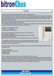
<strong>BASIC</strong> <strong>DIAGRAMS</strong> FOR 4+N WIRE ELECTRONIC DOOR PHONE <strong>SYSTEM</strong>S<br />
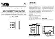
Connection of several door phones to 1 door unit<br />
Pressing one of the external panel buttons, the bitonal electronic<br />
call is sent to the correspondent door phone loudspeaker. When the<br />
called door phone handset is unhooked, contact is established and<br />
conversation may take place. To operate the electric lock it is suffi cient<br />
to press the proper push button.<br />
DEVICES<br />
The following devices are needed for the system illustrated in diagram<br />
SC101-1133C:<br />
DOOR PHONE REFERENCES<br />
N. X Door phones Mod. Atlantico White Ref. 1133<br />
or<br />
N. X Door phones Mod. Scaitel White Ref. 1132<br />
Black Ref. 1132/40<br />
or<br />
N. X Door phones Mod. Utopia Ref. 1134/1<br />
POWER SUPPLY FOR DOOR PHONE <strong>SYSTEM</strong> REFERENCES<br />
N. 1 Power supply for door phone system Ref. 786/11<br />
OUTDOOR STATION REFERENCES<br />
Sinthesi model<br />
N. Y Button modules Ref. 1145/11-/12-/13-/14<br />
N. 1 Module with door unit set-up Ref. 1145/20-/21-/22<br />
N. 1 Amplifi ed door unit Ref. 1145/500<br />
The panels must be installed in fl ush-mounting boxes with<br />
module holder frames or in cases with hood for wall-mounted<br />
versions. Refer to section “Panels Sinthesi” for respective<br />
diagrams and installation methods.<br />
4 −−−− sec.6 DOOR PHONE AND VIDEO DOOR PHONE <strong>SYSTEM</strong>: Product Technical Manual<br />
or<br />
K-Steel model<br />
N. Y Button modules Ref. 1155/11-/12A-/13A-/14A<br />
N. 1 Module with door unit Ref. 1155/20-/21-/22A<br />
or<br />
The panels must be installed in fl ush-mounting boxes with<br />
module holder frames or in cases with hood for wall-mounted<br />
versions. Refer to section “K-Steel modular vandal-proof panel”<br />
for respective diagrams and installation methods.<br />
725 model<br />
N. 1 Panel with N buttons Mod. 725<br />
N. 1 Amplifi ed door unit Ref. 5150/500<br />
or<br />
The panels must be installed in fl ush-mounting boxes with<br />
module holder frames or in cases with hood for wall-mounted<br />
versions. Refer to section “Panels with anodized Aluminium<br />
front plate Mod. 725” for respective diagrams and installation<br />
methods.<br />
Domus Aura model<br />
N. 1 Panel with N buttons Mod. 1110<br />
N. 1 Amplifi ed door unit Ref. 5150/500<br />
The panels must be installed in fl ush-mounting boxes with<br />
module holder frames or in cases with hood for wall-mounted<br />
versions. Refer to section “Panels Domus Aura” for respective<br />
diagrams and installation methods.<br />
DIAGRAM NOTES<br />
(see beginning section)<br />
C4.001 C4.004<br />
C4.006<br />
Sinthesi models only:<br />
Connect jumper L with G/T<br />
C4.007 C4.008
POWER SUPPLY<br />
FOR DOOR<br />
PHONE <strong>SYSTEM</strong><br />
<strong>BASIC</strong> <strong>DIAGRAMS</strong> FOR 4+N WIRE ELECTRONIC DOOR PHONE <strong>SYSTEM</strong>S<br />
Connection of several door phones to 1 door unit<br />
PS<br />
-J<br />
~0<br />
-6<br />
+6<br />
~<br />
~<br />
~12<br />
CA<br />
1<br />
2<br />
6<br />
9<br />
10<br />
CA<br />
1<br />
2<br />
6<br />
9<br />
10<br />
MAIN ~<br />
TO THE FOLLOWING<br />
DOOR PHONES<br />
(C4.004)<br />
(C4.006)<br />
Lock Release<br />
DOOR PHONE AND VIDEO DOOR PHONE <strong>SYSTEM</strong>: Product Technical Manual<br />
(C4.007)<br />
(C4.008)<br />
U4<br />
U3<br />
U2<br />
U1<br />
G/T<br />
~0<br />
~12<br />
~12<br />
~0<br />
G/T<br />
U2<br />
G/T<br />
U1<br />
~0<br />
G/T ~12<br />
~12<br />
~0<br />
L<br />
1A<br />
2<br />
-<br />
+<br />
1<br />
ELECTRIC LOCK<br />
TO THE FOLLOWING<br />
MODULE<br />
Name tag<br />
lighting<br />
SC101-1133C<br />
sec.6 −−−− 5<br />
<strong>BASIC</strong> <strong>SYSTEM</strong> <strong>DIAGRAMS</strong>
<strong>BASIC</strong> <strong>SYSTEM</strong> <strong>DIAGRAMS</strong><br />
FUNCTION<br />
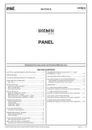
<strong>BASIC</strong> <strong>DIAGRAMS</strong> FOR 1+1 WIRE ELECTRONIC DOOR PHONE <strong>SYSTEM</strong>S<br />
Connection of door phones to 1 outdoor station with secrecy of conversation<br />
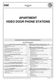
URMET DOMUS 1+1 wire system allows to obtain the service of a<br />
standard outdoor set installation with conversation, call, electric lock<br />
opening, with only 2 wires in the rising column: 1 common + 1 single<br />
for each door phone. The outdoor set is fed, with two wires only, by a<br />
12Vac voltage transformer.<br />
To assure call secrecy on all the door phones of the system, specifi c<br />
secrecy circuits (one for each button) are fi tted inside the push button<br />
panel. In this way, all the door phones are normally disabled for<br />
conversation (no conversation is heard when the hand-set is lifted);<br />
only the door phone called from the outside can start the conversation<br />
with the caller, certain that no other user can barge in and intercept the<br />
call.<br />
The door phone called remains enabled for conversation until a<br />
subsequent call to another appliance is made from the push button<br />
panel.<br />
Release of the electric lock is also enabled by the secrecy circuit<br />
which means that a user cannot open the lock unless he/she has been<br />
called.<br />
DEVICES<br />
The following devices are needed for the system illustrated in diagram<br />
SC101-1135F:<br />
DOOR PHONE REFERENCES<br />
N. X Door phones Mod. Atlantico Ref. 1133/35A<br />
or<br />
N. X Door phones Mod. Scaitel Ref. 1132/35<br />
or<br />
N. X Door phones Mod. Utopia Ref. 1134/35<br />
POWER SUPPLY FOR DOOR PHONE <strong>SYSTEM</strong> REFERENCES<br />
N. 1 Transformer Ref. 9000/230<br />
OUTDOOR STATION REFERENCES<br />
Sinthesi model<br />
N. X Button modules Ref. 1145/11-/12-/13-/14<br />
N. 1 Module with door unit set-up Ref. 1145/20-/21<br />
N. 1 Amplifi ed door unit Ref. 1145/67<br />
N. X/4 Conversation privacy device Ref. 1145/74<br />
The panels must be installed in fl ush-mounting boxes with<br />
module holder frames or in cases with hood for wall-mounted<br />
versions. Refer to section “Panels Sinthesi” for respective<br />
diagrams and installation methods.<br />
6 −−−− sec.6 DOOR PHONE AND VIDEO DOOR PHONE <strong>SYSTEM</strong>: Product Technical Manual<br />
or<br />
K-Steel model<br />
N. Y Button modules Ref. 1155/11-/12A-/13A-/14A<br />
N. 1 Module with door unit Ref. 1155/30-/31-/32A<br />
N. X/4 Conversation privacy device Ref. 1145/74<br />
The panels must be installed in fl ush-mounting boxes with<br />
module holder frames or in cases with hood for wall-mounted<br />
versions. Refer to section “K-Steel modular vandal-proof panel”<br />
for respective diagrams and installation methods.<br />
DIAGRAM NOTES<br />
(see beginning section)<br />
C1.002<br />
C4.006<br />
Sinthesi models only:<br />
Ponticellare C1 con U1<br />
C4.007<br />
C4.008<br />
VX.006<br />
VX.014
<strong>BASIC</strong> <strong>DIAGRAMS</strong> FOR 1+1 WIRE ELECTRONIC DOOR PHONE <strong>SYSTEM</strong>S<br />
Connection of door phones to 1 outdoor station with secrecy of conversation<br />
COLUMN<br />
DOOR PHONES<br />
~0<br />
~12<br />
~<br />
~<br />
~0<br />
~12<br />
~<br />
~<br />
CA1<br />
1<br />
2<br />
CA1<br />
1<br />
2<br />
TRANSFORMER<br />
LIGHT BULB<br />
TRANSFORMER<br />
MAIN ~<br />
(VX.014)<br />
MAIN ~<br />
CONVERSATION<br />
PRIVACY<br />
DEVICE<br />
(VX.006)<br />
1 4<br />
C4<br />
C3<br />
C2<br />
C1<br />
1 4<br />
DOOR PHONE AND VIDEO DOOR PHONE <strong>SYSTEM</strong>: Product Technical Manual<br />
(C4.006)<br />
Lock Release<br />
Name tag<br />
lighting<br />
TO THE FOLLOWING<br />
CONVERSATION<br />
PRIVACY<br />
DEVICE<br />
(C4.007)<br />
(C4.008)<br />
BUTTON MODULE<br />
U4<br />
U3<br />
U2<br />
U1<br />
U1<br />
C2<br />
C1<br />
PS<br />
4<br />
5<br />
F<br />
3<br />
SN<br />
1<br />
1/~<br />
~<br />
2<br />
TO THE FOLLOWING<br />
MODULE<br />
G/T<br />
~12<br />
~0<br />
~12<br />
G/T<br />
~0<br />
G/T<br />
G/T<br />
~0<br />
~12<br />
~12<br />
~0<br />
DOOR UNIT<br />
Name tag<br />
lighting<br />
ELECTRIC LOCK<br />
SC101-1135F<br />
sec.6 −−−− 7<br />
<strong>BASIC</strong> <strong>SYSTEM</strong> <strong>DIAGRAMS</strong>
<strong>BASIC</strong> <strong>SYSTEM</strong> <strong>DIAGRAMS</strong><br />
FUNCTION<br />
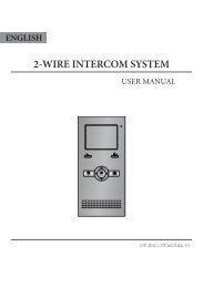
<strong>BASIC</strong> <strong>DIAGRAMS</strong> FOR COAX ELECTRONIC VIDEO DOOR PHONE <strong>SYSTEM</strong>S<br />
Connection of video door phones to 1 video outdoor station<br />
This system allows connection between the video outdoor station<br />
and the various monitors situated in the apartments. When the visitor<br />
presses a button on the push button panel, the bitonal electronic call<br />
is sent to the corresponding monitor loudspeaker and, after about 8<br />
seconds, the image appears on the screen.<br />
At this point the user sees the visitor and can answer, if he wishes,<br />
unhooking the handset.<br />
At the end of the conversation, the electric lock can be operated by<br />
pressing the key ( ).<br />
Vision of the image lasts about 60 seconds, after which the intervention<br />
of the built-in timer in the power supply causes it to go off. If a second<br />
monitor is called before the end of the 60 seconds, the fi rst monitor will<br />
automatically go off and the latter comes on. This feature guarantees<br />
secrecy of vision.<br />
DIAGRAM NOTES<br />
7+coax<br />
7+coax<br />
(see beginning section)<br />
C4.006<br />
Sinthesi models only:<br />
Connect jumper L with G/T<br />
C4.007 C4.008<br />
VD.002<br />
VX.003 VX.008<br />
VX.010 VX.011 VX.014<br />
6+(n-2)+coax<br />
6+(n-1)+coax<br />
6+n+coax<br />
9+n+coax<br />
TC<br />
DEVICES<br />
The following devices are needed for the system illustrated in diagram<br />
SV102-2631E:<br />
VIDEO DOOR PHONE REFERENCES<br />
Atlantico model<br />
N. X Video door phone Ref. 1702/1<br />
N. X Bracket Ref.1202/90<br />
8 −−−− sec.6 DOOR PHONE AND VIDEO DOOR PHONE <strong>SYSTEM</strong>: Product Technical Manual<br />
or<br />
Artico model<br />
N. X Video door phone Ref. 1705/1<br />
N. X Bracket Ref. 1705/90<br />
VIDEO OUTDOOR STATION <strong>DIAGRAMS</strong><br />
Sinthesi model<br />
N. 1 Camera modules with built-in door unit Ref. 1745/80-/81-/82<br />
N. X Button modules Ref. 1145/11-/12-/13-/14<br />
or<br />
The panels must be installed in fl ush-mounting boxes with<br />
module holder frames or in cases with hood for wall-mounted<br />
versions. Refer to section “Panels Sinthesi” for respective<br />
diagrams and installation methods.<br />
K-Steel model<br />
N. 1 Camera modules with built-in door unit Ref. 1755/80<br />
N. X Button modules Ref. 1155/11-/12A-/13A-/14A<br />
or<br />
The panels must be installed in fl ush-mounting boxes with<br />
module holder frames or in cases with hood for wall-mounted<br />
versions. Refer to section “K-Steel modular vandal-proof panel”<br />
for respective diagrams and installation methods.<br />
725 model<br />
N. 1 Panel with N buttons Mod. 725<br />
N. 1 Amplifi ed door unit Ref. 5150/500<br />
N. 1 Camera Ref. 725/600<br />
N. 1 Front plate Ref. 725/601-/602<br />
or<br />
The panels must be installed in fl ush-mounting boxes with<br />
module holder frames or in cases with hood for wall-mounted<br />
versions. Refer to section “Panels with anodized Aluminium<br />
front plate Mod. 725” for respective diagrams and installation<br />
methods.<br />
Domus Aura model<br />
N. 1 Panel with N buttons Mod. 1110<br />
N. 1 Amplifi ed door unit Ref. 5150/500<br />
N. 1 Camera Ref. 1810/70<br />
The panels must be installed in fl ush-mounting boxes with<br />
module holder frames or in cases with hood for wall-mounted<br />
versions. Refer to section “Panels Domus Aura” for respective<br />
diagrams and installation methods.<br />
POWER SUPPLY<br />
N. 1 Video power supply Ref. 789/5B<br />
N. 1 Video distributor Ref. 1794/4A<br />
N. 1 Transformer Ref. 9000/230<br />
TC
VIDEO<br />
POWER SUPPLY<br />
(VX.008)<br />
<strong>BASIC</strong> <strong>DIAGRAMS</strong> FOR COAX ELECTRONIC VIDEO DOOR PHONE <strong>SYSTEM</strong>S<br />
Connection of video door phones to 1 video outdoor station<br />
(VX.010)<br />
(VX.011)<br />
R1<br />
R2<br />
V4<br />
V5<br />
V3<br />
R1<br />
R2<br />
V4<br />
V5<br />
V3<br />
U1<br />
U2<br />
R2<br />
R1<br />
E<br />
PS<br />
~12<br />
SE1<br />
AP<br />
~0<br />
-6<br />
+6<br />
+TC<br />
R1<br />
R1<br />
R2<br />
SE2<br />
~<br />
~<br />
(C4.006)<br />
DOOR PHONE AND VIDEO DOOR PHONE <strong>SYSTEM</strong>: Product Technical Manual<br />
CA<br />
1<br />
2<br />
6<br />
9<br />
10<br />
X1<br />
X2<br />
Y1<br />
Y2<br />
R3<br />
CA<br />
1<br />
2<br />
6<br />
9<br />
10<br />
X1<br />
X2<br />
Y1<br />
Y2<br />
R3<br />
VIDEO<br />
DISTRIBUTOR<br />
LINE ~<br />
Lock Release<br />
(C4.007)<br />
(C4.008)<br />
U4<br />
U3<br />
U2<br />
U1<br />
U4<br />
U3<br />
U2<br />
U1<br />
G/T<br />
L<br />
1A<br />
2<br />
-<br />
+<br />
1<br />
V5<br />
V3<br />
+TC<br />
R1<br />
TRANSFORMER<br />
G/T<br />
~12<br />
~0<br />
~0<br />
~12<br />
G/T<br />
G/T<br />
~12<br />
~0<br />
~0<br />
~12<br />
~12<br />
~0<br />
ELECTRIC LOCK<br />
TO THE FOLLOWING<br />
MODULE<br />
~0<br />
~12<br />
~<br />
~<br />
SV102-2631E<br />
Name tag<br />
lighting<br />
(VD.002)<br />
Name tag<br />
lighting<br />
(VX.014)<br />
TC<br />
LINE~<br />
sec.6 −−−− 9<br />
<strong>BASIC</strong> <strong>SYSTEM</strong> <strong>DIAGRAMS</strong>
<strong>BASIC</strong> <strong>SYSTEM</strong> <strong>DIAGRAMS</strong><br />
FUNCTION<br />
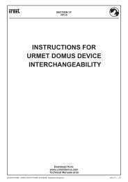
The 5-wire video door phone system implements conversation privacy,<br />
call and door opener functions in normal door phone systems with only<br />
5 wires in the riser column: 4 common + 1 single for each device.<br />
The door unit is powered with only two wires and a transformer at<br />
12V~.<br />
The most interesting application of a 5-wire system is in old building<br />
where a door phone system is already fi tted. The existing service can<br />
be transformed into a video door phone system without adding wires<br />
to the column or in the apartments.<br />
Specifi c conversation privacy circuits must be fi tted in the panel for<br />
ensuring conversation privacy for all video door phones in the system<br />
(one for each button).<br />
All video door phones are normally deactivated (no sound is heard<br />
when the handset is picked up); only the video door phone called from<br />
the door can start the conversation. No other users can cut into the<br />
call.<br />
The voice circuit of the called video door phone remains activate until<br />
the following call is made from the panel to another device.<br />
The door opening function is connected to conversation privacy; this<br />
means that a user must be called to be able to open the electrical<br />
lock.<br />
DEVICES<br />
The following devices are needed for the system illustrated in diagram<br />
SV102-2633H:<br />
VIDEO DOOR PHONE REFERENCES<br />
Atlantico model (A)<br />
N. X Video door phone Ref. 1702/1<br />
N. X Bracket Ref. 1202/955<br />
or<br />
Artico model (A)<br />
N. X Video door phone Ref. 1705/1<br />
N. X Bracket Ref. 1705/955<br />
or<br />
TC<br />
<strong>BASIC</strong> <strong>DIAGRAMS</strong> FOR 5-WIRE ELECTRONIC DOOR PHONE <strong>SYSTEM</strong>S<br />
Connection of a video door phone riser to a video outdoor station<br />
with secrecy device<br />
CONNECT 2 82Ohm<br />
RESISTORS-1/4W<br />
VIDEO<br />
DISTRIBUTOR<br />
VIDEO<br />
DISTRIBUTOR<br />
Scaitel model (B)<br />
N. X Video module Ref. 1732/1<br />
N. X Bracket Ref. 1732/955<br />
N. X Door phone Ref. 1132/35<br />
VIDEO OUTDOOR STATION <strong>DIAGRAMS</strong><br />
Sinthesi model<br />
N. X Button modules Ref. 1145/11-/12-/13-/14<br />
N. 1 Camera modules with built in door unit Ref. 1745/20-/21-/22<br />
N. X Conversation privacy device Ref. 1145/74<br />
The panels must be installed in fl ush-mounting boxes with<br />
module holder frames or in cases with hood for wall-mounted<br />
versions. Refer to section “Panels Sinthesi” for respective<br />
diagrams and installation methods.<br />
10 −−−− sec.6 DOOR PHONE AND VIDEO DOOR PHONE <strong>SYSTEM</strong>: Product Technical Manual<br />
or<br />
K-Steel model<br />
N. X Button modules Ref. 1155/11-/12A-/13A-/14A<br />
N. 1 Camera modules Ref. 1755/30<br />
N. 1 Door unit module Ref. 1155/30-/31-/32A<br />
N. X Conversation privacy device Ref. 1145/74<br />
or<br />
The panels must be installed in fl ush-mounting boxes with<br />
module holder frames or in cases with hood for wall-mounted<br />
versions. Refer to section “K-Steel modular vandal-proof panel”<br />
for respective diagrams and installation methods.<br />
725 model<br />
N. 1 Panel with N buttons (min. 4) Mod. 725<br />
N. 1 Amplifi ed door unit Ref. 1035/67<br />
N. 1 Camera Ref. 725/600<br />
N. 1 Video adapter Ref. 1742/13A<br />
N. 1 Frontal plate Ref. 725/601 or /602<br />
N. X Conversation privacy device Ref. 1035/25<br />
or<br />
The panels must be installed in fl ush-mounting boxes with<br />
module holder frames or in cases with hood for wall-mounted<br />
versions. Refer to section “Panels with anodized Aluminium<br />
front plate Mod. 725” for respective diagrams and installation<br />
methods.<br />
Domus Aura model<br />
N. 1 Panel with N buttons (min. 3) Mod. 1710<br />
N. 1 Amplifi ed door unit Ref. 1035/67<br />
N. 1 Camera Ref. 1810/70<br />
N. 1 Video adapter Ref. 1742/13A<br />
N. X Conversation privacy device Ref. 1110/74<br />
The panels must be installed in fl ush-mounting boxes with<br />
module holder frames or in cases with hood for wall-mounted<br />
versions. Refer to section “Panels Domus Aura” for respective<br />
diagrams and installation methods.<br />
MISCELLANEOUS<br />
N. 1 Video power supply Ref. 789/5B<br />
N. X Video distributor Ref. 955/40<br />
DIAGRAM NOTES<br />
(see beginning section)<br />
C4.007 C4.008 C4.018 V5.001 VD.002<br />
VX.006 VX.008 VX.014<br />
VX.018<br />
Connect the following jumpers on the device:<br />
a) R1 to 1 b) CA to 2<br />
TC
Name tag<br />
lighting<br />
TC<br />
(CU.009)<br />
P. E.<br />
PS 4<br />
3<br />
SN<br />
1/~<br />
2<br />
5<br />
~<br />
TV-camera A<br />
B<br />
+ R1<br />
Adapter<br />
+TC<br />
Mod.725/Domus-Aura<br />
<strong>BASIC</strong> <strong>DIAGRAMS</strong> FOR 5-WIRE ELECTRONIC DOOR PHONE <strong>SYSTEM</strong>S<br />
Connection of a video door phone riser to a video outdoor station<br />
with secrecy device<br />
4 1 1 4<br />
(VU.002)<br />
ELECTRIC LOCK<br />
Mod. K-Steel/Sinthesi<br />
DOOR PHONE AND VIDEO DOOR PHONE <strong>SYSTEM</strong>: Product Technical Manual<br />
"A"<br />
"A"<br />
"A"<br />
"A"<br />
TO THE FOLLOWING<br />
MODULE<br />
(VD.002)<br />
R1 BA<br />
+TC<br />
~12<br />
~0<br />
R1 BA<br />
+TC<br />
K-Steel Sinthesi<br />
R1<br />
R2<br />
A<br />
B<br />
CA<br />
R1<br />
R2<br />
A<br />
B<br />
CA<br />
R1<br />
R2<br />
A<br />
B<br />
CA<br />
R1<br />
R2<br />
A<br />
B<br />
CA<br />
TO THE FOLLOWING<br />
CONVERSATION<br />
PRIVACY DEVICE<br />
TO THE FOLLOWING<br />
VIDEO DISTRIBUTOR<br />
(C4.007)<br />
(C4.008)<br />
G/T<br />
4 1<br />
(VX.006)<br />
~12<br />
~0<br />
~0<br />
~12<br />
G/T<br />
U4<br />
U3<br />
U2<br />
U1<br />
C4<br />
C3<br />
C2<br />
C1<br />
4 1 (VX.006)<br />
C2<br />
C1<br />
C2<br />
C1<br />
C4.018)<br />
~12<br />
~0<br />
PS<br />
G/T<br />
F<br />
5<br />
4<br />
SN<br />
1<br />
1/~<br />
~<br />
2<br />
PS<br />
G/T<br />
F<br />
5<br />
4<br />
SN<br />
1/~<br />
1/~<br />
~<br />
SE<br />
3<br />
BUTTON MODULE<br />
Name tag<br />
lighting<br />
To The<br />
Following<br />
Privacy<br />
Device<br />
Lock<br />
Release<br />
ELECTRIC LOCK<br />
Lock Release<br />
R1<br />
R2<br />
A<br />
B<br />
R1<br />
R2<br />
A<br />
B<br />
R1<br />
R2<br />
A<br />
B<br />
R1<br />
R2<br />
A<br />
B<br />
Name tag<br />
lighting<br />
A B<br />
Output<br />
R1<br />
R2<br />
III II<br />
A<br />
B<br />
IV<br />
A B<br />
R2R1<br />
VIDEO<br />
DISTRIBUTOR<br />
Ref.955/40<br />
A B<br />
I<br />
R2R1<br />
R1<br />
R2<br />
A<br />
B<br />
Output<br />
R1<br />
R2<br />
III II<br />
A<br />
B<br />
IV<br />
A B<br />
Input<br />
R2R1<br />
VIDEO<br />
DISTRIBUTOR<br />
Ref.955/40<br />
LINE ~<br />
Input<br />
I<br />
R2R1<br />
2 x 82Ω1/4W<br />
R1<br />
R2<br />
A<br />
B<br />
LINE ~<br />
(VX.014)<br />
VIDEO MODULE<br />
R1<br />
R1<br />
R2<br />
R2<br />
A<br />
B<br />
CA<br />
VIDEO MODULE<br />
R1<br />
R1<br />
R2<br />
R2<br />
A<br />
B<br />
CA<br />
+6<br />
-6<br />
AP<br />
R1<br />
R2<br />
+R<br />
PS<br />
1/~<br />
~0<br />
~12<br />
SE2<br />
SE1<br />
R2<br />
R1<br />
+TC<br />
~<br />
~<br />
~0<br />
~12<br />
~<br />
~<br />
VIDEO DOOR PHONES<br />
R1<br />
R2<br />
A<br />
B<br />
CA<br />
(VX.018)<br />
R1<br />
R2<br />
A<br />
B<br />
CA<br />
(VX.018)<br />
VIDEO<br />
POWER SUPPLY<br />
Ref.789/5B<br />
(VX.008)<br />
SV102-2633H<br />
DOOR PHONE<br />
1<br />
CA1<br />
2<br />
VIDEO DOOR PHONES<br />
DOOR PHONE<br />
1<br />
CA1<br />
2<br />
TRANSFORMER<br />
"A"<br />
"B"<br />
"A"<br />
"B"<br />
sec.6 −−−− 11<br />
<strong>BASIC</strong> <strong>SYSTEM</strong> <strong>DIAGRAMS</strong>
SECTION 6 CONTENTS<br />
DOOR PHONE AND VIDEO DOOR PHONE <strong>SYSTEM</strong> - PRODUCT TECHNICAL MANUAL<br />
<strong>BASIC</strong> <strong>SYSTEM</strong> <strong>DIAGRAMS</strong><br />
DOOR PHONE AND VIDEO DOOR PHONE <strong>SYSTEM</strong>: Product Technical Manual<br />
Diagrams Section Pag.<br />
DIAGRAM NOTES .................................................................................................................................................................................6 ................2<br />
<strong>BASIC</strong> <strong>DIAGRAMS</strong> FOR 4+N WIRE ELECTRONIC DOOR PHONE <strong>SYSTEM</strong>S<br />
Connection of several door phones to 1 door unit.........................................................................................SC101-1133C .................6 ................4<br />
<strong>BASIC</strong> <strong>DIAGRAMS</strong> FOR 1+1 WIRE ELECTRONIC DOOR PHONE <strong>SYSTEM</strong>S<br />
Connection of door phones to 1 outdoor station with secrecy of conversation ............................................. SC101-1135F .................6 ................6<br />
<strong>BASIC</strong> <strong>DIAGRAMS</strong> FOR COAX ELECTRONIC VIDEO DOOR PHONE <strong>SYSTEM</strong>S<br />
Connection of video door phones to 1 video outdoor station ........................................................................ SV102-2631E .................6 ................8<br />
<strong>BASIC</strong> <strong>DIAGRAMS</strong> FOR 5-WIRE ELECTRONIC DOOR PHONE <strong>SYSTEM</strong>S<br />
Connection of a video door phone riser to a video outdoor station with secrecy device............................... SV102-2633H .................6 ............. 10<br />
sec.6 −−−− II<br />
DOOR PHONE AND VIDEO DOOR PHONE <strong>SYSTEM</strong> - PRODUCT TECHNICAL MANUAL - Section 6