RESEARCH CONTROL Valves Selection Guide - Badger Meter, Inc.
RESEARCH CONTROL Valves Selection Guide - Badger Meter, Inc.
RESEARCH CONTROL Valves Selection Guide - Badger Meter, Inc.

Create successful ePaper yourself
Turn your PDF publications into a flip-book with our unique Google optimized e-Paper software.
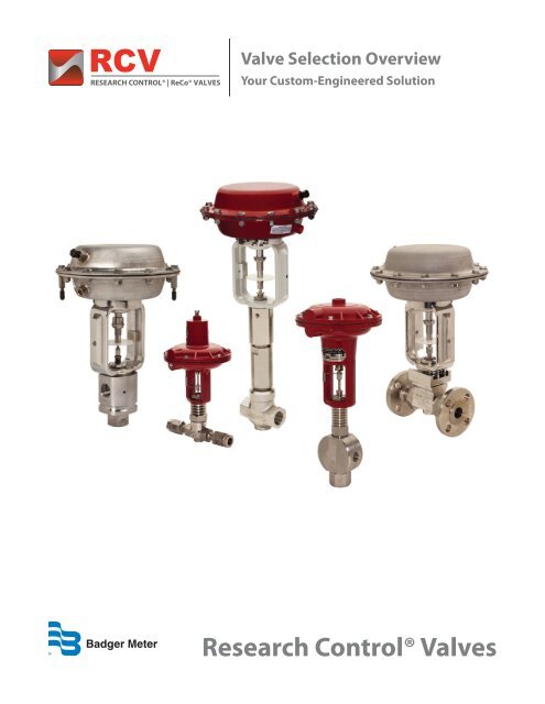
Valve <strong>Selection</strong> Overview<br />
Your Custom-Engineered Solution<br />
Research Control® <strong>Valves</strong>
2 Valve <strong>Selection</strong> Overview
Your Custom-Engineered Valve Solution<br />
Step-By-Step<br />
Feature-rich <strong>Badger</strong> <strong>Meter</strong> Research Control <strong>Valves</strong> are custom-designed to match your stringent<br />
parameters. To help ensure the right fit, we offer an extensive range of options – from unique valve alloys<br />
to custom-fit accessories. These selections can be combined in millions of ways to create a distinctive<br />
solution. This selection guide is designed to help you explore the possibilities between our combinations<br />
and your applications.<br />
Start by taking a look at our portfolio – At-A-Glance. Then, review your options, step-by-step:<br />
Step 1: Valve Alloys<br />
Step 2: End Connections<br />
Step 3: Bonnet <strong>Selection</strong>s<br />
Step 4: Guiding Options<br />
Step 5: Operating Temperature and Pressure Parameters<br />
Step 6: Packing Choices<br />
Step 7: Innervalve Trim Set Solutions<br />
Step 8: Custom-Fit Accessories<br />
Step 9: Product Definition, Pricing and Delivery<br />
Your Custom-Engineered Valve Solution 3
Valve <strong>Selection</strong> At-A-Glance<br />
General Industrial and Research Applications<br />
Your custom-engineered solution will be based on our product portfolio. Review our offerings here to help<br />
determine which type of valve will meet your requirements. Each valve can be made with most flange<br />
types and sizes, welded connections, NPT, or tube fittings.<br />
Pictured below are selections for general industrial and research applications. The next page includes the<br />
process control and sanitary offerings.<br />
Small Control <strong>Valves</strong><br />
Standard Flange<br />
Standard Globe<br />
3-Way and<br />
Diverting<br />
Manual<br />
Bellows<br />
Exotic Alloys<br />
Kynar<br />
Cryogenic and High Temperature <strong>Valves</strong><br />
Standard<br />
Fin<br />
Extended<br />
Fin<br />
14" Extended<br />
Bonnet<br />
Cold Box<br />
Extension<br />
4<br />
Valve <strong>Selection</strong> At-A-Glance
Valve <strong>Selection</strong> At-A-Glance<br />
Process Control and Sanitary Applications<br />
Listed below are selections for process control and sanitary applications.<br />
High Pressure and Severe Service <strong>Valves</strong><br />
60,000 psi<br />
40,000 psi<br />
10,000 psi<br />
Severe Service<br />
Process Control <strong>Valves</strong><br />
9000<br />
9000 Flange<br />
9000 Extended<br />
Bonnet<br />
9000 3-Way and<br />
Diverting<br />
9100 9100 Extension<br />
Sanitary Control <strong>Valves</strong><br />
SCV 85<br />
Barstock<br />
SCV 89<br />
Investment Cast<br />
SCV 95<br />
Investment Cast<br />
Valve <strong>Selection</strong> At-A-Glance 5
Step 1<br />
Valve Alloys<br />
Research Control Valve bodies and trims are manufactured from common products like 316 SS or Monel®<br />
to more exotic alloys like tantalum. Trims are normally supplied in the same material as the body, except<br />
where conditions require the use of other materials. Our technicians can help identify valve alloys that will<br />
complement your operation.<br />
Options include:<br />
Body Alloys<br />
• 316/316L stainless steel*<br />
• 304/304L stainless steel*<br />
• 347 stainless steel<br />
• Brass<br />
• Bronze*<br />
• Carbon steel*<br />
• Monel* e<br />
• Alloy 20* e<br />
• Alloy B* e<br />
• Alloy C* e<br />
• Alloy G e<br />
• <strong>Inc</strong>onel®* e<br />
• Titanium e<br />
• Tantalum e<br />
• Nickel e<br />
• Kynar®* e<br />
• Zirconium e<br />
• DIN 1.4581 e<br />
• DIN 1.4571<br />
• DIN 1.4539<br />
• DIN 1.4404 e<br />
• DIN 2.4819 e<br />
• DIN 2.4617 e<br />
• Aluminum e<br />
• Duplex stainless* e<br />
• Haynes® HR-120 e<br />
Trim Alloys<br />
• 316/316L stainless steel*<br />
• 304/304L stainless steel*<br />
• 347 stainless steel<br />
• 316/Kel-F*<br />
• 316/Teflon®*<br />
• 316/Stellite®*<br />
• Monel*<br />
• Alloy 20*<br />
• Alloy B*<br />
• Alloy C*<br />
• Hastelloy® C22*<br />
• <strong>Inc</strong>onel*<br />
• Titanium<br />
• Tantalum<br />
• Nickel<br />
• Kynar*<br />
• Zirconium<br />
• Duplex stainless*<br />
• Stellite/304*<br />
• Stellite/316*<br />
• Stellite/416*<br />
• Stellite/Alloy 20*<br />
• Stellite/Alloy bronze*<br />
• Stellite/Alloy B*<br />
• Stellite/Alloy C*<br />
• Stellite/Monel*<br />
6<br />
Valve Alloys<br />
* Stocked for orders.<br />
e<br />
Alloy export control.
Step 2<br />
End Connections<br />
End connections are dependent on a variety of factors such as pressure, temperature, size, or the frequency<br />
of removing the valve from the line. Our control valve end connections have single point threads to prevent<br />
galling and stripping.<br />
<strong>Selection</strong>s include:<br />
Autoclave Body BSP-P (G) Butt Weld Body Flanged Body NPT Body<br />
Socket Weld Body Swagelok Body Triclamp Body VCR and VCO Body Wafer Body<br />
Step 3<br />
Bonnet <strong>Selection</strong>s<br />
Bonnet selection is a key element in specifying the correct control valve. <strong>Badger</strong> <strong>Meter</strong> offers a<br />
comprehensive selection of Research Control Valve bonnets to meet a wide range of requirements. Review<br />
the chart below. If your application is out of this range, please contact us. Depending on your specific<br />
requirements, we may be able to design a solution that can meet your needs.<br />
Packing Temperature<br />
Bonnet Length <strong>Selection</strong><br />
Standard Bonnet Standard Fin Extended Fin<br />
350° F (177° C)<br />
300° F (149° C)<br />
250° F (121° C)<br />
350° F (93° C)<br />
150° F (66° C)<br />
100° F (36° C)<br />
100° F 200° F 300° F 400° F 500° F 600° F 700° F 800° F 900° F 1000° F<br />
38° C 93° C 149° C 204° C 260° C 316° C 371° C 427° C 482° C 593° C<br />
Process Temperature<br />
End Connections | Bonnet <strong>Selection</strong>s<br />
7
Step 4<br />
Guiding Options<br />
<strong>Badger</strong> <strong>Meter</strong> also provides a range of guiding options, including:<br />
• Top <strong>Guide</strong>d - A top guided innervalve is stem-guided at the packing. Some innervalves could be<br />
considered “seat-guided,” due to the inherent close fit between the plug and seat.<br />
• Medium <strong>Guide</strong>d - A medium guided trim is guided at the packing and in the bonnet. The medium<br />
guided style was developed to provide a guide option for those wishing to use standard bonnets rather<br />
than heavy-duty versions. Medium guided trims, when available, will fit standard bonnets.<br />
• Heavy-Duty <strong>Guide</strong>d - The heavy-duty guided trim provides maximum resistance to actuator force and<br />
pressure induced vibration. The bonnet and trim will not interchange with the standard bonnet designs.<br />
Step 5<br />
Operating Temperature and Pressure Range Parameters<br />
Temperature and pressure parameters are key considerations in bonnet, guiding and packing selection.<br />
Research Control <strong>Valves</strong> can meet pressure parameters from full vacuum to 60,000 psi. Operating<br />
temperatures range from extreme cold (-450° F) to extreme heat (1500° F).<br />
60,000 psi<br />
High Pressure<br />
10,000 psi<br />
Severe Service<br />
5,000 psi<br />
Pressure<br />
Small and Process Control Valve<br />
Atmosphere<br />
Cryogenics<br />
Sanitary<br />
High Temperature<br />
Kynar<br />
Full Vacuum<br />
Temperature<br />
-450° F Ambient 500° F 1000° F 1500° F<br />
8<br />
Guiding Options | Operating Temperature and Pressure Range Parameters
Step 6<br />
Packing Choices<br />
With today’s demanding applications and expanded regulations, leakage is not an option. Our packing<br />
choices are extensive – and reflect current industry needs. In addition to pressure and temperature<br />
parameters, there are many other factors to consider when customizing your packing configuration,<br />
including hysteresis, seal quality, maintenance and cycle life. If you have any questions regarding your<br />
application and its demands, contact us. We will help you select the correct solution.<br />
Fugitive Emissions Control<br />
Packing (REK) -<br />
0 ppm at 150 psi (leakage based on<br />
EPA Method 21)<br />
Single or Double PTFE Chevron<br />
Packing<br />
Bellows packing<br />
Grafoil® Packing<br />
Spring-Loaded Packing – Triple<br />
PTFE Chevron Packing<br />
Customized Packing Solutions<br />
• Proven choice for critical applications where leakage is not an option<br />
• Twelve varieties of REK elastomer combinations are available<br />
including Kalrez, Zymaxx, Virgin PTFE, Moly/Glass filled PTFE and PFA,<br />
which provides a wide range of sealability<br />
• Standard packing for Research Control <strong>Valves</strong><br />
• Provides low friction and high chemical compatibility<br />
• Provides a flexible, static seal, commonly used in critical situations:<br />
› High Pressure (1500 psi), Low Pressure (580 psi), and<br />
Various Alloys (Alloy C, Monel and <strong>Inc</strong>onel)<br />
• One of many high temperature options<br />
• Combines Chevron packing and a stainless steel spring to provide a<br />
consistent live load<br />
• Designed to meet your needs<br />
• Based on our experience with countless critical applications<br />
throughout the past 65 years<br />
Port Options<br />
Your Research Control <strong>Valves</strong> packing solution also includes leak detection and purge port options.<br />
Single Packing Double Packing Double Packing with Purge Port<br />
1<br />
2<br />
3<br />
1<br />
2<br />
3<br />
1<br />
2<br />
3<br />
1<br />
2<br />
3<br />
1<br />
2<br />
3<br />
1<br />
2<br />
3<br />
1<br />
2<br />
3<br />
1<br />
2<br />
3<br />
1<br />
2<br />
3<br />
4<br />
4<br />
4<br />
5<br />
6<br />
5<br />
5<br />
6<br />
6<br />
4 4<br />
4<br />
4 4<br />
4<br />
1. Packing Gland 2. Packing Follower 3. Packing CV Ring 4. Packing Adapter 5. Seperator Ring 6. Lanem Ring<br />
Packing Choices<br />
9
10<br />
Step 7<br />
90<br />
Innervalve Trim Set Solutions<br />
80<br />
Flow Characteristics<br />
10<br />
The innervalve represents the “heart” of 30 the control valve and includes a single seat, profiled plug and a<br />
0 2010 20 30 40 50 60 70 80 90 100<br />
range of trim selections. Research Control 10 Valve trim configurations are engineered for precise small and<br />
0<br />
medium flow control (Cv from 0.0000018 0to 10 54) 20 and 30 40are 50 designed 60 70 80 90 to 100 match the flow profiles of your system.<br />
Selecting the appropriate flow characteristics 90 and trim size will enable your system to function within its<br />
100<br />
design specifications. Trim configurations 70 are available to match the flow characteristics below. Trim sizing<br />
80<br />
guidelines are available on the following 50 pages.<br />
Trim Flow Characteristics <strong>Inc</strong>lude:<br />
Equal Percentage<br />
Percent Percent of Maximum of Maximum Flow Flow<br />
100<br />
90<br />
100 80<br />
70 90<br />
60 80<br />
50 70<br />
40 60<br />
30 50<br />
20 40<br />
10 30<br />
20 0<br />
10 0 10 20 30 40 50 60 70 80 90 100<br />
0<br />
Percent of Lift<br />
0 10 20 30 40 50 60 70 80 90 100<br />
Percent of Lift<br />
100<br />
Linear<br />
90<br />
Percent Percent of Maximum of Maximum Flow Flow<br />
Percent Percent of Maximum of Maximum Flow Flow<br />
100 80<br />
70 90<br />
60 80<br />
50 70<br />
40 60<br />
30 50<br />
20 40<br />
10 30<br />
20 0<br />
10 0 10 20 30 40 50 60 70 80 90 100<br />
0<br />
Percent of Lift<br />
0 10 20 30 40 50 60 70 80 90 100<br />
Percent of Lift<br />
100<br />
90<br />
100 80<br />
70 90<br />
Sizing 60 80<br />
<strong>Guide</strong>lines<br />
50 70<br />
40 60<br />
30 50<br />
90<br />
70<br />
80 Innervalve Trim Set Solutions<br />
Soft Seat Trim Option:<br />
Trim configurations also include<br />
soft seat trim options:<br />
• Replaceable<br />
• PTFE and Kel-F<br />
• Available with all flow<br />
characteristics<br />
• Available with all listed<br />
alloys<br />
Use 20 40 the chart on the next page to help identify the best possible Research Control Valve trim size for your<br />
10<br />
application 20 0 and flow characteristics. For additional detail regarding rangeability, see the chart on page 14.<br />
10 0 10 20 30 40 50 60 70 80 90 100<br />
0<br />
Percent of Lift<br />
Note: Trims are Percent interchangeable of Lift<br />
with valves of like configuration.<br />
t Percent of Maximum of Maximum Flow Flow<br />
30<br />
100<br />
90<br />
100<br />
80<br />
60<br />
70<br />
50<br />
60<br />
40<br />
50<br />
30<br />
40<br />
20<br />
0 10 20 30 40 50 60 70 80 90 100<br />
Percent of Maximum Flow<br />
Percent of Maximum Flow<br />
Percent of Maximum Flow<br />
100<br />
70<br />
60<br />
50<br />
40<br />
30<br />
20<br />
0<br />
100<br />
80<br />
60<br />
Percent of Lift<br />
70<br />
40<br />
60<br />
30<br />
50<br />
20<br />
40<br />
10<br />
30<br />
0<br />
20<br />
0 10 20 30 40 50 60 70 80 90 100<br />
10<br />
Percent of Lift<br />
0<br />
100<br />
90<br />
80<br />
70<br />
60<br />
50<br />
40<br />
30<br />
20<br />
10<br />
0<br />
10<br />
0 10 10 20 30 40 50 60 70 80 90 100<br />
0<br />
Percent of Lift<br />
0 10 20 30 40 50 60 70 80 90 100<br />
Percent of Lift<br />
Double 100 Taper<br />
90<br />
100<br />
80<br />
90<br />
70<br />
80<br />
60<br />
70<br />
50<br />
60<br />
40<br />
50<br />
30<br />
40<br />
20<br />
30<br />
Percent of Maximum Flow<br />
Percent of Maximum Flow<br />
Percent of Maximum Flow<br />
Percent of Maximum Flow<br />
100<br />
90<br />
80<br />
70<br />
60<br />
50<br />
40<br />
90<br />
Quick Opening<br />
Percent of Maximum Flow<br />
Percent of Lift<br />
0 10 20 30 40 50 60 70 80 90 100<br />
Percent of Lift<br />
100<br />
90<br />
80<br />
70<br />
60<br />
50<br />
40<br />
30<br />
20<br />
20<br />
0<br />
10<br />
0 10 20 30 40 50 60 70 80 90 100<br />
0<br />
0 10 20 30 Percent 40 of Lift 50 60 70 80 90 100<br />
Percent of Lift
Innervalve Chart: Research Control <strong>Valves</strong><br />
Trim Size<br />
Max Cv<br />
Max Kv<br />
Rangeability<br />
Linear<br />
Rangeability<br />
Equal %<br />
Orifice<br />
Port Area<br />
In 2<br />
Flow<br />
Characteristics<br />
1/4"<br />
P18 0.0000018 0.000001548 15:1 NA 0.042 0.0014 L, DT<br />
P17 0.0000027 0.000002322 15:1 NA 0.042 0.0014 L, DT<br />
P16 0.000004 0.00000344 15:1 NA 0.042 0.0014 L, DT<br />
P15 0.000006 0.00000516 15:1 NA 0.042 0.0014 L, DT<br />
P14 0.00001 0.0000086 15:1 NA 0.042 0.0014 L, DT<br />
P13 0.000016 0.00001376 15:1 NA 0.042 0.0014 L, DT<br />
P12 0.000024 0.00002064 15:1 NA 0.042 0.0014 L, DT<br />
P11 0.000036 0.00003096 15:1 NA 0.042 0.0014 L, DT<br />
P10 0.00005 0.000043 15:1 NA 0.042 0.0014 L, DT<br />
1/4" & 1/2" P9 0.00008 0.0000688 15:1 NA 0.0625 0.0031 L, DT<br />
P8 0.00012 0.0001032 15:1 NA 0.0625 0.0031 L, DT<br />
P7 0.00018 0.0001548 15:1 NA 0.0625 0.0031 L, DT<br />
P6 0.00027 0.0002322 15:1 NA 0.0625 0.0031 L, DT<br />
P5 0.0004 0.000344 15:1 NA 0.0625 0.0031 L, DT<br />
P4 0.0006 0.000516 15:1 NA 0.0625 0.0031 L, DT<br />
P3 0.001 0.00086 15:1 NA 0.0625 0.0031 L, DT<br />
P2 0.0013 0.001118 15:1 NA 0.0625 0.0031 L, DT<br />
P1 0.002 0.00172 15:1 NA 0.0625 0.0031 L, DT<br />
1/4", 1/2", 3/4" & 1" O 0.003 0.00258 25:1 NA 0.086 0.0058 FT, L, QO, DT<br />
N 0.006 0.00516 25:1 NA 0.086 0.0058 FT, L, QO, DT<br />
M 0.01 0.0086 25:1 NA 0.086 0.0058 FT, L, QO, DT<br />
L 0.02 0.0172 25:1 NA 0.086 0.0058 FT, L, QO, DT<br />
K 0.03 0.0258 25:1 NA 0.086 0.005 FT, L, QO, DT<br />
J 0.05 0.043 30:1 40:1 0.156 0.0191 MEP, L, QO, DT<br />
I 0.08 0.0688 30:1 40:1 0.156 0.0191 MEP, L, QO, DT<br />
H 0.13 0.1118 30:1 40:1 0.156 0.0191 MEP, L, QO, DT<br />
G 0.20 0.172 30:1 40:1 0.156 0.0191 EP, L, QO, DT<br />
1/2", 3/4" & 1"<br />
3/4" & 1"<br />
1"<br />
F 0.32 0.2752 30:1 40:1 0.156 0.0191 EP, L, QO, DT<br />
E 0.50 0.43 40:1 50:1 0.25 0.0491 EP, L, QO, DT<br />
D 0.80 0.688 40:1 50:1 0.25 0.0491 EP, L, QO, DT<br />
C 1.25 1.075 40:1 50:1 0.281 0.0621 EP, L, QO, DT<br />
B 2.00 1.72 40:1 50:1 0.375 0.1105 EP, L, QO, DT<br />
A 2.50 2.15 40:1 50:1 0.375 0.1105 EP, L, QO, DT<br />
3 3.0 2.58 50:1 60:1 0.375 0.1105 EP, L, QO, DT<br />
3.5 3.5 3.01 50:1 60:1 0.50 0.197 EP, L, QO, DT<br />
4 4.0 3.44 50:1 60:1 0.50 0.197 EP, L, QO, DT<br />
4.5 4.5 3.87 50:1 60:1 0.50 0.197 EP, L, QO, DT<br />
5 5.0 4.3 50:1 60:1 0.625 0.307 EP, L, QO, DT<br />
6 6.0 5.16 50:1 60:1 0.625 0.307 EP, L, QO, DT<br />
Innervalve Charts - Flow Characterisitcs Key<br />
EP - Equal Percentage; QO - Quick Open; FT - Flow Trims; L - Linear; MEP - Modified Equal Percentage; DT - Double Taper<br />
Innervalve Trim Set Solutions<br />
11
Innervalve Chart: Model 9000 Process Control Valve<br />
1"<br />
1 0.02 0.0172 50:1 60:1 0.086 0.02 EP, L, QO, DT<br />
2 0.05 0.043 50:1 60:1 0.156 0.02 EP, L, QO, DT<br />
3 0.1 0.086 50:1 60:1 0.156 0.02 EP, L, QO, DT<br />
4 0.2 0.172 50:1 60:1 0.156 0.02 EP, L, QO, DT<br />
5 0.5 0.43 50:1 60:1 0.156 0.02 EP, L, QO, DT<br />
6 1.0 0.86 50:1 60:1 0.5 0.20 EP, L, QO, DT<br />
7 2.0 1.72 50:1 60:1 0.5 0.2 EP, L, QO, DT<br />
8 5.3 4.558 50:1 60:1 0.5 0.2 EP, L, QO, DT<br />
9 8.3 7.138 50:1 60:1 0.812 0.52 EP, L, QO, DT<br />
1-1/2"<br />
19 4.0 3.44 50:1 60:1 0.625 0.31 EP, L, QO, DT<br />
20 7.0 6.02 50:1 60:1 0.625 0.31 EP, L, QO, DT<br />
2"<br />
21 11.0 9.46 50:1 60:1 0.812 0.52 EP, L, QO, DT<br />
22 15.5 13.33 50:1 60:1 1.25 1.23 EP, L, QO, DT<br />
27 7.0 6.02 50:1 60:1 0.625 0.31 EP, L, QO, DT<br />
28 15.0 12.9 50:1 60:1 0.812 0.52 EP, L, QO, DT<br />
29 21.0 18.06 50:1 60:1 1.125 1.0 EP, L, QO, DT<br />
30 25.0 21.5 50:1 60:1 1.5 1.77 EP, L, QO, DT<br />
Innervalve Chart: Model 9100 Process Control Valve<br />
Trim Size<br />
Max Cv<br />
Max Kv<br />
Rangeability<br />
Linear<br />
Rangeability<br />
Equal %<br />
Orifice<br />
Port Area<br />
In 2<br />
Flow<br />
Characteristics<br />
Trim Size<br />
Max Cv<br />
Max Kv<br />
Rangeability<br />
Linear<br />
Rangeability<br />
Equal %<br />
Orifice<br />
Port Area<br />
In 2<br />
Flow<br />
Characteristics<br />
1/2" 3/4" & 1"<br />
3/4"<br />
1"<br />
3 3.0 2.58 50:1 60:1 0.5 0.196 EP, L, QO, DT<br />
6 6.0 5.16 50:1 60:1 0.75 0.442 EP, L, QO, DT<br />
8 8.0 6.88 50:1 60:1 0.75 0.442 EP, L, QO, DT<br />
12 12.0 10.32 50:1 60:1 1.0 0.785 EP, L, QO, DT<br />
10 10.0 8.6 50:1 60:1 0.75 0.442 EP, L, QO, DT<br />
15 15.0 12.9 50:1 60:1 1.0 0.785 EP, L, QO, DT<br />
1-1/4"<br />
12 12.0 10.32 50:1 60:1 1.25 1.227 EP, L, QO, DT<br />
20 20.0 17.2 50:1 60:1 1.25 1.227 EP, L, QO, DT<br />
29 29.0 24.94 50:1 60:1 1.625 2.074 EP, L, QO, DT<br />
1-1/2"<br />
15 15.0 12.9 50:1 60:1 1.25 1.227 EP, L, QO, DT<br />
24 24.0 20.64 50:1 60:1 1.25 1.227 EP, L, QO, DT<br />
2"<br />
35 35.0 30.1 50:1 60:1 1.625 2.074 EP, L, QO, DT<br />
22 22.0 18.92 50:1 60:1 1.75 2.405 EP, L, QO, DT<br />
36 36.0 30.96 50:1 60:1 1.75 2.405 EP, L, QO, DT<br />
54 54.0 46.44 50:1 60:1 2.0 3.142 EP, L, QO, DT<br />
Innervalve Charts - Flow Characterisitcs Key<br />
EP - Equal Percentage; QO - Quick Open; FT - Flow Trims; L - Linear; MEP - Modified Equal Percentage; DT - Double Taper<br />
12 Innervalve Trim Set Solutions
Innervalve Chart: Sanitary<br />
Trim Size<br />
Max Cv<br />
Max Kv<br />
Rangeability<br />
Linear<br />
Rangeability<br />
Equal %<br />
Orifice<br />
Port Area<br />
In 2<br />
Flow<br />
Characteristics<br />
1/2", 3/4", 1" & 1-1/2"<br />
J 0.05 0.043 30:1 40:1 0.156 0.02 EP, L, QO, DT<br />
I 0.80 0.0688 30:1 40:1 0.156 0.02 EP, L, QO, DT<br />
H 0.13 0.1118 30:1 40:1 0.156 0.02 EP, L, QO, DT<br />
G 0.20 0.172 30:1 40:1 0.156 0.02 EP, L, QO, DT<br />
F 0.32 0.2752 30:1 40:1 0.156 0.02 EP, L, QO, DT<br />
E 0.50 0.43 40:1 60:1 0.375 0.11 EP, L, QO, DT<br />
D 0.80 0.688 40:1 60:1 0.375 0.11 EP, L, QO, DT<br />
C 1.25 1.075 40:1 60:1 0.375 0.11 EP, L, QO, DT<br />
B 2.0 1.72 40:1 60:1 0.375 0.11 EP, L, QO, DT<br />
A 3.0 2.58 40:1 60:1 0.50 0.20 EP, L, QO, DT<br />
3/4", 1" & 1-1/2"<br />
4 4.0 3.44 40:1 60:1 0.50 0.20 EP, L, QO, DT<br />
5 5.0 4.3 40:1 60:1 0.50 0.20 EP, L, QO, DT<br />
1" & 1-1/2"<br />
6 6.0 5.16 40:1 60:1 0.75 0.44 EP, L, QO, DT<br />
8 8.0 6.88 40:1 60:1 0.75 0.44 EP, L, QO, DT<br />
10 10.0 8.6 40:1 60:1 0.75 0.44 EP, L, QO, DT<br />
1-1/2"<br />
15 15.0 12.9 40:1 60:1 1.0 0.79 EP, L, QO, DT<br />
20 20.0 17.2 40:1 60:1 1.0 0.79 EP, L, QO, DT<br />
25 25 21.5 50:1 60:1 1.859 2.71 EP, L<br />
2"<br />
33 33 28.38 50:1 60:1 1.859 2.71 EP, L<br />
40 40 34.4 50:1 60:1 1.859 2.71 EP, L<br />
50 50 43.1 50:1 60:0 1.9 2.80 EP, L<br />
70 70 60.34 50:1 60:0 1.9 2.80 EP, L<br />
3"<br />
70 70 60.34 50:1 60:0 2.90 6.60 EP, L<br />
90 90 77.58 50:1 60:0 2.90 6.60 EP, L<br />
Innervalve Charts - Flow Characterisitcs Key<br />
EP - Equal Percentage; QO - Quick Open; FT - Flow Trims; L - Linear; MEP - Modified Equal Percentage; DT - Double Taper<br />
Innervalve Trim Set Solutions<br />
13
Rangeability Considerations<br />
Rangeability is another important consideration in trim configuration. Rangeability is the ratio of maximum<br />
to minimum controllable flows in a control valve. In other words, it is the range through which the desired<br />
flow characteristic is maintained. Rangeability answers the question: How low of a flow can the valve<br />
accurately control?<br />
The chart below outlines rangeability for Research Control Valve linear trims by trim size.<br />
Linear Rangeability Chart (Installed)<br />
CV<br />
10<br />
1<br />
0.1<br />
0.01<br />
0.001<br />
0.0001<br />
0.00001<br />
0.000001<br />
0.0000001<br />
A<br />
A<br />
B<br />
B<br />
C<br />
C<br />
D<br />
D<br />
E<br />
E<br />
F<br />
F<br />
G<br />
G<br />
H<br />
H<br />
I<br />
I<br />
J<br />
J<br />
K<br />
K<br />
L<br />
L<br />
M<br />
M<br />
N<br />
N<br />
O<br />
O<br />
P1<br />
P2<br />
P3<br />
P4<br />
P5<br />
P6<br />
P7<br />
P8<br />
P9<br />
P1<br />
P10<br />
P2<br />
P11<br />
P3<br />
P12<br />
P4<br />
P13<br />
P5<br />
P6<br />
P14<br />
P15<br />
P7<br />
P16<br />
P8<br />
P17<br />
P9<br />
P10<br />
P18<br />
P11<br />
P12<br />
P13<br />
P14<br />
P15<br />
P16<br />
P17<br />
P18<br />
Trim Size<br />
14 Innervalve Trim Set Solutions
Step 8<br />
Custom-Fit Accessories<br />
To help ensure your Research Control Valve functions at its full potential, choose from a variety of streamlined<br />
accessories, including:<br />
Electric Actuator<br />
1/2" ATC<br />
1/2" ATO<br />
35" Stainless Steel<br />
Actuator<br />
Positioner<br />
Filters<br />
Handwheels<br />
I/P Transducers<br />
• Regulators<br />
• Gauges<br />
• Limit switches<br />
• Customized mounting kits<br />
• Position transmitters<br />
• Solenoids<br />
• Split range options<br />
• Steam jackets<br />
• Custom tool kits<br />
Step 9<br />
Product Definition, Pricing and Delivery<br />
While this selection guide provides general guidelines regarding how a Research Control Valve from<br />
<strong>Badger</strong> <strong>Meter</strong> can be engineered to meet your requirements, let us assist you to define your selection.<br />
Our representatives will work with you to complete the specification process – and help ensure your valve<br />
meets your application requirements.<br />
To begin the design and manufacturing process, take the next step. Contact us.<br />
Cutom-Fit Accessories | Product Definition, Pricing and Delivery<br />
15
When precision means everything.<br />
Customers around the world depend on Research Control <strong>Valves</strong> for precise, repeatable performance. When<br />
precision means everything, you can choose Research Control <strong>Valves</strong> with confidence.<br />
Driving value with customized, turnkey solutions<br />
made in America for more than 65 years<br />
• Standard and unique alloys<br />
• Engineered trim configurations<br />
• Replaceable soft seat trims<br />
• Hand-lapped Stellite on Stellite trims<br />
• Single point lathe-cut threads<br />
• Stem surface finish (