Hayward HeatPro™ - Owners Operation & Parts Manual
Hayward HeatPro™ - Owners Operation & Parts Manual
Hayward HeatPro™ - Owners Operation & Parts Manual

Create successful ePaper yourself
Turn your PDF publications into a flip-book with our unique Google optimized e-Paper software.
HP13023772 Rev: B<br />
Models HP6003T, HP11003T, HP2100TCO3T,<br />
HP21003T, HP21203T<br />
OWNERS OPERATION & PARTS MANUAL<br />
Attention<br />
Installer:<br />
Give this manual to<br />
the homeowner.<br />
Important Information to<br />
keep for Service<br />
Model # ___________________<br />
Serial # ____________________<br />
Install Date ________________<br />
SAVE THIS OWNERS MANUAL<br />
The <strong>Hayward</strong> HeatPro Heat Pump is listed by ETL as complying with the latest edition of the “UL Standard for Safety for<br />
Heating and Cooling Equipment”, UL1995 and CSA C22.2 No. 236.<br />
All <strong>Hayward</strong> HeatPro Heat Pumps must be installed in accordance with all applicable National and Local codes. In the absence<br />
of local codes, refer to the latest edition of the National Electric Code (NEC) in the United States and the Canadian Electric<br />
Code (CEC) in Canada<br />
Basic safety precautions should always be followed, including the following: Failure to follow instructions can cause severe<br />
injury and/or death.<br />
This is the safety-alert symbol. When you see this symbol on your equipment or in this manual, look for one of the<br />
following signal words and be alert to the potential for personal injury.<br />
WARNING warns about hazards that could cause serious personal injury, death or major property damage and if<br />
ignored presents a potential hazard.<br />
CAUTION warns about hazards that will or can cause minor or moderate personal injury and/or property damage<br />
and if ignored presents a potential hazard. It can also make consumers aware of actions that are unpredictable and unsafe.<br />
The NOTICE label indicates special instructions that are important but not related to hazards.<br />
USE ONLY HAYWARD GENUINE REPLACEMENT PARTS<br />
Pomona, CA Clemmons, NC Nashville, TN<br />
Tel: 908.351.5400 www.haywardpool.com
Page 2 of 24 HEATPRO HEAT PUMP HP13023772 Rev: B<br />
IMPORTANT SAFETY INSTRUCTIONS<br />
READ AND FOLLOW ALL INSTRUCTIONS IN THIS OWNER’S<br />
MANUAL AND ON EQUIPMENT.<br />
Before servicing this electrical equipment, turn power supply OFF.<br />
KEEP ALL LABELS IN GOOD CONDITION AND REPLACE IF MISSING OR DAMAGED.<br />
WARNING – To reduce risk of injury, do not permit children to use or climb on the heat pump, pumps or filters. Closely supervise<br />
children at all times. Components such as the filtration system, pumps, and heaters must be positioned to prevent children from using them as a<br />
means of access to the pool.<br />
CAUTION – This heat pump is intended for use on permanently installed swimming pools and may also be used with spas. Do NOT use<br />
with storable pools. A permanently installed pool is constructed in or on the ground or in a building such that it cannot be readily disassembled for<br />
storage. A storable pool is constructed so that it is capable of being readily disassembled for storage and reassembled to its original integrity.<br />
Though this product is designed for outdoor use, it is strongly recommended to protect the electrical components from the weather. Select a welldrained<br />
area, one that will not flood when it rains. It requires free circulation of air for cooling. Do not install in a damp or non-ventilated location.<br />
WARNING – Risk of Electric Shock. All electrical wiring MUST be in conformance with all applicable local<br />
codes, regulations and the National Electric Code (NEC). Hazardous voltage can shock, burn, and cause death or serious<br />
property damage. Provide a properly located outlet. All electrical wiring MUST be in conformance with applicable local<br />
and national codes and regulations. Before working on this unit, turn off power supply to the heat pump.<br />
WARNING – To reduce the risk of electric shock replace damaged wiring immediately. Locate conduit to<br />
prevent abuse from lawn mowers, hedge trimmers and other equipment.<br />
WARNING – Failure to bond heat pump to pool structure will increase risk for electrocution and could result in injury or death. To reduce<br />
the risk of electric shock, the electrician must comply with installation instructions and must bond the heat pump accordingly. In addition, the<br />
licensed electrician must also conform to local electrical codes for bonding requirements.<br />
Notes to the electrician:<br />
Use a solid copper conductor, size 8 or larger. Run a continuous wire from external bonding lug to reinforcing rod or mesh. Connect a No. 8 AWG<br />
(8.4 mm 2 ) solid copper bonding wire to the grounding lug provided on the heat pump and to all metal parts of swimming pool or spa, and to all<br />
electrical equipment, metal piping (except gas piping), and conduit within 5 ft. (1.5 m) of inside walls of swimming pool or spa. IMPORTANT -<br />
Reference NEC codes for all wiring standards including, but not limited to, grounding, bonding and other general wiring procedures.<br />
WARNING – Suction Entrapment Hazard.<br />
Suction in suction outlets and/or suction outlet covers which are damaged, broken, cracked, missing, or unsecured can cause<br />
severe injury and/or death due to the following entrapment hazards:<br />
Hair Entrapment- Hair can become entangled in suction outlets.<br />
Limb Entrapment- A limb inserted into an opening of a suction outlet or suction outlet cover that is damaged, broken,<br />
cracked, missing, or not securely attached can result in a mechanical bind or swelling of the limb.<br />
Body Suction Entrapment- A differential pressure applied to a large portion of the body or limbs can result in an entrapment.<br />
Evisceration/ Disembowelment - A vacuum applied directly to the intestines through an unprotected suction outlet sump or<br />
suction outlet cover which is damaged, broken, cracked, missing, or unsecured can result in evisceration (disembowelment).<br />
Mechanical Entrapment- There is potential for jewelry, swimsuit, hair decorations, finger, toe or knuckle to be caught in an<br />
opening of a suction outlet or suction outlet cover resulting in mechanical entrapment.<br />
o<br />
o<br />
WARNING - To reduce the risk of entrapment hazards:<br />
When suction outlets are less than a 18” x 23” [45cm x 58cm] equivalent, a minimum of two functioning suction<br />
outlets per pump must be installed. Suction outlets in the same plane (i.e. floor or wall), must be installed a<br />
minimum of three feet (3’) [1 m] apart, as measured from near point to near point.<br />
Dual suction outlets shall be placed in such locations and distances to avoid “dual blockage” by a user.<br />
USE ONLY HAYWARD GENUINE REPLACEMENT PARTS<br />
Pomona, CA Clemmons, NC Nashville, TN<br />
Tel: 908.351.5400 www.haywardpool.com
Page 3 of 24 HEATPRO HEAT PUMP HP13023772 Rev: B<br />
o<br />
o<br />
o<br />
o<br />
o<br />
Dual suction fittings shall not be located on seating areas or on the backrest for such seating areas.<br />
The maximum system flow rate shall not exceed the flow rating of any listed (per current revision of ASME/ANSI A112.19.8) suction<br />
outlet cover installed.<br />
Never use the Pool or Spa if any suction outlet component is damaged, broken, cracked, missing, or not securely attached.<br />
Replace damaged, broken, cracked, missing, or not securely attached suction outlet components immediately.<br />
In addition two or more suction outlets per pump installed in accordance with latest APSP (formally NSPI) Standards and CPSC<br />
guidelines, follow all National, State, and Local codes applicable.<br />
WARNING – Never operate or test the circulation system at more than 50 PSI.<br />
WARNING – Failure to remove pressure test plugs and/or plugs used in winterization of the pool/spa from the suction outlets can<br />
result in an increase potential for suction entrapment as described above.<br />
WARNING – Failure to keep suction outlet components clear of debris, such as leaves, dirt, hair, paper and other materials can<br />
result in an increase potential for suction entrapment as described above.<br />
WARNING – Suction outlet components have a finite life, the cover/grate should be inspected frequently and replaced at least every<br />
ten years or if found to be damaged, broken, cracked, missing, or not securely attached.<br />
WARNING – All suction and discharge valves MUST be OPEN when starting the circulation system. Failure to do so could result in<br />
severe personal injury and/or property damage. All drains and suction outlets MUST have properly installed covers, securely attached using the<br />
screws supplied with the covers. If screws are lost, order replacement parts from your supplier.<br />
WARNING – Hazardous Pressure. Pool and spa water circulation systems operate under hazardous pressure during<br />
start up, normal operation, and after pump shut off. Stand clear of circulation system equipment during start up. Failure to<br />
follow safety and operation instructions could result in violent separation of the pump housing and cover due to pressure in the<br />
system, which could cause property damage, severe personal injury, or death. Before servicing pool and spa water circulation<br />
system, all system and pump controls must be in off position and filter manual air relief valve must be in open position. Before<br />
starting system pump, all system valves must be set in a position to allow system water to return back to the pool. Do not change<br />
filter control valve position while system pump is running. Before starting system pump, fully open filter manual air relief valve.<br />
Do not close filter manual air relief valve until a steady stream of water (not air or air and water) is discharged.<br />
WARNING – Separation Hazard. Failure to follow safety and operation instructions could result in violent<br />
separation of pump components. Strainer cover must be properly secured to pump housing with strainer cover lock ring. Before<br />
servicing pool and spa circulation system, filter manual air relief valve must be in open position. Do not operate pool and spa<br />
circulation system if a system component is not assembled properly, damaged, or missing. Do not operate pool and spa<br />
circulation system unless filter air relief valve body is in locked position in filter upper body.<br />
WARNING – Fire and burn hazard. Motors operate at high temperatures and if they are not properly isolated from any flammable<br />
structures or foreign debris they can cause fires, which may cause severe personal injury or death. It is also necessary to allow the motor to cool for<br />
at least 20 minutes prior to maintenance to minimize the risk of burns.<br />
WARNING – Failure to install according to defined instructions may result in severe personal injury or death.<br />
WARNING – The following “Safety Rules for Hot Tubs” recommended by the U.S. Consumer Product Safety Commission should be<br />
observed when using the spa.<br />
1. Spa or hot tub water temperatures should never exceed 104°F [40°C]. A temperature of 100°F [38°C] is considered safe for a healthy adult.<br />
Special caution is suggested for young children. Prolonged immersion in hot water can induce hyperthermia.<br />
2. Drinking of alcoholic beverages before or during spa or hot tub use can cause drowsiness, which could lead to unconsciousness and<br />
subsequently result in drowning.<br />
3. Pregnant women beware! Soaking in water above 100°F. [38°C] can cause fetal damage during the first three months of pregnancy (resulting<br />
in the birth of a brain-damaged or deformed child). Pregnant women should adhere to the 100°F. [38°C] maximum rule.<br />
4. Before entering the spa or hot tub, users should check the water temperature with an accurate thermometer; spa or hot tub thermostats may err in<br />
regulating water temperatures by as much as 4°F (2.2°C).<br />
5. Persons taking medications, which induce drowsiness, such as tranquilizers, antihistamines or anticoagulants, should not use spas or hot tubs.<br />
USE ONLY HAYWARD GENUINE REPLACEMENT PARTS<br />
Pomona, CA Clemmons, NC Nashville, TN<br />
Tel: 908.351.5400 www.haywardpool.com
Page 4 of 24 HEATPRO HEAT PUMP HP13023772 Rev: B<br />
6. If the pool/spa is used for therapy, it should be done with the advice of a physician. Always stir pool/spa water before entering the pool/spa to<br />
mix in any hot surface layer of water that might exceed healthful temperature limits and cause injury. Do not tamper with controls, because<br />
scalding can result if safety controls are not in proper working order.<br />
7. Persons with a medical history of heart disease, circulatory problems, diabetes or blood pressure problems should obtain a physicians advice<br />
before using spas or hot tubs.<br />
8. Hyperthermia occurs when the internal temperature of the body reaches a level several degrees above normal body temperature of 98.6°F.<br />
[37°C]. The symptoms of Hyperthermia include: drowsiness, lethargy, dizziness, fainting, and an increase in the internal temperature of the<br />
body.<br />
The effects of Hyperthermia include:<br />
1. Unawareness of impending danger.<br />
2. Failure to perceive heat.<br />
3. Failure to recognize the need to leave the spa.<br />
4. Physical inability to exit the spa.<br />
5. Fetal damage in pregnant women.<br />
6. Unconsciousness resulting in danger of drowning.<br />
DEFINITIONS:<br />
Suction Outlet – The term Suction Outlet is a fitting, fitting assembly, cover/grate and related components that provide a means for water to exit the<br />
pool and into the pump circulating system.<br />
Inches of Mercury (in Hg) - A unit for measuring pressure below atmospheric (“suction” or “vacuum”) (1.0 inch Hg = .491 PSI)<br />
Main Drain – See Suction Outlet<br />
PSI – An abbreviation for pounds per square inch.<br />
General Information:<br />
Swimming Pool Energy Saving Tips<br />
It is important to note that a heat pump will not heat a pool as fast as a gas heater. If the pool water is allowed to<br />
cool significantly, it may take a heat pump several days to return pool water to the desired temperature. For<br />
weekend use, it is more economical to maintain the pool water temperature at the desired temperature. If pool<br />
use is not planned for a prolonged period, energy consumption can be minimized by either turning off the heat<br />
pump or by decreasing the temperature setting several degrees.<br />
<strong>Hayward</strong> Pool Products offers the following recommendations to help conserve energy and minimize the cost of<br />
operating the heat pump.<br />
1. Carefully monitor the water temperature of the pool in the summertime.<br />
2. During the winter or when on vacation longer than a week, turn off the heat pump and follow the<br />
winterization procedures in this manual.<br />
3. Where possible, shelter the pool from prevailing winds with well-trimmed hedges or other landscaping,<br />
cabanas, or fencing.<br />
4. The use of a pool cover is recommended. A pool cover will provide a valuable safety feature, reduce heat<br />
loss, conserve chemicals, and reduce the load on filter systems.<br />
USE ONLY HAYWARD GENUINE REPLACEMENT PARTS<br />
Pomona, CA Clemmons, NC Nashville, TN<br />
Tel: 908.351.5400 www.haywardpool.com
Page 5 of 24 HEATPRO HEAT PUMP HP13023772 Rev: B<br />
The following table lists the minutes it will take to heat a pool 1°F, based on gallons. This is an approximation<br />
only.<br />
Model<br />
Pool Size in<br />
Gallons<br />
HP21203T<br />
HP21003T, HP2100TCO3T,<br />
HP11003T<br />
HP6003T<br />
80°F 70°F 60°F 50°F 80°F 70°F 60°F 50°F 80°F 70°F 60°F 50°F<br />
200 1 1 2 2 1 1 2 2 2 2 2 2<br />
500 2.5 2.5 2.5 3 3 3 3 4 4 5 5 6<br />
1000 4 5 5 6 5 6 6 7 8 10 11 12<br />
1500 7 8 8 9 8 9 9 11 13 14 16 18<br />
2000 8 10 10 12 10 12 12 14 17 19 21 24<br />
5000 21 24 26 29 25 29 31 35<br />
10000 42 48 52 59 50 58 62 71<br />
20000 83 97 104 118 100 116 125 141<br />
Features:<br />
- UV resistant cabinet;<br />
- Scroll compressor for quiet operation;<br />
- Energy efficient heating of your pool and spa;<br />
- Digital Electronic Control (All Models):<br />
o Easy to read display;<br />
o Continuous digital temperature display;<br />
o Dual thermostats for independent temperature control of pool and spa<br />
(Single thermostat for model HP11002 only);<br />
o Display of self diagnostic codes to monitor heat pump performance;<br />
o Control Lock Out Function;<br />
o Defrost Function to prevent evaporator coil freeze up;<br />
- Titanium Heat Exchanger withstands the harshest conditions.<br />
USE ONLY HAYWARD GENUINE REPLACEMENT PARTS<br />
Pomona, CA Clemmons, NC Nashville, TN<br />
Tel: 908.351.5400 www.haywardpool.com
Page 6 of 24 HEATPRO HEAT PUMP HP13023772 Rev: B<br />
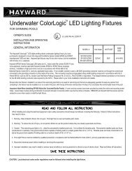
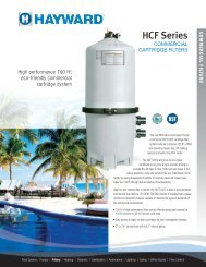
How a Heat Pump Works<br />
C<br />
TXV<br />
A<br />
HEAT<br />
FROM<br />
AIR<br />
E<br />
HOT<br />
WATER<br />
OUT<br />
D<br />
COLD<br />
WATER<br />
IN<br />
B<br />
AIR COIL (EVAPORATOR)<br />
COMPRESSOR<br />
WATER HEAT EXCHANGER<br />
(CONDENSER)<br />
The heat pump takes heat from the environment and uses it to heat the pool water. During heat pump operation,<br />
high temperature, high-pressure sub cooled liquid Refrigerant (A) is throttled by Metering Device (TXV) and<br />
turned into low temperature, low-pressure saturated liquid (B). The two-phase Refrigerant flows through the Air<br />
Coil (Evaporator), where the liquid refrigerant evaporates into vapor by absorbing heat from the surrounding<br />
air. At the outlet of the Air Coil (Evaporator) it becomes a low temperature, low-pressure superheated vapor<br />
(C). The Compressor receives this flow at the suction line (D), and compresses it into a high temperature, high<br />
pressure superheated vapor, which is discharged from the Compressor (E) and flows into the Water Heat<br />
Exchanger (Condenser). The heat carried by the flow is then released to the surrounding water from the pool. At<br />
the same time, the high temperature, high-pressure superheated vapor is then condensed back to high-pressure<br />
sub cooled liquid (A), which completes the cycle. The water, which is being forced through the Water Heat<br />
Exchanger (Condenser) by the pool pump, is heated as it passes through.<br />
Becoming Familiar with Your Heat Pump<br />
Heat Pump Protection Features<br />
<strong>Hayward</strong> heat pumps are equipped with safeguards that will stop operation to protect the unit in case of the<br />
following events:<br />
• Excessively high refrigerant pressure<br />
• Excessively high water temperature<br />
• Loss of refrigerant<br />
• Fan Motor Failure<br />
• Evaporator Freeze-up<br />
• Low Ambient Temperature<br />
USE ONLY HAYWARD GENUINE REPLACEMENT PARTS<br />
Pomona, CA Clemmons, NC Nashville, TN<br />
Tel: 908.351.5400 www.haywardpool.com
Page 7 of 24 HEATPRO HEAT PUMP HP13023772 Rev: B<br />
High / Low Refrigerant Pressure Switches<br />
• The high-pressure switch senses the refrigerant pressure in the sealed refrigeration system and turns<br />
the heat pump off if the operating pressure exceeds the normal pressure. The heat pump will<br />
automatically reset the switch after the system pressure drops back to normal operating pressure. The<br />
display will show “HI”, if this switch is tripped.<br />
• The low-pressure switch senses the refrigerant pressure in the sealed refrigeration system to protect<br />
against certain conditions that could be detrimental to compressor life. The switch turns the heat<br />
pump off in the event of loss of refrigerant, fan motor failure, evaporator freeze-up, or airflow<br />
blockage. The heat pump will automatically reset the switch after the system pressure rises to the<br />
normal operating pressure. The display will show “LP”, if this switch is tripped.<br />
Water Pressure Switch<br />
Water pressure causes the Water Pressure Switch contacts to close. Insufficient water pressure will allow these<br />
contacts to open, and turn the heat pump off. The display will read “PS” if the water pressure is not sufficient.<br />
Time Delay<br />
All models use a 5-minute time delay to prevent repeated tripping of the compressor thermal overload, which is<br />
caused by attempting startup before system refrigerant pressures are equalized. Any interruptions, outside of<br />
power loss, will result in a 5-minute time delay.<br />
Low Ambient Temperature<br />
If the air outside the heat pump is not warm enough the heat pump will not operate. The actual point at which<br />
the unit will cease operating due to low temperature varies depending on which model is purchased, current<br />
weather conditions, and the amount of sunlight reaching the heat pump. The shutdown can occur anywhere<br />
within a wide range of temperatures, near 50°F (10°C). This is not a “fixed” range. Climate conditions, sunlight,<br />
and various models respond differently to low ambient temperature. Low outside air temperatures will activate<br />
the systems defrost function. The heat pump will run for 15 minutes to defrost the evaporator coil at which time<br />
the control will check the temperature to see if the coil has warmed up sufficiently to return to normal operation.<br />
The control will run through three cycles checking the coil temperature, to try and return to normal operation,<br />
before it will shut the unit down completely for 2 hours (display will show “dEF”). After the 2-hour wait the<br />
unit will restart to check the temperature and try to resume normal operation. The heat pump control will<br />
continue this cycle until the evaporator is defrosted.<br />
USE ONLY HAYWARD GENUINE REPLACEMENT PARTS<br />
Pomona, CA Clemmons, NC Nashville, TN<br />
Tel: 908.351.5400 www.haywardpool.com
Page 8 of 24 HEATPRO HEAT PUMP HP13023772 Rev: B<br />
Clearance<br />
A minimum of 2 feet (.6 m) of clearance from walls, shrubbery, equipment, etc. is required around the entire<br />
heat pump. This allows for ample air intake. A minimum of 6 feet (2 m) of clearance above the heat pump is<br />
required to prevent re-circulation of air. We recommend NOT placing the unit underneath eaves, decks, or<br />
porches, as this causes re-circulation of air.<br />
RE-CIRCULATION OF AIR BACK<br />
INTO THE PUMP WILL<br />
GREATLY REDUCE ITS EFFICIENCY<br />
Roof Run-Off<br />
NOTICE - Make sure the heat pump is not located where large amounts of water may run-off from the roof<br />
into the unit. Sharp sloping roofs without gutters will allow massive amounts of rainwater, mixed with debris<br />
from the roof to be forced through the unit. This will clog, damage, and corrode the unit.<br />
NOTE: A gutter or down spout may need to be installed to protect the heat pump.<br />
Drainage and Condensation<br />
THE HEAT PUMP GENERATES WATER CONDENSATION DURING NORMAL OPERATION.<br />
THIS SHOULD NOT BE MISTAKEN FOR A LEAK IN THE UNIT.<br />
A drain hole is provided in the in base pan on the side of the unit opposite the controls for adequate removal of<br />
condensation and rainwater. Condensation will be produced by the evaporator coil while the unit is running and<br />
drain at a steady rate, usually 3 to 5 gallons per hour, depending upon ambient air temperature and humidity.<br />
The more humid the ambient air, the more condensation will be produced. If drainage is above this range during<br />
operation or if water continues to drain from the base when the heat pump is not in operation for more than an<br />
hour, a leak in the internal plumbing may have occurred. The troubleshooting section provides<br />
recommendations if a leak is suspected.<br />
NOTICE: Keep the drain hole clear of debris and clean it regularly to remove any obstruction.<br />
USE ONLY HAYWARD GENUINE REPLACEMENT PARTS<br />
Pomona, CA Clemmons, NC Nashville, TN<br />
Tel: 908.351.5400 www.haywardpool.com
Page 9 of 24 HEATPRO HEAT PUMP HP13023772 Rev: B<br />
NOTICE<br />
Make sure there are no sprinkler heads near the heat pump that will spray on or into the unit.<br />
Sprinkler damage is not covered under the warranty agreement.<br />
Make sure that sprinklers are placed at a sufficient distance away, so that normal wind will not<br />
carry the mist to the heat pump.<br />
The heat pump is designed to handle the wettest weather conditions that are typical of rain and high humidity.<br />
Sprinkler heads force high-pressure water into the unit from the side at an odd angle. Many sprinkler systems<br />
are connected to a well system, whose water is high in minerals, sulphur, and other aggressive contaminates that<br />
will leave a build up on the evaporator coils and electronics causing corrosion and hampering efficiency. If the<br />
installed location is within 15 miles of the coast, salt may also be in the well water.<br />
NOTICE- If in an oceanfront area, the heat pump should be placed out of direct spray of sand and salt.<br />
This will clog, damage, and corrode the unit, which will void the warranty. You may also consider protecting<br />
the unit by planting shrubbery or installing a privacy fence between the unit and the prevailing beachfront wind.<br />
NOTICE – Damage caused by sand or salt spray will void the warranty.<br />
POOL COVERS ARE STRONGLY RECOMMENDED<br />
Using a Pool Cover<br />
A pool loses heat in several ways and testing shows that evaporative cooling (the cooling effect created by<br />
water evaporating from the surface of the pool) accounts for approximately 75% of a pool’s heat loss. However,<br />
if a pool is covered when not in use, most evaporative cooling can be prevented. If the pool temperature is to be<br />
maintained, the pool heating system must replace the heat lost, therefore the use of a pool cover can offer<br />
dramatic savings in energy consumption. The cover’s approximate effect on pool losses is illustrated in the table<br />
below:<br />
Source of Heat Loss POOL UNCOVERED (USED 12HRS/DAY) POOL COVERED<br />
Evaporative Cooling 75% 30%<br />
Convection loss to air 15% 10%<br />
Ground loss (dry earth) (Negligible – less than 1%) (Negligible)<br />
Re-radiation to environment 9% 9%<br />
Make-up water 1% 1%<br />
Total 100% 50% of uncovered pool losses<br />
As the table shows, a pool cover that reduces evaporative cooling can reduce the heat lost from a pool by<br />
approximately 50% (which also reduces your power consumption by 50%).<br />
USE ONLY HAYWARD GENUINE REPLACEMENT PARTS<br />
Pomona, CA Clemmons, NC Nashville, TN<br />
Tel: 908.351.5400 www.haywardpool.com
Page 10 of 24 HEATPRO HEAT PUMP HP13023772 Rev: B<br />
Operating the HeatPro Heat Pump<br />
Start-Up Instructions<br />
NOTICE- Do not use this heat pump if any part has been flooded or submerged. Immediately call a qualified<br />
technician to inspect and replace any part of the heat pump control system that has been under water. Failure to<br />
do so will cause property damage.<br />
Before proceeding, MAKE CERTAIN there are no air or water leaks in any plumbing connections or piping<br />
and water flow is within the proper flow rate ranges. The proper flow ranges for ALL <strong>Hayward</strong> HeatPro Heat<br />
Pumps are a minimum of 30 GPM and a maximum of 75 GPM.<br />
NOTE: Damage caused by flow rates outside this range will void the warranty.<br />
CAUTION - Keep all objects off the top of the heat pump. Blocking airflow could damage the unit<br />
and will void the warranty.<br />
Start-Up Procedures<br />
After completing the electrical and piping connections to the pool heater, follow the procedures outlined below<br />
to ensure that the pool heat pump is functioning properly.<br />
1. Apply power to the pool heater by plugging in the non-fused disconnect block or moving the circuit<br />
breaker to the “ON” position.<br />
2. Place the pool heater thermostat in the “Standby” mode.<br />
3. With the pool filter pump operating properly, push the “POOL” button to activate the unit and then set<br />
the pool Heat Pump thermostat to the desired temperature.<br />
4. Allow 5 Minutes for the Heat Pump to start.<br />
5. When the unit starts, confirm that air is being discharged upward from the unit and the air is cooler than<br />
the ambient air.<br />
6. Allow the Heat Pump to operate for 10-15 minutes in order for system pressure to stabilize.<br />
7. If Heat Pump fails to start:<br />
a) Check water flow<br />
b) Ensure that power is On<br />
c) Refer to Performance Monitoring Section of this <strong>Manual</strong><br />
USE ONLY HAYWARD GENUINE REPLACEMENT PARTS<br />
Pomona, CA Clemmons, NC Nashville, TN<br />
Tel: 908.351.5400 www.haywardpool.com
Page 11 of 24 HEATPRO HEAT PUMP HP13023772 Rev: B<br />
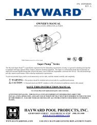
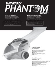
Becoming Familiar with HeatPro Heat Pump Controls<br />
Display Window<br />
Up Arrow Button<br />
Down Arrow Button<br />
Time Clock<br />
Override Button<br />
(Optional)<br />
Spa Button<br />
(Optional)<br />
Run Light<br />
Pool Button<br />
Heat Pump Control Panel<br />
Display Window (All Models)<br />
Up Arrow Button (All Models)<br />
Down Arrow Button (All Models)<br />
Pool Button (All Models)<br />
Spa Button (All Models except HP11003T)<br />
Run Light (All Models)<br />
Time Clock Override Button (Model<br />
HP2100TCO3T only)<br />
When power is supplied to the unit, the display will either show<br />
temperature (in degrees F or C), diagnostic code (such as<br />
“rhd”), or scrolling dots.<br />
Raises the heat pump temperature set point.<br />
Lowers the heat pump temperature set point.<br />
Activates the pool function of the controller.<br />
Activates the spa function of the controller.<br />
Indicates the unit is operating normally and the thermostat is<br />
making a demand for heat.<br />
Activates the time clock override function of the controller.<br />
USE ONLY HAYWARD GENUINE REPLACEMENT PARTS<br />
Pomona, CA Clemmons, NC Nashville, TN<br />
Tel: 908.351.5400 www.haywardpool.com
Page 12 of 24 HEATPRO HEAT PUMP HP13023772 Rev: B<br />
Control <strong>Operation</strong><br />
Dual Thermostat (Models HP6003T, HP21003T, HP21203T)<br />
On/Off:<br />
To enter Standby mode:<br />
To exit Standby mode:<br />
Mode Selection:<br />
Run Indicator Light:<br />
Temperature Set point:<br />
Adjust the set point:<br />
To display the set point:<br />
This control does not have a true on/off feature. The unit uses standby mode<br />
instead. Scrolling dots in the display indicate standby. Standby mode serves two<br />
functions. (1) It serves as an “off” mode, which keeps the heat pump from<br />
transferring heat into your pool water. (2) Standby allows a pool owner with<br />
remote controlling systems, such as Goldline, to maintain pool and spa<br />
temperatures via the remote.<br />
If pool mode is active (indicated by the green led over the pool button), press<br />
the pool button once. Rolling dots should appear on the display. If spa mode is<br />
active (indicated by the green led over the spa button), press the spa button<br />
once. Rolling dots should appear on the display.<br />
Press either the pool or spa mode button.<br />
Select the desired mode of operation (spa or pool) by using the POOL / SPA<br />
buttons. A green LED above the buttons designates the active mode. When the<br />
pool mode is active, any displays or adjustments apply only to the pool mode.<br />
Adjustments for spa mode must be made while the spa button is activated. A<br />
user can switch between modes without turning the control to standby first.<br />
Shows the unit is operating normally and the thermostat is making a demand for<br />
heat.<br />
Pool and spa mode range is 50-104°F (21-40°C).<br />
Continuing to hold the up or down arrow button will adjust the set point value<br />
until the desired set point is reached. When the desired value has been reached,<br />
release the button. The new set point will flash to indicate a new value has<br />
been recognized and the display will revert back to water temperature as<br />
indicated by a steady display.<br />
Press and release the up or down arrow button once to display the current set<br />
point for 3 seconds. For help with this type of control, refer to<br />
Troubleshooting Guide with Digital Control.<br />
USE ONLY HAYWARD GENUINE REPLACEMENT PARTS<br />
Pomona, CA Clemmons, NC Nashville, TN<br />
Tel: 908.351.5400 www.haywardpool.com
Page 13 of 24 HEATPRO HEAT PUMP HP13023772 Rev: B<br />
Single Thermostat (Model HP11003T)<br />
Display:<br />
On/Off:<br />
To enter standby mode:<br />
To exit standby mode:<br />
Run Indicator Light:<br />
Temperature Set point:<br />
Adjust the set point:<br />
When power is supplied to the unit, the display will either show temperature,<br />
diagnostic code (such as “rhd”), or scrolling dots.<br />
This control does not have a true on/off feature. The unit uses standby mode<br />
instead. Rolling dots in the display indicate standby. Standby mode serves two<br />
functions. (1) It serves as an “off” mode, which keeps the heat pump from<br />
transferring heat into your pool water. (2) Standby allows a pool owner with<br />
remote controlling systems, such as Goldline, to maintain pool temperature via the<br />
remote.<br />
Press the pool button once. Scrolling dots should appear on the display.<br />
Press the pool mode button.<br />
Shows the unit is operating normally and the thermostat is making a demand for<br />
heat.<br />
Pool mode range is 50-104°F (21-40°C).<br />
Continuing to hold the up or down button will scroll the set point value until the<br />
desired set point is reached. When the desired value has been reached, release the<br />
button. The new set point will flash to indicate a new value has been recognized<br />
and the display will revert back to water temperature as indicated by a steady<br />
display.<br />
Note: The temperature reading displayed when the unit is in operation (run indicator light is present) displays<br />
the current water temperature.<br />
To display the set point: Pressing and releasing the Temperature Set up or down button once will display the<br />
current set point for 3 seconds. For help with this type of control, refer to Troubleshooting Guide with Digital<br />
Control.<br />
TCO Function (Model HP2100TCO3T)<br />
Time Clock Override (TCO):<br />
TCO provides a method of maintaining the pool temperature when a time clock has the pool filter pump turned<br />
off. The TCO function then controls the pool filter pump. TCO will automatically turn the pool filter pump on<br />
after 2 hours of “off time”. It will run the filter pump for 10 minutes while monitoring the water temperature. If<br />
there is more than a 2°F (1°C) difference between the set point and the actual pool temperature the heat pump<br />
will energize and continue to run until the set point is satisfied.<br />
NOTE: The 2-hour TCO checking interval cannot be adjusted.<br />
USE ONLY HAYWARD GENUINE REPLACEMENT PARTS<br />
Pomona, CA Clemmons, NC Nashville, TN<br />
Tel: 908.351.5400 www.haywardpool.com
Page 14 of 24 HEATPRO HEAT PUMP HP13023772 Rev: B<br />
A user may temporarily override the TCO. An example would be if the pool were to be used between 9:00 and<br />
10:00 pm. The control may be programmed to energize the filter pump, which will engage the heat pump to<br />
maintain the pool temperature. This is a temporary measure that can be initiated in 30- minute increments, for a<br />
period up to 9.5 hours.<br />
Programming for Time Clock Override:<br />
1) Push and hold TC OVRD Button – Display will read “P0.0”<br />
2) Push up (RED) button – display will read “P0.5” and the TC OVRD light will be on.<br />
Note: Each time the up or down arrow button is pressed, the display will increase or decrease in “.5”<br />
increments. Each increment equals 30 minutes, up to 9.5 hours (P9.5) maximum<br />
3) Push down (BLUE) button to decrease the temporary override time. Continue decreasing the time until<br />
reaching “P0.0” to turn the override off.<br />
Example of typical TCO cycle: When the time clock turns off the filter pump, a “PS” will show on the<br />
display. A timer starts inside the controller. After 2 hours, the heat pump will start the filter pump to circulate<br />
water. “PS” is removed from the display and if a demand for more heat is made, the heat pump goes back to<br />
normal operation. The 2-hour timer is reset and the cycle will start over. For help with this type of control,<br />
refer to Troubleshooting Guide with Digital Control.<br />
Changing Temperature Display (All Models):<br />
The control will display temperatures in either degrees Fahrenheit or Celsius. To change the temperature<br />
display, place the heat pump in “Stand-By” mode so that the scrolling dots appear on the screen. Press and<br />
hold both the pool button and the down arrow button for two seconds and release. Place the heat pump back in<br />
pool or spa mode and the temperature change will be displayed. When viewing the temperature in degrees<br />
Fahrenheit only the numeric temperature is displayed, but when viewing degrees Celsius the control will<br />
display the numeric temperature followed by a lower case “c”.<br />
Lock Out Feature (All Models):<br />
A lock out function is provided to keep the temperature set point from being changed. To engage this function<br />
in the pool or spa mode press the up arrow button, down arrow button and pool button at the same time and<br />
hold for 2 seconds. The control display will read “LOC” while the lock out function is engaged. To exit the<br />
lock out function in pool or spa mode press the up arrow button, down arrow button and pool button at the<br />
same time.<br />
Defrost Function (All Models):<br />
This function is provided to prevent the evaporator coil from freezing up when the outside air temperature is<br />
near 50°F (10°C). There is no exact temperature at which this function will operate, as each unit will vary<br />
depending upon the surrounding conditions and outside air temperature. This time period will vary from 15<br />
minutes to several hours depending on the outside air conditions.<br />
USE ONLY HAYWARD GENUINE REPLACEMENT PARTS<br />
Pomona, CA Clemmons, NC Nashville, TN<br />
Tel: 908.351.5400 www.haywardpool.com
Page 15 of 24 HEATPRO HEAT PUMP HP13023772 Rev: B<br />
Maintenance<br />
Water Chemistry<br />
Proper chemical balances are necessary for sanitary swimming conditions as well as ensuring your heat pump’s<br />
long life.<br />
Sanitizing Equipment<br />
Sanitizers, if used, MUST be installed downstream of the heat pump (in the return line to the pool) and a check<br />
valve installed in a manner that will not allow the raw chlorine to drain back to the heat pump when the water<br />
filter pump is off. This will prolong the overall life of the heat exchanger and the heat pump. DO NOT POUR<br />
CHEMICALS DIRECTLY INTO THE SKIMMER.<br />
Inspection and Service<br />
<strong>Hayward</strong> HeatPro heat pumps are designed and constructed to provide long performance life when installed and<br />
operated properly under normal conditions. Periodic inspections are important to keep your heat pump running<br />
safely and efficiently through the years.<br />
Keep all objects off the top of the heat pump. Blocking airflow could damage the unit and void the<br />
warranty.<br />
Owner Inspection<br />
<strong>Hayward</strong> recommends that you inspect your heat pump on a seasonal basis and especially after significant<br />
weather events. Refer to the sections of this <strong>Manual</strong>: “Clearance”, “Roof Run-Off”, “Drainage and<br />
Condensation” for proper inspection.<br />
Professional Inspection<br />
WARNING - RISK OF ELECTRIC SHOCK OR ELECTROCUTION. Before servicing heat pump or<br />
motor, disconnect ALL electrical power. An EPA Certified service technician MUST perform inspection.<br />
Note: <strong>Hayward</strong> recommends annual equipment inspections.<br />
Note: Never use high-pressure water to clean evaporator coil fins, as this will cause damage to the coil.<br />
Summertime Shutdown<br />
For certain areas during the summer months, when the heat pump is not needed, you can place the heat pump in<br />
standby mode.<br />
End of Season (Winterizing)<br />
Failure to properly winterize heat pump may result in serious equipment damage. Freeze damage is NOT<br />
covered under the heat pump warranty.<br />
USE ONLY HAYWARD GENUINE REPLACEMENT PARTS<br />
Pomona, CA Clemmons, NC Nashville, TN<br />
Tel: 908.351.5400 www.haywardpool.com
Page 16 of 24 HEATPRO HEAT PUMP HP13023772 Rev: B<br />
While the plumbing connections are in the winterized condition (not fully tightened), it is imperative that the<br />
pool / spa water is NOT circulated through the heat pump. Loss of water through loose plumbing connections<br />
may result in damage to circulating pump, pool / spa structure and / or other equipment.<br />
Many pool service companies offer “Winterizing” assistance. <strong>Hayward</strong> recommends using a professional<br />
for this procedure.<br />
• Perform the cleaning procedures recommended above.<br />
• Disconnect the power supply (usually at the circuit breaker in your house).<br />
Cover the heat pump to protect it from snow and water, which may freeze and damage the unit. If the pool is<br />
being closed for the winter, BE ABSOLUTELY CERTAIN TO DISCONNECT THE HEAT PUMP FROM<br />
THE UNIONS AND DRAIN ALL WATER LINES. A drain plug is provided on the bottom water connection<br />
on the heat exchanger (see figure below). Remove all excess water.<br />
Some heat pump owners desire their pool to be heated during the winter months. This is possible when daytime<br />
temperatures are above the low ambient temperature (near 50°F [10°C]) for most of <strong>Hayward</strong>’s heat pumps.<br />
If temperatures fall below freezing, be certain to keep the pool filter pump operating continuously to prevent<br />
freeze damage.<br />
Performance Maintenance and Troubleshooting<br />
Service Procedures<br />
Before Calling For Service<br />
If there appears to be a problem, refer to the troubleshooting section on the following pages.<br />
1. Ensure the swimming pool filtration system is turned on.<br />
2. Ensure the main power circuit on.<br />
3. Verify that the heat pump is not in stand-by mode (pool or spa indicator light is illuminated).<br />
4. Ensure that the heat pump thermostat set at a high enough level to enable the system to turn on.<br />
USE ONLY HAYWARD GENUINE REPLACEMENT PARTS<br />
Pomona, CA Clemmons, NC Nashville, TN<br />
Tel: 908.351.5400 www.haywardpool.com
Page 17 of 24 HEATPRO HEAT PUMP HP13023772 Rev: B<br />
5. Ensure the outside temperature is high enough to allow the unit to operate. <strong>Hayward</strong> heat pumps will not<br />
turn on when the outside air temperatures drop near 50°F (10°C).<br />
6. Ensure that the pump and skimmer baskets are clean; also ensure that the pool filter is clean and<br />
supplying proper water flow to the heat pump.<br />
7. If the heat pump is not able to maintain the desired temperature, depending on the time of the year, it<br />
may be necessary to adjust your pool filtration systems hours of operation (increase run time).<br />
8. If the heat pump does not appear to be heating, check the air temperature being blown out of the top. If<br />
the air coming out is cooler than the ambient air, the unit is functioning properly. If the two temperatures<br />
are the same, there may be a problem.<br />
Note: Use a solar blanket / cover on the surface of the pool in order to minimize heat loss.<br />
Check the Electronic Display:<br />
1. If diagnostic code “PS” is displayed, insufficient water flow may be the problem. Ensure that pool filter<br />
pump basket, skimmer basket and filter are clean.<br />
2. If diagnostic code “LP” is displayed, this may indicate that the outside temperature is too low (50-55°F<br />
[10-13°C]). When this occurs, the Heat Pump turns off automatically. When the outside air temperature<br />
rises sufficiently, the heat pump will automatically turn on.<br />
3. If diagnostic code “HI” is displayed, this may indicate that an insufficient water flow condition exists.<br />
Check that the pool pump strainer basket, skimmer basket and filter are clean. After checking these<br />
items, if the “HI” indicator is still displayed, contact your original equipment installer or service<br />
provider. If you do not have a service provider, a list of service providers may be found at<br />
www.haywardnet.com/locator.<br />
USE ONLY HAYWARD GENUINE REPLACEMENT PARTS<br />
Pomona, CA Clemmons, NC Nashville, TN<br />
Tel: 908.351.5400 www.haywardpool.com
Page 18 of 24 HEATPRO HEAT PUMP HP13023772 Rev: B<br />
Troubleshooting<br />
Circuit Breakers: If it is suspected that a circuit breaker is tripped, turn the breaker to the “Off” position and<br />
then back to the “On” position. Visually checking the breaker is “On” is inadequate, as some switches move<br />
only a short distance when tripped. Toggle the switch to “Off” then “On” every time you suspect the breaker is<br />
tripped.<br />
General Troubleshooting Guide for <strong>Hayward</strong> HeatPro Heat Pump<br />
Problem Possible Cause Possible Solution(s)<br />
No power to unit<br />
Make sure power is on.<br />
Breaker is tripped<br />
Check the breaker / see note above<br />
Thermostat not turned up<br />
high enough<br />
Turn thermostat up until unit comes on<br />
5 minute delay timer still<br />
running<br />
Be sure the 5 minute delay has passed<br />
Unit is not operating.<br />
Low water flow<br />
Make sure filter is clean<br />
Make sure filter pump is on<br />
Unhook cleaning devices (skimmers, crawlers, etc.)<br />
Outside temperature too low<br />
Check outside ambient temperature or wait for<br />
warmer temperatures to operate. (refer to Operating<br />
section)<br />
Fan not functioning<br />
Call Pool Service Provider.<br />
Heat pump is running but<br />
is not heating “Run” light<br />
does not come on.<br />
Heat pump runs<br />
continually<br />
Heat pump is cycling (on /<br />
off too quickly)<br />
Water is coming from<br />
bottom of unit<br />
Check output air temperature<br />
to input air temperature.<br />
Differential should be<br />
between 5 and 12 ºF<br />
System Component failure.<br />
Thermostat set too high<br />
Electrical component failure<br />
Bad valve or improper water<br />
flow<br />
Low refrigerant, low ambient<br />
temp, or high humidity with<br />
low ambient temp<br />
Condensation<br />
Possible water leak<br />
Low ambient air temperature. Allow outside air<br />
temperature to exceed 60ºF, and then re-check.<br />
Call Pool Service Provider.<br />
Turn thermostat down<br />
Turn off the filter pump. If the unit is still running<br />
after 2 minutes, turn off the power to the unit and call<br />
Pool Service Provider.<br />
Check valve settings and ensure water flow is<br />
sufficient (is the filter pump running continually?) If<br />
heat pump continues to cycle, turn unit off to prevent<br />
compressor damage.<br />
Check evaporator coil for severe frost. Turn unit off to<br />
prevent compressor damage.<br />
If heat pump continues to cycle, turn unit off to<br />
prevent compressor damage- and call Pool Service<br />
Provider.<br />
This is normal and there is no reason to be concerned<br />
Turn the unit off for several hours, but leave the filter<br />
pump running continuously. If water discharge<br />
ceases, then it is only condensation. Otherwise there is<br />
a possible leak.<br />
USE ONLY HAYWARD GENUINE REPLACEMENT PARTS<br />
Pomona, CA Clemmons, NC Nashville, TN<br />
Tel: 908.351.5400 www.haywardpool.com
Page 19 of 24 HEATPRO HEAT PUMP HP13023772 Rev: B<br />
Display diagnostic codes - Troubleshooting Guide for <strong>Hayward</strong> HeatPro Heat Pump<br />
Display Problem Possible Cause Solution<br />
(Blank)<br />
No power to heat<br />
pump<br />
Faulty electrical<br />
component<br />
Tripped circuit breaker/<br />
no power supply<br />
Check breaker and ensure that the unit is properly<br />
installed.<br />
Call Pool Service Provider.<br />
★ Unit will not turn on 5-minute delay Wait 5 minutes<br />
PS<br />
Water Pressure<br />
Switch<br />
Low or no water flow<br />
LP Low Pressure Switch Air flow obstruction<br />
Check water flow to heat pump<br />
Clean the filter<br />
Make sure all valves are open and bypass valve is<br />
closed<br />
Ensure pool filter pump is on<br />
Normal operation for TCO function<br />
Turn off fountains, etc.<br />
Perform cleaning procedures described in this manual.<br />
Call Pool Service Provider.<br />
Check water flow to heat pump. .<br />
Low water flow<br />
Clean the filter<br />
Make sure all valves are open and bypass is closed.<br />
HI High Pressure Switch<br />
Ensure pool filter pump is on and turn off fountains.<br />
Set unit to “ACP” if the unit has the heat / cool option.<br />
High water temp<br />
Refer to text on HP3100 control board.<br />
Check pool temp. Wait until pool needs heat.<br />
Call Pool Service Provider.<br />
SH Temperature sensor Failure Call Pool Service Provider.<br />
OP Temperature sensor Failure Call Pool Service Provider.<br />
888 Thermostat reset Normal operation<br />
Temporary display. Shows for 1-2 seconds when the<br />
rhd<br />
Remote device is<br />
controlling the unit.<br />
unit is first turned on.<br />
Refer to owner’s manual of the remote device.<br />
If a remote device is not connected. Call Pool Service<br />
Provider.<br />
PST Push button stuck Release button is stuck. If button does not release. Call Pool Service Provider.<br />
PNL<br />
Control not receiving Control communication<br />
data from panel problem.<br />
Call Pool Service Provider.<br />
CEL<br />
Panel not receiving Control communication<br />
data from control problem.<br />
Call Pool Service Provider.<br />
CHC Board self-check error Board Failure Call Pool Service Provider.<br />
dEF Defrost Mode<br />
Frost build up on<br />
evaporator coil.<br />
No action required. Unit is defrosting automatically.<br />
cOP Coil Sensor Sensor Failure Call Pool Service Provider<br />
cSH Coil Sensor Sensor Failure Call Pool Service Provider<br />
USE ONLY HAYWARD GENUINE REPLACEMENT PARTS<br />
Pomona, CA Clemmons, NC Nashville, TN<br />
Tel: 908.351.5400 www.haywardpool.com
Page 20 of 24 HEATPRO HEAT PUMP HP13023772 Rev: B<br />
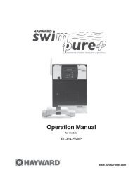
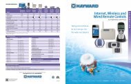
Heat Pump Replacement <strong>Parts</strong> Diagram<br />
CONTROL BOX FOR:<br />
HP6003T, HP11003T,<br />
HP21003T AND<br />
HP21203T<br />
CONTROL BOX FOR:<br />
HP2100TCO3T<br />
USE ONLY HAYWARD GENUINE REPLACEMENT PARTS<br />
Pomona, CA Clemmons, NC Nashville, TN<br />
Tel: 908.351.5400 www.haywardpool.com
Page 21 of 24 HEATPRO HEAT PUMP HP13023772 Rev: B<br />
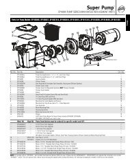
Heat Pump Replacement <strong>Parts</strong> List<br />
Item Part description HP21203T HP21003T HP2100TCO3T HP11003T HP6003T<br />
1 FAN TOP<br />
HPX01023502<br />
2 SIDE PANEL<br />
HPX01023503<br />
3 CONTROL BOX COVER<br />
HPX01023504<br />
4 CONTROL BOX<br />
HPX01023505<br />
5 CONTACTOR<br />
HPX1985<br />
6 CONTROL BOARD ASSY HPX26024139 HPX26024140 HPX26024138 HPX26024139<br />
7 INTERFACE BOARD<br />
HPX11024130<br />
8 WATER PRESSURE SWITCH<br />
HPX2181<br />
9 TRANSFORMER<br />
HPX11023693<br />
10 CAPACITOR HPX11024155<br />
HPX11024154<br />
11 BENT COIL with GUARD<br />
HPX24023929<br />
12 COMPRESSOR HPX11023911 HPX11024170<br />
HPX11024077<br />
13 CONDENSER<br />
HPX24023941<br />
14 COVER GASKET<br />
HPX05023549<br />
15 HPC CABLE (NS)<br />
HPX10023517<br />
16 FAN MOTOR, 1/3 HP<br />
HPX11023564<br />
17 FAN GUARD<br />
HPX01023561<br />
18 COMPRESSOR BLANKET (NS)<br />
HPX02024108<br />
19 -<br />
-<br />
20 FAN BLADE<br />
HPX15023562<br />
21 REPLACEMENT HP SWITCH<br />
HPX2186<br />
22 REPLACEMENT LP SWITCH<br />
HPX2179<br />
23 EXPANSION VALVE ASSY HPX15024023<br />
HPX15024026<br />
24 -<br />
-<br />
25 TEMPERATURE SENSOR<br />
HPX2169<br />
26 SCREW REPLACEMENT KIT (NS)<br />
HPXSCRKIT1<br />
27 COMPRESSOR MOUNT KIT (NS)<br />
HPX0054<br />
28 COMPRESSOR EL. PLUG (NS)<br />
HPX2223<br />
29 ELECTRICAL ENTRY PLUG<br />
HPX01023760<br />
30 DRAIN PLUG<br />
SPX4000FG<br />
31 FAN RUN CAPACITOR<br />
HPX11024151<br />
32 DEFROST SENSOR<br />
HPX11024169<br />
USE ONLY HAYWARD GENUINE REPLACEMENT PARTS<br />
Pomona, CA Clemmons, NC Nashville, TN<br />
Tel: 908.351.5400 www.haywardpool.com
Page 22 of 24 HEATPRO HEAT PUMP HP13023772 Rev: B<br />
NOTES:<br />
_____________________________________________________________________________<br />
_____________________________________________________________________________<br />
_____________________________________________________________________________<br />
_____________________________________________________________________________<br />
_____________________________________________________________________________<br />
_____________________________________________________________________________<br />
_____________________________________________________________________________<br />
_____________________________________________________________________________<br />
_____________________________________________________________________________<br />
_____________________________________________________________________________<br />
_____________________________________________________________________________<br />
_____________________________________________________________________________<br />
_____________________________________________________________________________<br />
_____________________________________________________________________________<br />
_____________________________________________________________________________<br />
_____________________________________________________________________________<br />
_____________________________________________________________________________<br />
_____________________________________________________________________________<br />
_____________________________________________________________________________<br />
USE ONLY HAYWARD GENUINE REPLACEMENT PARTS<br />
Pomona, CA Clemmons, NC Nashville, TN<br />
Tel: 908.351.5400 www.haywardpool.com
Page 23 of 24 HEATPRO HEAT PUMP HP13023772 Rev: B<br />
HAYWARD ® HEAT PUMP POOL HEATERS LIMITED WARRANTY<br />
The HAYWARD heat pump pool heater is warranted to be free of defects in materials and workmanship for a period of<br />
two (2) years for parts and (1) one year for labor. In the state of Florida, warranty labor is covered for (2) years. This<br />
warranty is applicable to the original location and owner only and is not transferable. The compressor component has a<br />
five (5) year limited warranty with parts and labor warranted the first two (2) years and parts only warranted in years<br />
three (3), four (4) and five (5). The titanium tube component of the heat exchanger has a ten (10) year warranty.<br />
HAYWARD will not void this warranty due to improper pool chemistry. This warranty is valid only if the product is<br />
installed according to the HAYWARD specifications.<br />
This warranty does not include refrigerant or other expendable materials, or services such as inspection, maintenance,<br />
or unnecessary service calls due to erroneous operational reports, external valve position, or electrical service. It also<br />
does not include the repair of damage due to negligence, accident, freezing, or other conditions beyond the normal<br />
intended use of the unit. This warranty is void if the product is repaired or altered in any way by any persons or<br />
agencies other than those authorized by HAYWARD, and is in lieu of all other warranties, expressed or implied,<br />
written or oral. There are no implied warranties of merchantability or fitness for a particular purpose that apply to this<br />
product. This warranty applies only within the continental USA. For warranty outside the continental USA, contact<br />
HAYWARD.<br />
At its option, HAYWARD will replace or repair any HAYWARD part that proves defective if such parts are returned<br />
to our factory, freight collect, within the warranty period. It is agreed that such replacement or repair is the exclusive<br />
remedy available from HAYWARD. Unless authorized by HAYWARD and performed by a factory authorized service<br />
center, HAYWARD is not liable for any labor involved in the removal of defective parts or the installation of<br />
replacement parts. HAYWARD is not liable for damages of any sort whatsoever, including incidental and<br />
consequential damages. <strong>Parts</strong> returned and services performed under terms of this warranty must be approved by<br />
HAYWARD. All parts returned under terms of this warranty will be repaired or replaced and returned transportation<br />
charges prepaid, by best and most economical means.<br />
This warranty applies to units shipped after July 14, 2008<br />
<strong>Hayward</strong> Pool Products, Inc.<br />
620 Division Street<br />
Elizabeth, NJ 07207<br />
Retain this Warranty Certificate in a safe and convenient location for your records<br />
USE ONLY HAYWARD GENUINE REPLACEMENT PARTS<br />
Pomona, CA Clemmons, NC Nashville, TN<br />
Tel: 908.351.5400 www.haywardpool.com
Page 24 of 24 HEATPRO HEAT PUMP HP13023772 Rev: B<br />
▼DETACH HERE: Fill out bottom portion completely and mail within 10 days of purchase/installation.<br />
USE ONLY HAYWARD GENUINE REPLACEMENT PARTS<br />
Pomona, CA Clemmons, NC Nashville, TN<br />
Tel: 908.351.5400 www.haywardpool.com