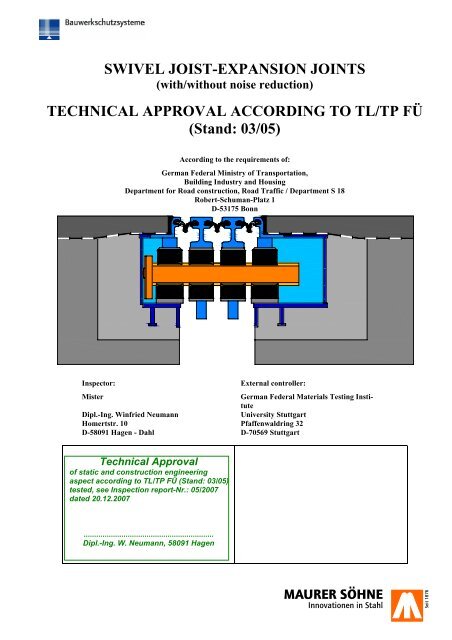
Technical Approval Swivel Joist Expansion Joints - Maurer Söhne ...
Technical Approval Swivel Joist Expansion Joints - Maurer Söhne ...
Technical Approval Swivel Joist Expansion Joints - Maurer Söhne ...

You also want an ePaper? Increase the reach of your titles
YUMPU automatically turns print PDFs into web optimized ePapers that Google loves.
SWIVEL JOIST-EXPANSION JOINTS<br />
(with/without noise reduction)<br />
TECHNICAL APPROVAL ACCORDING TO TL/TP FÜ<br />
(Stand: 03/05)<br />
According to the requirements of:<br />
German Federal Ministry of Transportation,<br />
Building Industry and Housing<br />
Department for Road construction, Road Traffic / Department S 18<br />
Robert-Schuman-Platz 1<br />
D-53175 Bonn<br />
Inspector:<br />
Mister<br />
Dipl.-Ing. Winfried Neumann<br />
Homertstr. 10 Pfaffenwaldring 32<br />
D-58091 Hagen - Dahl D-70569 Stuttgart<br />
External controller:<br />
German Federal Materials Testing Institute<br />
University Stuttgart<br />
<strong>Technical</strong> <strong>Approval</strong><br />
of static and construction engineering<br />
aspect according to TL/TP FÜ (Stand: 03/05)<br />
tested, see Inspection report-Nr.: 05/2007<br />
dated 20.12.2007<br />
..............................................................<br />
Dipl.-Ing. W. Neumann, 58091 Hagen
VERFASSER :<br />
BAUWERK : STRASSEN- UND WEGBRÜCKEN DATUM: 01.12.2007<br />
CONTENTS<br />
M A N U A L<br />
Chapter Title Page<br />
0. Field of Application 1<br />
1. Persons in charge 1<br />
1.1 Applicant and Operator 1<br />
1.2 Manufacturer of the expansion joint 1<br />
1.3 Manufacturer of special components 1<br />
1.4 Quality Assurance 2<br />
1.5 <strong>Approval</strong> and Tests 2<br />
1.6 Manufacturer’s declaration 2<br />
2. Description of the system 3<br />
2.1 General 3-4<br />
2.2 Type STW 4<br />
2.3 Type STP 5<br />
2.4 Force Transfer of the Wheel Loads 5-6<br />
2.5 Elastic support of joists 6<br />
2.6 Anchorage 6<br />
2.7 Sealing profile 6-7<br />
2.8 Noise reduction (optional) 7-8<br />
3. Hints for the user 9<br />
3.1 Checklist for Planning and Inspection 9<br />
3.2 Overview of the allowed movements determined within the scope of the <strong>Technical</strong> approval 10-12<br />
3.3 Additional regulatory framework for the use of rhombic elements 13-15<br />
3.4 Recess-sizes 16-18<br />
3.5 Anchoring powers 19<br />
4. Construction requirements for the technically approved expansion joints 20<br />
4.1 Allowed cross bar interspaces and the arrangement of the joints 20<br />
4.2 Arrangement of joists in the footway 21<br />
4.3 Factory provided corrosion protection 22<br />
5. Installation instructions 23<br />
5.1 Delivery 23<br />
5.2 Assembly and structural connection 23-26<br />
5.3 Anchoring in the cap area 26<br />
5.4 Procedure for bridges with steel carriageways 27<br />
5.5 Control of installation dimension 26-27<br />
5.6 Sealing of the structure 28<br />
5.7 Further information 29<br />
5.8 Site joints 30-32<br />
Appendix<br />
Certificate of acceptance / Installation record 33<br />
6. Information for maintenance, preservation and removal of wear and tear parts 34<br />
6.1 Accessibility 34<br />
6.2 Constructional Elements Subjected to Continuous Checking 35-36<br />
6.3 Replacing the sealing elements 36<br />
6.4 Replacing the wear and tear elements from the carriageway direction 37-38<br />
7. Construction plans and parts lists 39<br />
Appendix Seven drawings<br />
Inspection Report (2 pages)<br />
BAUTEIL : SCHWENKTRAVERSEN-DEHNFUGE DS160 BIS 1200<br />
BLOCK : UNTERLAGEN MIT REGELPRÜFVERMERK<br />
VORGANG : REGELPRÜFUNG NACH TL/TP FÜ (STAND: 03/05)<br />
ARCHIV NR.<br />
Regelprüfung<br />
Nr. 05/07 vom 20.12.07<br />
Diese Unterlagen sind Eigentum der MAURER SÖHNE GmbH & Co. KG. Jede Art der Vervielfältigung - auch auszugsweise - bedarf der Zustimmung.<br />
Formate und Inhalte sind urheberrechtlich geschützt!
VERFASSER :<br />
BAUWERK : STRASSEN- UND WEGBRÜCKEN DATUM: 01.12.2007<br />
0. Field of Application<br />
Due to the implementation of the Version 12/07 the hitherto valid Version of December 02, 2003 is now<br />
void.<br />
The technical approval covers Construction of frequently repeated methods of construction. Currently there<br />
are the following limitations of the range of use to be considered:<br />
- The carriageway may not exceed 10% of the transverse slope<br />
- The carriageway may not exceed 9% of the slope with the DS640 type and 6% of the slope with larger<br />
types<br />
- Allowed movements given by the Table 3.2 are to be considered.<br />
- According to the ground plan, direction changes of the joint design are allowed only with Type STW<br />
between<br />
- the lying carriageway outside cross bar (joist) and the cornice or footway cross bar<br />
- For noise reduction the use of rhombic elements is possible only between 60° ≤ α ≤ 120°.<br />
Deviations from the above limitations and subsequent specifications are possible, but they require however<br />
a test for each single case separately.<br />
1. Persons in charge<br />
1.1 Applicant and Operator<br />
MAURER SÖHNE GmbH & Co. KG<br />
Frankfurter Ring 193<br />
80807 Munich<br />
<strong>Technical</strong> Office Munich<br />
Dr. Ch. Braun, Mr. B. Volk<br />
1.2 Manufacturer of the expansion joint<br />
MAURER SÖHNE GmbH & Co. KG<br />
<strong>Technical</strong> Offices: Manufacturing sites Installation crews<br />
Frankfurter Ring 193<br />
80807 Munich<br />
Zum Holzplatz 2<br />
44536 Lünen<br />
Kamenzer Str. 53<br />
02994 Bernsdorf<br />
Frankfurter Ring 193<br />
80807 Munich<br />
Kamenzer Str. 53<br />
02994 Bernsdorf<br />
Frankfurter Ring 193<br />
80807 Munich<br />
Zum Holzplatz 2<br />
44536 Lünen<br />
Kamenzer Str. 53<br />
02994 Bernsdorf<br />
1.3 Manufacturer of special components<br />
See "The List of approved suppliers" in the appendix of the companies' work instruction QSA 1.810 in<br />
current version.<br />
BAUTEIL : SCHWENKTRAVERSEN-DEHNFUGE DS160 BIS 1200<br />
BLOCK : 1 - VERANTWORTLICHE SEITE: 1<br />
VORGANG : REGELPRÜFUNG NACH TL/TP FÜ (STAND: 03/05)<br />
ARCHIV NR.<br />
Regelprüfung<br />
Nr. 05/07 vom 20.12.07<br />
Diese Unterlagen sind Eigentum der MAURER SÖHNE GmbH & Co. KG. Jede Art der Vervielfältigung - auch auszugsweise - bedarf der Zustimmung.<br />
Formate und Inhalte sind urheberrechtlich geschützt!
VERFASSER :<br />
BAUWERK : STRASSEN- UND WEGBRÜCKEN DATUM: 01.12.2007<br />
1.4 Quality Assurance<br />
QS-System<br />
The quality management system meets the DIN EN ISO 9001 standards. It was certified by DVS-Zert.<br />
Monitoring<br />
The Monitoring is divided into external and internal supervision. The documents and working instructions<br />
that form the basis of this TECHNICAL APPROVAL will be tested on their compliance with these regulations.<br />
Responsible for the External Monitoring is the<br />
German Federal Materials Testing Institute of the University Stuttgart<br />
Pfaffenwaldring 32/ D-70569 Stuttgart<br />
1.5 <strong>Approval</strong> and Verifications<br />
<strong>Approval</strong>s for Welding<br />
Munich Factory "The Extensive Proof of Suitability" according to DIN 18800 Part 7, DIN 15018<br />
(DIN 18809 included in DIN 15018), DIN 4099 and DS 804<br />
Bernsdorf Factory<br />
"The Extensive Proof of Suitability" according to DIN 18800 Part 7, DIN 4099 and<br />
DS 804 (DIN 18809)<br />
Branch Lünen "The Extensive Proof of Suitability" according to DIN 18800 Part 7, DIN 18809,<br />
and DS 804<br />
<strong>Approval</strong> of Factory Welders<br />
The condition required to obtain an <strong>Approval</strong> is a Licence according to DIN EN 287-1.<br />
<strong>Approval</strong> of site Welders<br />
According to component demands, only welders with a valid Verification Certificate according to DIN EN 287-1<br />
and Concrete Reinforcement Steel Welder’s Verification according to DIN 4099 are deployed. The related verification<br />
is avaliable on the site.<br />
1.6 Producer's statement<br />
MAURER SÖHNE GmbH & Co. KG herewith declare<br />
•Compliance with the design conditions of all documents with the test certificates, listed in the index from 1.12.2007<br />
•Compliance with quality assurance standards listed in the supervision contract from 01 st April 2002.<br />
Munich, 01 st December 2007<br />
Company Management<br />
<strong>Technical</strong> Office<br />
BAUTEIL : SCHWENKTRAVERSEN-DEHNFUGE DS160 BIS 1200<br />
BLOCK : 1 - VERANTWORTLICHE SEITE: 2<br />
VORGANG : REGELPRÜFUNG NACH TL/TP FÜ (STAND: 03/05)<br />
ARCHIV NR.<br />
Regelprüfung<br />
Nr. 05/07 vom 20.12.07<br />
Diese Unterlagen sind Eigentum der MAURER SÖHNE GmbH & Co. KG. Jede Art der Vervielfältigung - auch auszugsweise - bedarf der Zustimmung.<br />
Formate und Inhalte sind urheberrechtlich geschützt!
VERFASSER :<br />
BAUWERK : STRASSEN- UND WEGBRÜCKEN DATUM: 01.12.2007<br />
2. Description of the system<br />
2.1 General<br />
The lamellas are bedded movably on the diagonally arranged carriageway-joists. Each joist acts as a supporting<br />
component of all the lamellas of an expansion joint.<br />
End stops limiting the movements of the lamellas can be designed, either one sided for both moving directions<br />
(normal case), or at both ends of the lamellas for one moving direction (special case). Depending on<br />
the operating condition, such construction can on the one hand (in the normal case) feature an extremely<br />
short cross bar box and at the counter bearing a long cross bar box, and on the other hand (in the special<br />
case) moderately long cross bar boxes on both sides.<br />
Due to superstructure movement the cross bars are distorted when moving through the swivel guide sliding<br />
bearings . The swivel movement causes an even distribution of the movement on individual joint gaps due<br />
to a fixed swivel point clearance.<br />
The load carrying and steering function is achieved simply without an additional steering mechanism<br />
within the ground plan by diagonally lying parallel aligned cross bars with the STP type and alternately<br />
aligned cross bars with the STW type.<br />
This steering of the swivel bar construction has the advantage of controlling the exact leverage. Unlike the<br />
leverage controlling, it is also possible to compensate the manufacturing tolerances and different temperature<br />
dilatations of the lamellas and edge beams through its push flexible swivel joints.<br />
The lamellas are slidable supported through trust rotary sliding bearings and springs with lateral guide bars<br />
in the cross bar direction. The bearing elements are twistingly mounted on the lamella resp. bearing holder<br />
at the vertical axis. Thereby their clearings are fixed.<br />
BAUTEIL : SCHWENKTRAVERSEN-DEHNFUGE DS160 BIS 1200<br />
BLOCK : 2 – BESCHREIBUNG DES SYSTEMS SEITE: 3<br />
VORGANG : REGELPRÜFUNG NACH TL/TP FÜ (STAND: 03/05)<br />
ARCHIV NR.<br />
Regelprüfung<br />
Nr. 05/07 vom 20.12.07<br />
Diese Unterlagen sind Eigentum der MAURER SÖHNE GmbH & Co. KG. Jede Art der Vervielfältigung - auch auszugsweise - bedarf der Zustimmung.<br />
Formate und Inhalte sind urheberrechtlich geschützt!
VERFASSER :<br />
BAUWERK : STRASSEN- UND WEGBRÜCKEN DATUM: 01.12.2007<br />
Due to their great possibility of adaptability the MAURER swivel cross bar joints are preferred with very<br />
large and / or complex movings of the bridge constructions and by the space constraints of the available<br />
construction site for expansion joint construction.<br />
For very large movements the use of sviwel joist expansion joints is preferred for geometrical and economical<br />
reasons. This technical approval covers sviwel joist expansion joints with up to 975 mm allowed<br />
longitudinal construction movement. This maximum permissible value can be raised in individual cases<br />
through verification.<br />
Due to the special kinematics of MAURER sviwel joist expansion joints, they are also applicable for the<br />
pin radiancy form of expansion joint edge movement, and for complex overlaps of different movement<br />
directions and twists in three space axis x, y and z. In section 3.2 the presented maximum values are<br />
therefore the only limitation.<br />
For larger swivel joints the use of swivel joint construction is recommended due to the small gap dimensions.<br />
They are especially suitable for joints to steel bridges and for the replacement of multi plate roll<br />
sealing.<br />
.<br />
2.2 Model STW<br />
The cross bars are aligned alternately and that gives a different distance between the supports on each lamella.<br />
As the maximum distance of the cross bar is determinate, the same is true with the number of<br />
lamellas. All marginable displacements in the longitudinal joint direction are absorbed free of constraint.<br />
The border areas of the change-over out of the carriageway are supported with special cornice cross bars.<br />
The steering kinematics are composed of three carriageway cross bars arranged transverse to each other.<br />
The cross bars are sliding, supported in their longitudinal direction at the gap edge.<br />
BAUTEIL : SCHWENKTRAVERSEN-DEHNFUGE DS160 BIS 1200<br />
BLOCK : 2 – BESCHREIBUNG DES SYSTEMS SEITE: 4<br />
VORGANG : REGELPRÜFUNG NACH TL/TP FÜ (STAND: 03/05)<br />
ARCHIV NR.<br />
Regelprüfung<br />
Nr. 05/07 vom 20.12.07<br />
Diese Unterlagen sind Eigentum der MAURER SÖHNE GmbH & Co. KG. Jede Art der Vervielfältigung - auch auszugsweise - bedarf der Zustimmung.<br />
Formate und Inhalte sind urheberrechtlich geschützt!
VERFASSER :<br />
BAUWERK : STRASSEN- UND WEGBRÜCKEN DATUM: 01.12.2007<br />
2.3 Model STP<br />
The cross bars are aligned parallel and that gives an equal supporting distance on each lamella. So the<br />
maximum number of lamellas is not limited and is applicable right up to the largest extension paths in<br />
bridge construction.<br />
Out of the carriageway there is a guiding cross bar, aligned at right angle to the gap axis in the central<br />
position of the gap.<br />
The steering kinematic is set up through this guiding cross bar, positioned at right angle to the lamellas and<br />
clearly angular to the carriageway cross bars arranged to the lamellas. The cross bars are sliding, supported<br />
in their longitudinal direction at the gap edge.<br />
With the use of a swivelling directional cross bar and without the use of a one axis movable footway cross<br />
bar, it is possible to combine all the movements of carriageway change over in any order according to the<br />
allowed movements from section 3.2, i.e. the fixing of of the bridge end bearing to a one way movement<br />
direction is unnecessary in such a case. On the contrary, the use of a directional cross bar without the<br />
swivelling part is possible for right angle bridge ends (α 2 =90°±3°). But in such a case, each of the superstructure<br />
ends has to be guided through a minimal one-axis flexible bearing.<br />
2.4 Force Transfer of the Wheel Loads<br />
Vehicles travelling over the superstructure section, transmit vertical and horizontal forces to the bar. The<br />
section forces, which appear as a result of eccentric wheel loads are transmitted to the bar by means of the<br />
centre beam and via welding connections to the bar. From the bars they are transmitted via bearing elements<br />
and control springs to the joint's edges.<br />
The cross bars, which bridge joint gaps are positioned diagonal to the lamella. Sliding bearings and sliding<br />
Springs respectively, positioned above or below the cross bars encompass the cross bar with lateral guiding<br />
bars. In this way forces can be transmitted diagonally to the cross bar.<br />
BAUTEIL : SCHWENKTRAVERSEN-DEHNFUGE DS160 BIS 1200<br />
BLOCK : 2 – BESCHREIBUNG DES SYSTEMS SEITE: 5<br />
VORGANG : REGELPRÜFUNG NACH TL/TP FÜ (STAND: 03/05)<br />
ARCHIV NR.<br />
Regelprüfung<br />
Nr. 05/07 vom 20.12.07<br />
Diese Unterlagen sind Eigentum der MAURER SÖHNE GmbH & Co. KG. Jede Art der Vervielfältigung - auch auszugsweise - bedarf der Zustimmung.<br />
Formate und Inhalte sind urheberrechtlich geschützt!
VERFASSER :<br />
BAUWERK : STRASSEN- UND WEGBRÜCKEN DATUM: 01.12.2007<br />
As a result of braking forces, the bearing elevation revolves. The displacements of the sliding bearings and<br />
the sliding springs on the bar, which occur due to revolving, affect propulsive forces in both bearing cushions.<br />
These produce via the big moment arm high return torque forces, which affect the high torsion stiffness<br />
bearing of the lamella attached to the cross bars.<br />
2.5 Elastic support of joists<br />
The lamellas on the joist as well as the joist at the structure's edges, are bedded spring-resilient on sliding<br />
bearings. A lift-off from the sliding bearing is prevented by means of a pre-stressed sliding spring that is<br />
arranged in the bearing holder underneath and in the joist-box.<br />
Through this elastic support the momentum of the wheels is damped when transferred to the absorb elements<br />
of the cross section or to the neighbouring anchor parts. The arrangement of the elastomer bearing<br />
elements between all relatively converging components prevents any metal-to-metal contact and assures at<br />
the same time high damping of noises in rubber rolls.<br />
The elastomer bearing elements allow rotations about all three space axis x, y and z, whereby for instance<br />
unplanned restraint forces on bearing points can be prevented.<br />
2.6 Anchoring<br />
Edge profiles are anchored with non stretchable anchor plates and welded round steel clamps in the concrete<br />
of the construction. The cross bar boxes have welded head bolt dowels to connect to neighbouring<br />
concrete. In steel bridges the edge construction is mounted on steel consoles or a support holder parallel to<br />
the end cross beam.<br />
2.7 Sealing profile<br />
The bulbous-shaped EPDM strip water- and pullout proof seal is installed in a claw in the edge beam and<br />
centre beams without the need for additional clamping bars. At the thickened places at the edge of the seal<br />
expansion joints a web is formed, which ends as a beaded rim. When the seal expansion joint is placed into<br />
the steel profile, the thickened part presses, using the wedging force, against the steel profile. By this<br />
means in addition to a form-locking connection, a friction-fitted Seal-/Steel profile contact is provided. At<br />
the same time the formed web with beaded rim acts as a lock which prevents jumping out in the case of<br />
dragging forces. The sealing element is set below the road surface level, and thus protected against direct<br />
wheel- or snowplough-contact.<br />
The bulbous edge section of the sealing element locks it in the steel claw and is capable of withstanding<br />
wheel pressure on any impurities (e.g. stones, grit, snow etc.). The sealing element adapts to different<br />
kinds of joint design and bridge cross sections.<br />
The admissible displacement of the sealing profile rectangular in the direction to the gap is 65 mm. With<br />
its preformed articulated section it is possible to move the strip seal in the direction of the carriageway<br />
without any appreciable strain. The admissible displacement in the direction to the gap of ± 40 mm causes<br />
a strain in the sealing profile.<br />
BAUTEIL : SCHWENKTRAVERSEN-DEHNFUGE DS160 BIS 1200<br />
BLOCK : 2 – BESCHREIBUNG DES SYSTEMS SEITE: 6<br />
VORGANG : REGELPRÜFUNG NACH TL/TP FÜ (STAND: 03/05)<br />
ARCHIV NR.<br />
Regelprüfung<br />
Nr. 05/07 vom 20.12.07<br />
Diese Unterlagen sind Eigentum der MAURER SÖHNE GmbH & Co. KG. Jede Art der Vervielfältigung - auch auszugsweise - bedarf der Zustimmung.<br />
Formate und Inhalte sind urheberrechtlich geschützt!
VERFASSER :<br />
BAUWERK : STRASSEN- UND WEGBRÜCKEN DATUM: 01.12.2007<br />
Sealing elements can be replaced from above with a pry bar when the individual gaps are ≥ 25 mm. If diamond<br />
elements are used for noise reduction, the individual gaps have to be ≥ 60 mm. The gap width can be<br />
enlarged by moving the lamellas.<br />
2.8 Noise reduction (optional)<br />
On bridges the noise radiates not only from the driving surface but also underneath and is often additionally<br />
amplified by the swinging impulses of the bridge superstructure. The noises on uneven road surface<br />
and on cross sections are sensed as especially disturbing.<br />
With the use of rhombic elements the tyres do not hit the steel edges rectangularly but diagonally against<br />
rounded tops and so a noticeable impact and noise reduction is achieved.<br />
The rhombic elements are attached to the underneath lamellas through punched welding. The rhombic<br />
elements tops project over the edges of the lamellas and don’t touch neighbouring lamellas or the edge<br />
profile. The elements partly cover the neighbouring gap of the joint without building a passing through gap<br />
on the joint. There are sinusoid cut-out edge plates welded on the edge profiles.<br />
BAUTEIL : SCHWENKTRAVERSEN-DEHNFUGE DS160 BIS 1200<br />
BLOCK : 2 – BESCHREIBUNG DES SYSTEMS SEITE: 7<br />
VORGANG : REGELPRÜFUNG NACH TL/TP FÜ (STAND: 03/05)<br />
ARCHIV NR.<br />
Regelprüfung<br />
Nr. 05/07 vom 20.12.07<br />
Diese Unterlagen sind Eigentum der MAURER SÖHNE GmbH & Co. KG. Jede Art der Vervielfältigung - auch auszugsweise - bedarf der Zustimmung.<br />
Formate und Inhalte sind urheberrechtlich geschützt!
VERFASSER :<br />
BAUWERK : STRASSEN- UND WEGBRÜCKEN DATUM: 01.12.2007<br />
This gives a noise reduction of approximately 7dB for cars and trucks compared to the usual joints made<br />
with lamellas crossed over rectangular to the gap (ε = 90°).<br />
By welded rhombic elements, the carriageway geometry is also changed. The influence on the wheel load<br />
spreading at the cross section construction was technically experimentally tested at the TU-Munich,<br />
Prüfamt Landverkehrswege with comparative analysis of results for the lamellas with and without rhombic<br />
elements. The truck wheel was put centric above the middle lamella and at the second line of the experiment<br />
between two lamellas. Additionally the load position of 5 different gap widths was tested.<br />
The results showed that the lamellas with and without the diamonds had to absorb almost the same wheel<br />
load. In present forms there are also none static relevant differences.<br />
All other known design concepts for carriageway cross sections have full validity for the rhombic variety<br />
too.<br />
The tests showed no differences in traffic security concerning the tyre grip between the constructions of<br />
lamellas with and without rhombic elements at non profiled surfaces.<br />
As the rhombic elements are hammer forged the driving surfaces obtain an additionally chequered structure.<br />
This provides a better grip between the wheel and the rhombic element and it is carried out as advancement<br />
of technical traffic security regardless of positive test results.<br />
As the rhombic elements are pouched welded, there is a non welded gap on the outer edge of the contact<br />
surface. To prevent corrosion damages, the following method was developed to provide adequate sealing.<br />
The gap is sealed to the outer edge by a special sealing material. Silicon mass is pressed through a borehole<br />
into a sealing groove of the welded construction. Two control gaps enable the operator to check<br />
whether there was enough sealing mass injected. After this procedure, the borehole is closed with a<br />
smashed in cylinder bolt. The hardening of silicon prevents later on lateral leaking later on.<br />
BAUTEIL : SCHWENKTRAVERSEN-DEHNFUGE DS160 BIS 1200<br />
BLOCK : 2 – BESCHREIBUNG DES SYSTEMS SEITE: 8<br />
VORGANG : REGELPRÜFUNG NACH TL/TP FÜ (STAND: 03/05)<br />
ARCHIV NR.<br />
Regelprüfung<br />
Nr. 05/07 vom 20.12.07<br />
Diese Unterlagen sind Eigentum der MAURER SÖHNE GmbH & Co. KG. Jede Art der Vervielfältigung - auch auszugsweise - bedarf der Zustimmung.<br />
Formate und Inhalte sind urheberrechtlich geschützt!
VERFASSER :<br />
BAUWERK : STRASSEN- UND WEGBRÜCKEN DATUM: 01.12.2007<br />
3. Hints for the user<br />
3.1 Checklist for Planning and Control<br />
At the girder planning and inspection respect following points:<br />
1 Field of Application<br />
1.1 Review of the ancillary conditions for the application area and the choice of the type of the cross-section.<br />
2 Movements<br />
2.1 The calculation of movements of the expansikon joint from rotation and displacement of neighbouring<br />
components due to<br />
• Temperature<br />
• Creep and Shrinkage<br />
• Lifting to exchange the bearing<br />
• Braking/drive away<br />
• Displacement of fixed points<br />
• Elasticity of the foundation<br />
• Other Effects<br />
2.2 Determining of most unfavorable moving combination at the expansion joint<br />
2.3 Selection of the expansion joint considering the allowed movements according to specifications in tables<br />
in part 3.2<br />
2.4 Check of final cross girder deformations in respect of specifications according to ZTV-ING<br />
3 Loads<br />
3.1 Check of loads affecting the expansion joint through load estimates according to TL/TP-FÜ (03/05) (special<br />
vehicles, inspection devices)<br />
4 Pre-adjustment<br />
4.1 Determination of the planned installation temperature and the appropriate rectangular and parallel presetting<br />
according to the expansion joint<br />
4.2 Defining the change of dimensions of pre-adjustment in mm/°C<br />
5 Recesses<br />
5.1 Determination of the size und configuration of recesses according to Part 3.4 for expansion joint anchoring.<br />
5.2 In special cases: Dimensioning of the recesses in co-ordination with company <strong>Maurer</strong> <strong>Söhne</strong><br />
6 Anchoring<br />
6.1 Planning of connecting reinforcement or supporting constructions with steel constructions regarding the<br />
loads given in Part 3.5<br />
6.2 Adjustment of reinforcements to the installation situation of carriageway expansion joints<br />
6.3 Formation of reinforcement capable of trouble-free installation with anchoring at connecting brackets of<br />
the expansion joint<br />
7 Handling by the company MAURER SÖHNE<br />
7.1 Creating the assembly drawings and detail drawings specific for the construction<br />
7.2 Examination and the proof of the geometrical operating conditions<br />
7.3 Adjustment to the arrangement of the joist bars according to special construction requirements (clamping<br />
elements, recesses)<br />
BAUTEIL : SCHWENKTRAVERSEN-DEHNFUGE DS160 BIS 1200<br />
BLOCK : 3 - HINWEISE FÜR DEN ANWENDER SEITE: 9<br />
VORGANG : REGELPRÜFUNG NACH TL/TP FÜ (STAND: 03/05)<br />
ARCHIV NR.<br />
Regelprüfung<br />
Nr. 05/07 vom 20.12.07<br />
Diese Unterlagen sind Eigentum der MAURER SÖHNE GmbH & Co. KG. Jede Art der Vervielfältigung - auch auszugsweise - bedarf der Zustimmung.<br />
Formate und Inhalte sind urheberrechtlich geschützt!
VERFASSER :<br />
BAUWERK : STRASSEN- UND WEGBRÜCKEN DATUM: 01.12.2007<br />
3.2 Overview of the allowed movements determined within the scope of the <strong>Technical</strong> approval<br />
- Model STW<br />
All maximum allowed movements can occur within the whole range of allowed movements. For all ϕ angles<br />
and all u z the formulae depending on e vorh , u x and B apply as stated below. The respective tabular<br />
values are merely guideline values for median operating conditions.<br />
Directions x and y lie on the carriageway level!<br />
n Type u x<br />
[mm]<br />
u y<br />
[mm]<br />
u z<br />
[mm]<br />
e=37,5 mm<br />
ϕ x<br />
e=37,5 mm<br />
B=15 m<br />
ϕ y<br />
e=37,5 mm<br />
ϕ z<br />
e=37,5 mm<br />
B=15 m<br />
2 DS160 130 ±80 ±10,0 ±0,054° ±0,497°<br />
3 DS240 195 ±120 ±15,1 ±0,081° ±0,745°<br />
4 DS320 260 ±160 ±20,3 ±0,108° ±2,30° ±0,993°<br />
5 DS400 325 ±200 ±25,4 ±0,135° ±1,241° 90° ± 45° any<br />
6 DS480 390 ±240 ±30,5 ±0,162° ±1,489°<br />
7 DS560 455 ±280 ±35,6 ±0,189° ±1,737°<br />
8 DS640 520 ±320 ±39,0 ±0,215° ±2,20° ±1,985°<br />
The sealing profile needs to be installed in the median position (s = 37,5 mm). In this position the neighbouring cross bars need to<br />
be arranged laterally reversed to each other (inclination of the bar . = ± 54,8°).<br />
α<br />
β<br />
[°]<br />
u... main moving direction at the α angle deviations from the quoted values for α are possible within the whole<br />
range of tolerance<br />
ux... moving component rectangular to joint axis (n × 65)<br />
uy.. moving in the direction of the gap (±n × 40)<br />
u z .. differences in height of the joint edges (±n × (90 + e[mm]) × tanϕ y )<br />
ϕ ... rotation about the axis rectangular to the joint (±arctan ((0,036 × (e[mm]) 0,12 × n × (90 + s[mm])) / B[mm]))<br />
x<br />
ϕ ... rotation about the joint axis (see Table)<br />
y<br />
ϕ ... rotation about the vertical axis (±arctan ((u z x,zul - u x,vorh ) × 2 / B))<br />
α… angle between the moving direction and the joint axis<br />
β…. angle between the carriageway axis and the joint axis<br />
e... width of individual gaps<br />
B... the width of the bridge, measured in the direction of the joint<br />
If the above allowed distances are exceeded, always execute a check for each single case separately.<br />
BAUTEIL : SCHWENKTRAVERSEN-DEHNFUGE DS160 BIS 1200<br />
BLOCK : 3 - HINWEISE FÜR DEN ANWENDER SEITE: 10<br />
VORGANG : REGELPRÜFUNG NACH TL/TP FÜ (STAND: 03/05)<br />
ARCHIV NR.<br />
Regelprüfung<br />
Nr. 05/07 vom 20.12.07<br />
Diese Unterlagen sind Eigentum der MAURER SÖHNE GmbH & Co. KG. Jede Art der Vervielfältigung - auch auszugsweise - bedarf der Zustimmung.<br />
Formate und Inhalte sind urheberrechtlich geschützt!
VERFASSER :<br />
BAUWERK : STRASSEN- UND WEGBRÜCKEN DATUM: 01.12.2007<br />
- Model STP<br />
All maximum allowed movements can occur within the whole range of allowed movements. The bridge end has to<br />
be guided clearly through at least one one-axis flexible bearing, if the non-swivel direction cross bar is used. For all<br />
ϕ angles and all u z the formulae depending on e vorh , u x and B apply as stated below. The respective tabular values<br />
are merely guideline values for median operating conditions.<br />
n Type u x<br />
[mm]<br />
u y<br />
[mm]<br />
u z<br />
[mm]<br />
e=37,5 mm<br />
ϕ x<br />
e=37,5 mm<br />
B=15 m<br />
ϕ y<br />
*<br />
e=37,5 mm<br />
z<br />
e=37,5 mm<br />
B=15 m<br />
Directional cross<br />
bar<br />
α 1 α 2<br />
non<br />
swiveling swiveling<br />
2 DS160 130 ±17,4 ±10,0 ±0,054° ±0,497°<br />
3 DS240 195 ±26,1 ±15,1 ±0,081° ±0,745°<br />
4 DS320 260 ±34,8 ±20,3 ±0,108° ±2,30° ±0,993°<br />
5 DS400 325 ±43,5 ±25,4 ±0,135° ±1,241°<br />
6 DS480 390 ±52,3 ±30,5 ±0,162° ±1,489°<br />
7 DS560 455 ±61,0 ±35,6 ±0,189° ±1,737°<br />
8 DS640 520 ±69,7 ±39,0 ±0,215° ±2,20° ±1,985° 90° ± 15° 90° ± 3° any<br />
9 DS720 585 ±78,4 ±39,7 ±0,242° ±1,99° ±2,233°<br />
10 DS800 650 ±87,1 ±40,1 ±0,269° ±1,81° ±2,481°<br />
11 DS880 715 ±95,8 ±40,6 ±0,296° ±1,67° ±2,729°<br />
12 DS960 780 ±104,5 ±41,0 ±0,323° ±1,54° ±2,977°<br />
13 DS1040 845 ±113,2 ±41,0 ±0,350° ±1,44° ±3,224°<br />
14 DS1120 910 ±121,9 ±41,6 ±0,377° ±1,34° ±3,472°<br />
15 DS1200 975 ±130,6 ±41,6 ±0,404° ±1,25° ±3,719°<br />
*) The angle ϕ y = 2,3° can be mantained with all types through the spreading of box dimensions.<br />
....at α ≠ 90° the α and γ have to lie in different quadrants of the angle in the floor path, see drawing.<br />
u... main moving direction at the α angle deviations from the quoted values for α are possible within the whole<br />
range of tolerance<br />
u x ... moving component rectangular to joint axis (n × 65)<br />
u y .. moving component parallel to the joint axis (±n × 32,5 × tan15°)<br />
u z .. differences in height of the joint edges (±n × (90 + e[mm]) × tanϕ y )<br />
ϕ ... rotation about the axis rectangular to the joint (±arctan ((0,036 × (s[mm]) 0,12 × n × (90 + e[mm])) / B[mm]))<br />
x<br />
ϕ ... rotation about the joint axis (see table)<br />
y<br />
ϕ ... rotation about the vertical axis (±arctan ((u z x,zul - u x,vorh ) × 2 / B))<br />
α 1 ... moving direction whith the use of a swivel directional cross bar<br />
α 2 ... moving direction whith the use of a non-swivelling directional cross bar<br />
βVehicle crossing direction (carriageway axix)<br />
e... width of individual gaps<br />
B... the width of the bridge, measured in the direction of the joint<br />
If the above allowed distances are exceeded, always execute a check for each single case separately.<br />
BAUTEIL : SCHWENKTRAVERSEN-DEHNFUGE DS160 BIS 1200<br />
BLOCK : 3 - HINWEISE FÜR DEN ANWENDER SEITE: 11<br />
VORGANG : REGELPRÜFUNG NACH TL/TP FÜ (STAND: 03/05)<br />
ARCHIV NR.<br />
Regelprüfung<br />
Nr. 05/07 vom 20.12.07<br />
Diese Unterlagen sind Eigentum der MAURER SÖHNE GmbH & Co. KG. Jede Art der Vervielfältigung - auch auszugsweise - bedarf der Zustimmung.<br />
Formate und Inhalte sind urheberrechtlich geschützt!<br />
β<br />
[°]
VERFASSER :<br />
BAUWERK : STRASSEN- UND WEGBRÜCKEN DATUM: 01.12.2007<br />
For carriageway surface inclinations rectangular to the joint s Fb > 5%, a restriction of the zul u x dimension<br />
is possible depending upon the pre-adjustment of the expansion joint’s cross section v x . This is interrelated<br />
to the fact that the movements of the superstructure's end take place on the horizontal moving bearings,<br />
while the carriageway cross section is installed in the slope of the carriageway surface and this causes<br />
variations in inclination in the joint area.To comply with the requirements of the TL/TP FÜ (Stand:<br />
03/05), section 3.5.6 (3); (Δs Fb ≤ 2%) the following arises:<br />
Opening process:<br />
u<br />
× s<br />
max<br />
x Fb<br />
90 + v<br />
x<br />
+ maxu<br />
x<br />
≤ 002 , ⇒ maxu<br />
x<br />
90 + v<br />
x<br />
= 002 , × ≤70<br />
−v<br />
s − 002 ,<br />
Fb<br />
x<br />
Closing process:<br />
u<br />
× s<br />
min<br />
x Fb<br />
90 + v<br />
x<br />
− minu<br />
x<br />
90 + v<br />
x<br />
≤ 002 , ⇒ minu<br />
x<br />
= 002 , × ≤ v<br />
s + 002 ,<br />
Fb<br />
x<br />
−5<br />
zul<br />
A total of:<br />
( max min )<br />
u = n × u + u ≤ n×65<br />
x<br />
x<br />
x<br />
BAUTEIL : SCHWENKTRAVERSEN-DEHNFUGE DS160 BIS 1200<br />
BLOCK : 3 - HINWEISE FÜR DEN ANWENDER SEITE: 12<br />
VORGANG : REGELPRÜFUNG NACH TL/TP FÜ (STAND: 03/05)<br />
ARCHIV NR.<br />
Regelprüfung<br />
Nr. 05/07 vom 20.12.07<br />
Diese Unterlagen sind Eigentum der MAURER SÖHNE GmbH & Co. KG. Jede Art der Vervielfältigung - auch auszugsweise - bedarf der Zustimmung.<br />
Formate und Inhalte sind urheberrechtlich geschützt!
VERFASSER :<br />
BAUWERK : STRASSEN- UND WEGBRÜCKEN DATUM: 01.12.2007<br />
3.3 Additional regulatory framework for the use of rhombic elements<br />
- Permitted lenghts of construction in the carriageway area with the use of transversal fixed bearings<br />
with;<br />
n: number of sealing profiles<br />
zul L q : permitted axis distance of carriageway edge from the transversal fixed bearing in y-<br />
direction<br />
Where:<br />
vorh L q ≤ zul L q<br />
Prestessed concrete<br />
bridge<br />
with shrinkage<br />
Prestessed concrete<br />
bridge<br />
without shrinkage<br />
Steel girder concrete<br />
and steel bridges<br />
n zul L q zul L q zul L q<br />
[-] [m] [m] [m]<br />
2 13,2 20,0 12,3<br />
3 20,8 31,4 19,3<br />
4-15 28,3 42,9 26,3<br />
BAUTEIL : SCHWENKTRAVERSEN-DEHNFUGE DS160 BIS 1200<br />
BLOCK : 3 - HINWEISE FÜR DEN ANWENDER SEITE: 13<br />
VORGANG : REGELPRÜFUNG NACH TL/TP FÜ (STAND: 03/05)<br />
ARCHIV NR.<br />
Regelprüfung<br />
Nr. 05/07 vom 20.12.07<br />
Diese Unterlagen sind Eigentum der MAURER SÖHNE GmbH & Co. KG. Jede Art der Vervielfältigung - auch auszugsweise - bedarf der Zustimmung.<br />
Formate und Inhalte sind urheberrechtlich geschützt!
VERFASSER :<br />
BAUWERK : STRASSEN- UND WEGBRÜCKEN DATUM: 01.12.2007<br />
With oblique bridge ends the end field twist ϕ y [mrad] of the superstructure has an effect on the allowed construction<br />
length Lq.<br />
The distance between the superstructure centre line and carriageway change-over is adopted with h = 2 m:<br />
`<br />
zulL<br />
q<br />
= zulLq<br />
−k×ϕ y<br />
(with zul L q according to the above Table and und witk k from the following graph)<br />
BAUTEIL : SCHWENKTRAVERSEN-DEHNFUGE DS160 BIS 1200<br />
BLOCK : 3 - HINWEISE FÜR DEN ANWENDER SEITE: 14<br />
VORGANG : REGELPRÜFUNG NACH TL/TP FÜ (STAND: 03/05)<br />
ARCHIV NR.<br />
Regelprüfung<br />
Nr. 05/07 vom 20.12.07<br />
Diese Unterlagen sind Eigentum der MAURER SÖHNE GmbH & Co. KG. Jede Art der Vervielfältigung - auch auszugsweise - bedarf der Zustimmung.<br />
Formate und Inhalte sind urheberrechtlich geschützt!
VERFASSER :<br />
BAUWERK : STRASSEN- UND WEGBRÜCKEN DATUM: 01.12.2007<br />
- Admissible lateral displacement without lateral solid support<br />
As rhombic elements are allowed also for joint constructions with established transversal displacement, a<br />
check has to be made, to define the worst case conditions that have to be maintained without any possible<br />
constraint.<br />
If it is assumed that the minimal gap setting is always smaller than the centre position, the dependency for<br />
the allowed transversal displacement is as follows:<br />
u<br />
⎡ ⎛ 20<br />
= ± ⎢n<br />
× ⎜6<br />
−1−1+<br />
×<br />
min<br />
T<br />
⎣ ⎝ 32,5 ⎠<br />
⎞<br />
⎤<br />
( e − 5) ⎟ − L × × Δ ⎥ ⎦<br />
q, zul<br />
α<br />
with;<br />
u q,zul (regular displacement transverse to main displacement direction u)<br />
n<br />
(number of sealing profiles)<br />
e min<br />
(lowest emerging joint gap)<br />
L = 12000 mm (assumed maximum value)<br />
α = 1210 -6 1/K (coefficient of linear thermal expansion for Steel)<br />
ΔΤ = 47,5 K (maximal temperature difference with Steel girder concrete and<br />
Steel bridges relating to an instalation temperature of 10°C).<br />
e min = 5 mm<br />
e min = 37,5 mm<br />
n ± u q,zul ± u q,zul<br />
[mm] [mm]<br />
2 1 41<br />
3 5 65<br />
4 9 89<br />
5 13 113<br />
6 17 137<br />
7 21 161<br />
8 25 185<br />
9 29 209<br />
10 33 233<br />
11 37 257<br />
12 41 281<br />
13 45 305<br />
14 49 329<br />
15 53 353<br />
Interim values can be interpolated. By increasing of the number of sealing profiles the value for u q,zul can be<br />
enlarged. However, the given values for u y from section 3.2 must not be exceeded!<br />
BAUTEIL : SCHWENKTRAVERSEN-DEHNFUGE DS160 BIS 1200<br />
BLOCK : 3 - HINWEISE FÜR DEN ANWENDER SEITE: 15<br />
VORGANG : REGELPRÜFUNG NACH TL/TP FÜ (STAND: 03/05)<br />
ARCHIV NR.<br />
Regelprüfung<br />
Nr. 05/07 vom 20.12.07<br />
Diese Unterlagen sind Eigentum der MAURER SÖHNE GmbH & Co. KG. Jede Art der Vervielfältigung - auch auszugsweise - bedarf der Zustimmung.<br />
Formate und Inhalte sind urheberrechtlich geschützt!
VERFASSER :<br />
BAUWERK : STRASSEN- UND WEGBRÜCKEN DATUM: 01.12.2007<br />
3.4 Recess-sizes<br />
- One side cross bar displacement<br />
preliminary assumed adjustment dimension e = 30 mm<br />
MAURER expansion<br />
joint<br />
Construction measurements<br />
Concrete-<br />
Recess dimensions<br />
Concretejoint<br />
dimensions<br />
n Type a<br />
[mm]<br />
b<br />
[mm]<br />
c<br />
[mm]<br />
h 1 *<br />
[mm]<br />
h 2<br />
[mm]<br />
h 3<br />
[mm]<br />
t 1,F<br />
[mm]<br />
t 2,F<br />
=t 1,G<br />
**<br />
[mm]<br />
t 2,G<br />
[mm]<br />
f min<br />
[mm]<br />
f max<br />
[mm]<br />
l F<br />
[mm]<br />
l G<br />
[mm]<br />
2 DS160 150<br />
315<br />
230 430 420 115 130 945 935<br />
3 DS240 270<br />
430 490 225 250 1055 1115<br />
312 440 250<br />
400<br />
4 DS320 390<br />
530 575 300 370 1230 1275<br />
415<br />
5 DS400 510<br />
530<br />
660 410 490 1340 1470<br />
6 DS480 630 700 410 745 520 610 1630 1675<br />
400<br />
7 DS560 750 585 342 470<br />
700 420 830 630 730 1750 1880<br />
8 DS640 870<br />
700 430 915 740 850 1870 2085<br />
9 DS720 990 725 840 440 1000 850 970 2130 2290<br />
10 DS800 1110 795 399 520 270<br />
910 450 1085 960 1090 2320 2495<br />
11 DS880 1230 843<br />
950 460 1170 1070 1210 2480 2700<br />
12 DS960 1350 913 1020 470 1255 1180 1330 2670 2905<br />
13 DS1040 1470 983<br />
429 550<br />
460<br />
1090 480 1340 1290 1450 2860 3110<br />
14 DS1120 1590 1063 1170 490 1425 1400 1570 3060 3315<br />
15 DS1200 1710 1113<br />
1220 500 1510 1510 1690 3230 3520<br />
• *) if the change over construction is fitted with diamond elements, the measure for h has to be enlarged by 20mm!<br />
• **) For fixed side box design according to the version for projecting carriageway plates without final cross girder<br />
•<br />
(bedded by welded anchor studs) for t 2,F different conditions apply, see Construction Plans, Chapter 7, page 5..<br />
all dimensions apply rectangular to gap axis y<br />
• The mesurements b and t are valid for 75° ≤ α ≤ 105° (other vcalues need other gap dimensions)<br />
• n = number of sealing profiles<br />
•a, f and l apply for the adjustment dimension e = 30 mm for each joint gap, and have to be adjusted in case of a deviation of the dimension e<br />
for n x Δe<br />
• Recesses for footway joists, directio0nal cross bars and cable conduits normally require an arrangement between the planner of the construction<br />
and the producer of the carriageway cross section.<br />
• Consider specifications given in Part 6.1.<br />
BAUTEIL : SCHWENKTRAVERSEN-DEHNFUGE DS160 BIS 1200<br />
BLOCK : 3 - HINWEISE FÜR DEN ANWENDER SEITE: 16<br />
VORGANG : REGELPRÜFUNG NACH TL/TP FÜ (STAND: 03/05)<br />
ARCHIV NR.<br />
Regelprüfung<br />
Nr. 05/07 vom 20.12.07<br />
Diese Unterlagen sind Eigentum der MAURER SÖHNE GmbH & Co. KG. Jede Art der Vervielfältigung - auch auszugsweise - bedarf der Zustimmung.<br />
Formate und Inhalte sind urheberrechtlich geschützt!
VERFASSER :<br />
BAUWERK : STRASSEN- UND WEGBRÜCKEN DATUM: 01.12.2007<br />
- One side cross bar displacement<br />
preliminary adopted adjustment dimension e = 30 mm<br />
MAURER expansion<br />
joint<br />
Construction measurements<br />
Concrete-<br />
Recess dimensions<br />
Concretejoint<br />
dimensions<br />
n Type a<br />
[mm]<br />
b<br />
[mm]<br />
c<br />
[mm]<br />
h 1 *<br />
[mm]<br />
h 2<br />
[mm]<br />
h 3<br />
[mm]<br />
t F<br />
=t 2,G<br />
[mm]<br />
t 1,G<br />
[mm]<br />
f min<br />
[mm]<br />
f max<br />
[mm]<br />
l F<br />
=l G<br />
[mm]<br />
2 DS160 150<br />
263<br />
230 415 115 130 945<br />
3 DS240 270<br />
415 225 250 1055<br />
312 440 250<br />
400<br />
4 DS320 390<br />
465 300 370 1230<br />
313<br />
5 DS400 510<br />
465<br />
410 490 1340<br />
6 DS480 630 555 410 520 610 1630<br />
400<br />
7 DS560 750 398 342 470<br />
560 420 630 730 1750<br />
8 DS640 870<br />
565 430 740 850 1870<br />
9 DS720 990 468 640 440 850 970 2130<br />
10 DS800 1110 503 399 520 270<br />
680 450 960 1090 2320<br />
11 DS880 1230 527<br />
705 460 1070 1210 2480<br />
12 DS960 1350 562 745 470 1180 1330 2670<br />
13 DS1040 1470 597<br />
429 550<br />
460<br />
785 480 1290 1450 2860<br />
14 DS1120 1590 637 830 490 1400 1570 3060<br />
15 DS1200 1710 662<br />
860 500 1510 1690 3230<br />
• *) if the change over construction is fitted with diamond elements, the measure for h has to be enlarged for 20mm!<br />
• all dimensions apply rectangular to gap axis y<br />
• The mesurements b and t are valid for 75° ≤ α ≤ 105° (other α calues need other gap dimensions)<br />
• n = number of sealing profiles<br />
• a, f and l apply for the adjustment dimension e = 30 mm for each joint gap, and have to be adjusted in case of a deviation of the dimension<br />
e for n x Δe<br />
• Recesses for footway cross bars, directional cross bars and cable conduits normally require an arrangement between the planner of the construction<br />
and the manufacturer of the carriageway cross section.<br />
• Consider specifications given in Part 6.1.<br />
BAUTEIL : SCHWENKTRAVERSEN-DEHNFUGE DS160 BIS 1200<br />
BLOCK : 3 - HINWEISE FÜR DEN ANWENDER SEITE: 17<br />
VORGANG : REGELPRÜFUNG NACH TL/TP FÜ (STAND: 03/05)<br />
ARCHIV NR.<br />
Regelprüfung<br />
Nr. 05/07 vom 20.12.07<br />
Diese Unterlagen sind Eigentum der MAURER SÖHNE GmbH & Co. KG. Jede Art der Vervielfältigung - auch auszugsweise - bedarf der Zustimmung.<br />
Formate und Inhalte sind urheberrechtlich geschützt!
VERFASSER :<br />
BAUWERK : STRASSEN- UND WEGBRÜCKEN DATUM: 01.12.2007<br />
- Steel joint<br />
preliminary adopted adjustment dimension e = 30 mm<br />
MAURER expansion<br />
joint<br />
Construction measurements<br />
Concrete-<br />
Recess dimensions<br />
Concretejoint<br />
dimensions<br />
n Type a<br />
[mm]<br />
b<br />
[mm]<br />
c<br />
[mm]<br />
h 1 *<br />
[mm]<br />
h 2<br />
[mm]<br />
h 3<br />
[mm]<br />
t F<br />
[mm]<br />
t 1,G<br />
[mm]<br />
t 2,G<br />
[mm]<br />
f min<br />
[mm]<br />
f max<br />
[mm]<br />
l F<br />
[mm]<br />
l G<br />
[mm]<br />
2 DS160 150<br />
315<br />
230 450 420 325 340 775 745<br />
3 DS240 270<br />
460 490 435 460 895 925<br />
312 440 250<br />
400<br />
4 DS320 390<br />
610 575 510 580 1120 1085<br />
415<br />
5 DS400 510<br />
620<br />
660 620 700 1240 1280<br />
6 DS480 630 800 410 745 730 820 1530 1475<br />
400<br />
7 DS560 750 585 342 470<br />
810 420 830 840 940 1650 1670<br />
8 DS640 870<br />
820 430 915 950 1060 1770 1865<br />
9 DS720 990 725 970 440 1000 1060 1180 2030 2060<br />
10 DS800 1110 795 399 520 270<br />
1050 450 1085 1170 1300 2220 2255<br />
11 DS880 1230 843<br />
1100 460 1170 1280 1420 2380 2450<br />
12 DS960 1350 913 1180 470 1255 1390 1540 2570 2645<br />
13 DS1040 1470 983<br />
429 550<br />
460<br />
1260 480 1340 1500 1660 2760 2840<br />
14 DS1120 1590 1063 1350 490 1425 1610 1780 2960 3035<br />
15 DS1200 1710 1113<br />
1410 500 1510 1720 1900 3130 3230<br />
• *) if the change over construction is fitted with diamond elements, the measure for h has to be enlarged by 20mm!<br />
• all dimensions apply rectangular to gap axis y<br />
• The mesurements b and t are valid for 75° ≤ α ≤ 105° (other α calues need other gap dimensions)<br />
• n = number of sealing profiles<br />
• a, f and l apply for the adjustment dimension e = 30 mm for each joint gap, and have to be adjusted in case of a deviation of the dimension<br />
e for n x Δe<br />
• Recesses for footway cross bars, directio0al cross bars and cable conduits normally require an arrangement between the planner of the<br />
construction and the producer of the carriageway cross section.<br />
• Consider the specifications given in Part 6.1.<br />
BAUTEIL : SCHWENKTRAVERSEN-DEHNFUGE DS160 BIS 1200<br />
BLOCK : 3 - HINWEISE FÜR DEN ANWENDER SEITE: 18<br />
VORGANG : REGELPRÜFUNG NACH TL/TP FÜ (STAND: 03/05)<br />
ARCHIV NR.<br />
Regelprüfung<br />
Nr. 05/07 vom 20.12.07<br />
Diese Unterlagen sind Eigentum der MAURER SÖHNE GmbH & Co. KG. Jede Art der Vervielfältigung - auch auszugsweise - bedarf der Zustimmung.<br />
Formate und Inhalte sind urheberrechtlich geschützt!
VERFASSER :<br />
BAUWERK : STRASSEN- UND WEGBRÜCKEN DATUM: 01.12.2007<br />
3.5 Anchoring powers<br />
Moving resistance (friction and control)<br />
H x [kN/m]<br />
3,0 + n<br />
Hy [kN/m]<br />
2,6 × (n-1)<br />
Irrespective of the inclination of the carriageway, the V forces always<br />
act vertically and the H forces horizontally. The forces given are<br />
characteristic values according to DIN-Expert report 101. Stated<br />
power specifications apply at the same size and direction for cross bar<br />
bearing boxes and edge profiles when connecting a steel bridge. The<br />
values for wear out evidence already contain the increase factor γ E =<br />
1,25.<br />
Edge profile of the carriageway<br />
decisive edge width b=0,60 m<br />
Δ<br />
Δ<br />
Structural safety Edge profile footway Structural<br />
safety<br />
n [-] ≤ 8 > 8 2-15<br />
V [kN] 140 140 50<br />
H x [kN] 51,6 47,4 4,5<br />
Tiredness<br />
ΔV [kN] 140 140<br />
ΔH x [kN] 47,4 47,4<br />
κ v [-] -0,3 -0,3<br />
κ h [-] -0,66 -0,73<br />
decisive edge width b=0,40 m<br />
Cross bar box lower Structural safety Cross bar box upper Structural safety<br />
n [-] ≤ 8 > 8 ≤ 8 > 8<br />
V [kN] 134,1 184,5 3,0 3,0<br />
H x [kN] 39,7 78,1 48,9 48,9<br />
H y [kN] 91,4 84,2 37,4 29,3<br />
Tiredness<br />
ΔV [kN] 130,8 159,1<br />
ΔH x [kN] 27,7 42,2<br />
ΔH y [kN] 52,5 45,5<br />
κ v [-] -0,15 -0,15<br />
κ h [-] -0,5 -0,5<br />
Directional cross bar Structural safety Cornice- /foothpath cross<br />
bar<br />
directional cross bar only with STP<br />
Structural<br />
safety<br />
n [-] ≤ 8 > 8 2-15<br />
V [kN] 140 140 43,1<br />
H x [kN] 51,6 47,4<br />
Ermüdung<br />
ΔV [kN] 140 140<br />
ΔH x [kN] 47,4 47,4<br />
κ v [-] -0,3 -0,3<br />
κ h [-] -0,66 -0,73<br />
foothpath cross bar only with STP<br />
The capacity specification applies in the same size and direction to the supports of the cross bars underneath the last bar on the superstructure's<br />
side (replacement for the edge profile, in profile axis) at the connection to steel bridge. The supporting elements must always be determined<br />
and checked individually.<br />
BAUTEIL : SCHWENKTRAVERSEN-DEHNFUGE DS160 BIS 1200<br />
ARCHIV NR.<br />
BLOCK : 3 - HINWEISE FÜR DEN ANWENDER SEITE: 19<br />
VORGANG : REGELPRÜFUNG NACH TL/TP FÜ (STAND: 03/05)<br />
Regelprüfung<br />
Nr. 05/07 vom 20.12.07<br />
Diese Unterlagen sind Eigentum der MAURER SÖHNE GmbH & Co. KG. Jede Art der Vervielfältigung - auch auszugsweise - bedarf der Zustimmung.<br />
Formate und Inhalte sind urheberrechtlich geschützt!
VERFASSER :<br />
BAUWERK : STRASSEN- UND WEGBRÜCKEN DATUM: 01.12.2007<br />
4. Construction requirements for the technically approved carriageway cross-sections<br />
4.1 Allowed cross bar interspaces and the arrangement of the joints<br />
applies always to the median axis of the carriageway cross section.<br />
*) In this area the lamella must not be attached either by butt joints or by site joints.<br />
**) The dimension applies for the lamella, positioned next to the edge beam. All other show shorter distances to the kerb<br />
unit.<br />
***) see section 4.2<br />
n Design Type s A Sb<br />
[mm]<br />
L<br />
[mm]<br />
P<br />
[mm]<br />
S min<br />
[mm]<br />
S max<br />
[mm]<br />
T min<br />
[mm]<br />
T max<br />
[mm]<br />
2<br />
to<br />
8<br />
STW 160 425 180 290<br />
DS160<br />
to ≤9% ≤770<br />
DS640<br />
≤1630 ≤1630<br />
9<br />
to<br />
15<br />
STP<br />
DS720<br />
to<br />
DS1200<br />
≤3% ≤950<br />
≤4% ≤900<br />
≤5% ≤875<br />
95 375 30 225<br />
≤6% ≤850<br />
With increasing inclination of the carriageway rectangular to the joint axis additional steering profiles of<br />
500 mm lenght are added (see drawings in sect. 7).<br />
BAUTEIL : SCHWENKTRAVERSEN-DEHNFUGE DS160 BIS 1200<br />
BLOCK : 4 - GELTUNGSBEREICH SEITE: 20<br />
VORGANG : REGELPRÜFUNG NACH TL/TP FÜ (STAND: 03/05)<br />
ARCHIV NR.<br />
Regelprüfung<br />
Nr. 05/07 vom 20.12.07<br />
Diese Unterlagen sind Eigentum der MAURER SÖHNE GmbH & Co. KG. Jede Art der Vervielfältigung - auch auszugsweise - bedarf der Zustimmung.<br />
Formate und Inhalte sind urheberrechtlich geschützt!
VERFASSER :<br />
BAUWERK : STRASSEN- UND WEGBRÜCKEN DATUM: 01.12.2007<br />
4.2 Arrangement of cross bars in the footway<br />
When α is defined, all cornice cross bars can be laid in the direction of the carriageway change over. According<br />
to TL/TP- (03/05) the vertical self frequency f v = 120 Hz and the horizontal self frequency f h = 40<br />
Hz are not to be undershot. Therefore the overhang length A Ges has to be limited.<br />
A Ges L 0 P<br />
[mm] [mm] [mm]<br />
≤400 ≤1700 0<br />
≤400 ≤1700 ≤1700<br />
≤600 ≤1700 ≤1500<br />
≤600 ≤1500 0<br />
If the clearance between the outer edge of the parapet area and the middle of the pavement steering at the<br />
kerbs shelf X is > 2,6 m, on the outer Parapet unit an 0,5 m long guiding profile has to be inserted additionally.<br />
BAUTEIL : SCHWENKTRAVERSEN-DEHNFUGE DS160 BIS 1200<br />
BLOCK : 4 - GELTUNGSBEREICH SEITE: 21<br />
VORGANG : REGELPRÜFUNG NACH TL/TP FÜ (STAND: 03/05)<br />
ARCHIV NR.<br />
Regelprüfung<br />
Nr. 05/07 vom 20.12.07<br />
Diese Unterlagen sind Eigentum der MAURER SÖHNE GmbH & Co. KG. Jede Art der Vervielfältigung - auch auszugsweise - bedarf der Zustimmung.<br />
Formate und Inhalte sind urheberrechtlich geschützt!
VERFASSER :<br />
BAUWERK : STRASSEN- UND WEGBRÜCKEN DATUM: 01.12.2007<br />
4.3 Factory provided corrosion protection<br />
The corrosion protection of regularly tested constructions is executed according to ZTV-KOR-Steel constructions<br />
2002.<br />
Appendix A<br />
Corrosion protection system No.<br />
1<br />
Target layer<br />
thickness<br />
Surface<br />
preparation<br />
GB EP-zinc powder 70 µm Sa 2½<br />
1.DB<br />
2.DB<br />
3.DB<br />
4.DB<br />
EP (misaceous iron<br />
ore)<br />
Materials according to<br />
TL/TP-KOR-Steel constructions<br />
2002<br />
Page Nr.<br />
80 µm each DB 94/95<br />
The blasting takes place at a cycle construction and the coating using the airless-method immediately afterwards.<br />
The following rough drafts show the corrosion-protected area:<br />
BAUTEIL : SCHWENKTRAVERSEN-DEHNFUGE DS160 BIS 1200<br />
BLOCK : 4 - GELTUNGSBEREICH SEITE: 22<br />
VORGANG : REGELPRÜFUNG NACH TL/TP FÜ (STAND: 03/05)<br />
ARCHIV NR.<br />
Regelprüfung<br />
Nr. 05/07 vom 20.12.07<br />
Diese Unterlagen sind Eigentum der MAURER SÖHNE GmbH & Co. KG. Jede Art der Vervielfältigung - auch auszugsweise - bedarf der Zustimmung.<br />
Formate und Inhalte sind urheberrechtlich geschützt!
VERFASSER :<br />
BAUWERK : STRASSEN- UND WEGBRÜCKEN DATUM: 01.12.2007<br />
5. Installation instructions<br />
5.1 Delivery<br />
The expansion joints come delivered to the site in their full length and construction sections respectively<br />
and completely assembled. For the transportation, storing and the installation auxiliary constructions have<br />
been designed, which ensure that the cross section construction is held in the right installation position and<br />
allows an adequate loading. The lifting points for loading and unloading are marked by colour, the location<br />
is labelled, and the total weight of each expansion joint is indicated on separate appendixes or stickers.<br />
The joints have to be stored carefully on site i.e. they are to be stored on appropriate grounding (e.g. on<br />
square timbers). Damage and contamination must be avoided by means of well ventilated tarpaulins.<br />
The following table contains weights per running-meter, which can be used as a guide value for the dimensioning<br />
of the crane.<br />
Type Weight[kg/m] Type Weight[kg/m]<br />
DS160 300 DS720 1040<br />
DS240 380 DS800 1140<br />
DS320 480 DS880 1250<br />
DS400 570 DS960 1390<br />
DS480 690 DS1040 1510<br />
DS560 790 DS1120 1620<br />
DS640 890 DS1200 1740<br />
Table: Weights per running meter for dimensioning of the crane (guiding values) iamond element<br />
5.2 Installation and structural connection in case of concrete structural components<br />
Size of the recesses in the structural concrete is to be determined in advance within the scope of the planning<br />
of the construction and according to section 3.4 or according to our engineering drawing and later to<br />
be realized accordingly. The width of the structural gap, related to the adjustment dimension of the expansion<br />
joint is always to be considered. Before the beginning of the installation, the recess dimensions are to<br />
be checked once again and adjusted if necessary. The surfaces of the recesses as well as the construction<br />
joints need to be treated as working gaps.<br />
BAUTEIL : SCHWENKTRAVERSEN-DEHNFUGE DS160 BIS 1200<br />
BLOCK : 5 - EINBAUANWEISUNG SEITE: 23<br />
VORGANG : REGELPRÜFUNG NACH TL/TP FÜ (STAND: 03/05)<br />
ARCHIV NR.<br />
Regelprüfung<br />
Nr. 05/07 vom 20.12.07<br />
Diese Unterlagen sind Eigentum der MAURER SÖHNE GmbH & Co. KG. Jede Art der Vervielfältigung - auch auszugsweise - bedarf der Zustimmung.<br />
Formate und Inhalte sind urheberrechtlich geschützt!
∅<br />
VERFASSER :<br />
BAUWERK : STRASSEN- UND WEGBRÜCKEN DATUM: 01.12.2007<br />
The connection of the supporting framework is to be implemented according to the specification for reinforced<br />
concrete construction and/or steel structure. Already before mounting care has to be taken for adequate<br />
attachment reinforcement along the whole gap. The fact that the anchor loops at the edge profiles are<br />
normally positioned rectangular to the joint is to be considered. Expected variation from this direction are<br />
allowed only within the range of 90° ± 20°. As the anchoring reinforcement of the structure has to be parallel<br />
to the anchor loops, that has to be considered as early as at the structure planning stage and controlled<br />
on site.<br />
The following drawing presents the standard-edge profile. It is almost of the same shape for all types. The<br />
only difference is in the height H of the standing plate. Normally it reaches to the lower edge of the cross<br />
bar box. To enable the attachment, the steel plates are lengthened by 30 mm. That standard-edge profile is<br />
static equal to the construction for cross sections with a sealing profile according to Übe 1.<br />
BAUTEIL : SCHWENKTRAVERSEN-DEHNFUGE DS160 BIS 1200<br />
BLOCK : 5 - EINBAUANWEISUNG SEITE: 24<br />
VORGANG : REGELPRÜFUNG NACH TL/TP FÜ (STAND: 03/05)<br />
ARCHIV NR.<br />
Regelprüfung<br />
Nr. 05/07 vom 20.12.07<br />
Diese Unterlagen sind Eigentum der MAURER SÖHNE GmbH & Co. KG. Jede Art der Vervielfältigung - auch auszugsweise - bedarf der Zustimmung.<br />
Formate und Inhalte sind urheberrechtlich geschützt!
VERFASSER :<br />
BAUWERK : STRASSEN- UND WEGBRÜCKEN DATUM: 01.12.2007<br />
A reinforcement in net or sling form has to be provided underneath the cross box as reinforcement against<br />
split drag. See the Construction Plan after Section 7 for appropriate data.<br />
Picture 1: Cross section cross bar box<br />
The construction has to be lifted into the recess by using an adequate truck-mounted crane, then levelled to<br />
the required height according to the site engineer and assembled parallel to the longitudinal and transverse<br />
slope of the carriageway. The edge profiles have to be aligned carefully along according to the ground plan<br />
and to the sheer plan. Specifications of the height position of the cross section relating to the carriageway<br />
surface from TL/TP FÜ (Stand: 03/05) have to be regarded.<br />
After the carriageway crossover is aligned vertical stiffeners are welded on the sides of the cross bar box<br />
as assistant support, and the anchor slings and head bolt dowels of the cross bar box are welded with existing<br />
reinforcement. Take care that the welding between the anchor slings and reinforcement first takes place<br />
on one side only. On the other side first additional structural steel for horizontal anchoring of head bolt<br />
dowels, or at each of the first anchor slings next to the cross bar boxes is added if missing and welded with<br />
the site reinforcement, but not with the construction of the cross section. To shorten the period till loosening<br />
the installation holder as much as possible, the welding is first done only in the area next to the cross<br />
bar boxes then the installations holders are loosened, but not removed, and so additional bending strength<br />
is achieved although the possibility of motion is present.<br />
Welding the remaining anchors with the reinforcement fixes the carriageway crossover firmly in its final<br />
position.<br />
After the attachment to reinforcements, the construction has to bear the appearing structure movements<br />
without influence on the later binding process of the concrete.<br />
BAUTEIL : SCHWENKTRAVERSEN-DEHNFUGE DS160 BIS 1200<br />
BLOCK : 5 - EINBAUANWEISUNG SEITE: 25<br />
VORGANG : REGELPRÜFUNG NACH TL/TP FÜ (STAND: 03/05)<br />
ARCHIV NR.<br />
Regelprüfung<br />
Nr. 05/07 vom 20.12.07<br />
Diese Unterlagen sind Eigentum der MAURER SÖHNE GmbH & Co. KG. Jede Art der Vervielfältigung - auch auszugsweise - bedarf der Zustimmung.<br />
Formate und Inhalte sind urheberrechtlich geschützt!
VERFASSER :<br />
BAUWERK : STRASSEN- UND WEGBRÜCKEN DATUM: 01.12.2007<br />
After our personnel have finished the assembly, it must be checked and accepted by the Construction Supervisor<br />
and the completed installation of the construction has to be certified. Use the appropriate form<br />
referring to the construction.<br />
Shuttering and concreting is carried out by the construction company. The recesses must be shuttered in<br />
such a way that the scheduled dimensions are obtained at the edge beam and the joist boxes. Attention<br />
must be paid to careful and close shuttering to avoid concrete tearing into the joist boxes and the joint gap<br />
between superstructure and abutment. A sealing drainage (acc. to drawing Was 11) must be assigned for<br />
the prevention of banking behind the edge beams.<br />
The recesses must be cleaned carefully before concreting. Levels and axial position as well as the correct<br />
width of the expansion joint must be checked once again. It is obligatory to stick to the minimum measures<br />
of the concrete and the dimensions and position of reinforcements according to the constructional plan on<br />
page 4 after part 7.<br />
Concreting the superstructure section requires the client’s approval. The lean-mixed concrete must be low<br />
shrink and of an even or higher strength then the structural concrete, at least quality C30/37. During concreting<br />
special attention must be paid to the compression of the concrete at the anchor plates, under the<br />
base plates of joist boxes and under the horizontal flange of the edge beams so that a solid bearing of the<br />
steel elements to the concrete is guaranteed and a sufficient composite action is obtained.<br />
The steel and sealing elements must be protected during concreting or be cleaned with water immediately<br />
after the concreting procedure, so that there is no setting of concrete anywhere on the expansion joint.<br />
After the setting of concrete the transit clamps, fastened on the superstructure, must be removed. Lastly,<br />
the shuttering within the joint gap has to be removed and the joint has to be cleaned.<br />
5.3 Anchoring in the cap area<br />
The anchoring of the cross section in the cap area is not allowed. A bitumastic filler has to be provided<br />
between the edge profile of the cross section and the cap area in the marginal and median strip range. The<br />
joint shows a wedge-shaped design to avoid cavitations. The bitumastic filler only allows movements of a<br />
few millimetres between the cap area and the structural concrete. Constructional design should ensure that<br />
larger movements remain impossible.<br />
While concreting the parapets, due to inevitable construction tolerances the end position of the possibly<br />
existent cover plates is to be considered. Shuttering aids can facilitate the accurate installation.<br />
BAUTEIL : SCHWENKTRAVERSEN-DEHNFUGE DS160 BIS 1200<br />
BLOCK : 5 - EINBAUANWEISUNG SEITE: 26<br />
VORGANG : REGELPRÜFUNG NACH TL/TP FÜ (STAND: 03/05)<br />
ARCHIV NR.<br />
Regelprüfung<br />
Nr. 05/07 vom 20.12.07<br />
Diese Unterlagen sind Eigentum der MAURER SÖHNE GmbH & Co. KG. Jede Art der Vervielfältigung - auch auszugsweise - bedarf der Zustimmung.<br />
Formate und Inhalte sind urheberrechtlich geschützt!
VERFASSER :<br />
BAUWERK : STRASSEN- UND WEGBRÜCKEN DATUM: 01.12.2007<br />
5.4 Procedure for bridges with steel carriageways<br />
The working processes are analogue to fastening to concrete components (See chapter 5.2).<br />
Basically there are three different methods:<br />
a) Support on a continuous beam, mounted before the end cross girder.<br />
b) Support on individual consoles with connection to the end cross girder<br />
c) Direct connection of the supporting sides of the joist box to the end cross girder<br />
The kind of construction strongly depends on structure and shall be planned, verified and proofed individually<br />
in detail. The technical approval covers no steel connections Start with the attachment of the cross<br />
section to the steel superstructure when installing.<br />
5.5 Control of the installalation dimension<br />
The bridge design engineer determines the temperature-dependent gap and installation dimensions. If there<br />
are no special arrangements, the expansion joints are adjusted in the workshop for a provisional structure<br />
temperature of +10 °C. The presetting already done in the factory and the relevant expected installation<br />
temperature must be registered on the approved drawings The dimensions for the temperature-dependent<br />
presettings can be obtained from the Tables on the final drawings.<br />
Picture 2: Example table for temperature dependent pre-adjustment<br />
Directly before inserting the construction into the recesses, the presetting must be checked by the construction<br />
supervision and, if required, readjusted by our fitters. If a correction of the presetting becomes necessary,<br />
this has to take place in the expected direction of movement. A higher structural temperature requires<br />
a closing, a lower structural temperature an opening of the construction. For that purpose the screws of the<br />
movable installation holders (see picture 3) have to be unscrewed and then again tightened firmly after<br />
adjustment.<br />
BAUTEIL : SCHWENKTRAVERSEN-DEHNFUGE DS160 BIS 1200<br />
BLOCK : 5 - EINBAUANWEISUNG SEITE: 27<br />
VORGANG : REGELPRÜFUNG NACH TL/TP FÜ (STAND: 03/05)<br />
ARCHIV NR.<br />
Regelprüfung<br />
Nr. 05/07 vom 20.12.07<br />
Diese Unterlagen sind Eigentum der MAURER SÖHNE GmbH & Co. KG. Jede Art der Vervielfältigung - auch auszugsweise - bedarf der Zustimmung.<br />
Formate und Inhalte sind urheberrechtlich geschützt!
VERFASSER :<br />
BAUWERK : STRASSEN- UND WEGBRÜCKEN DATUM: 01.12.2007<br />
Picture 3: Movable installation holders<br />
The slit opening f between the skewback chamber wall and the outer edge of the superstructure (See Picture<br />
1) has<br />
to be checked. The rule is a-10×n [mm] ≤ f ≤ a+50 [mm] (with the exception of the Type XL200, see Picture.<br />
6.1).<br />
Possible changes of measures have to be acknowledged in writing to our specialists by the site engineee.<br />
5.6 Sealing of the structure<br />
In order to prevent the penetration of water between the edge profiles of the expansion joint and the concrete,<br />
the waterproofing has to be attached carefully and according to the relevant regulations. For the perfect<br />
connection a horizontal flange of 80 mm has to be provided, which must be cleaned carefully before<br />
applying the insulation. The sealing has to be attached to the expansion joint over the entire length of the<br />
superstructure, i.e. also at the marginal and median strip range.<br />
During the surfacing operation the steel and sealing elements must be protected against impurities and excessive<br />
heat. A bitumastic filler according to the standard drawing Übe 1 has to be provided as a connection<br />
to the edge profiles of the superstructure section.<br />
BAUTEIL : SCHWENKTRAVERSEN-DEHNFUGE DS160 BIS 1200<br />
BLOCK : 5 - EINBAUANWEISUNG SEITE: 28<br />
VORGANG : REGELPRÜFUNG NACH TL/TP FÜ (STAND: 03/05)<br />
ARCHIV NR.<br />
Regelprüfung<br />
Nr. 05/07 vom 20.12.07<br />
Diese Unterlagen sind Eigentum der MAURER SÖHNE GmbH & Co. KG. Jede Art der Vervielfältigung - auch auszugsweise - bedarf der Zustimmung.<br />
Formate und Inhalte sind urheberrechtlich geschützt!
VERFASSER :<br />
BAUWERK : STRASSEN- UND WEGBRÜCKEN DATUM: 01.12.2007<br />
5.7 Further hints<br />
Appropriate measures should be taken in order to prevent driving over the cross section before the surfacing<br />
operation. If there is no possibility of redirecting the site traffic running over the carriageway cross<br />
sections, then these need to be protected by bridge-crossings.<br />
If due to the transportation and traffic related reasons site joints are required, the following has to be considered:<br />
•Construction of joints according to Chapter 5.8<br />
•Sealing profiles generally are vulcanised (see Chapter 5.12)<br />
•The rhombic elements in the connecting area are put in place after the connection of lamellas.<br />
If the corrosion protection is damaged due to transport or installation, we recommend a touch up with a<br />
single component air humidity hardening coating system:<br />
•Machined grinding of steel parts, standard purity level PMa<br />
•If this is not possible or flying rust is present,<br />
20 µm of Stelpant-PU-Repair has to be applied as holding bridge. If grinding was performed, this film<br />
must not be applied.<br />
Surface coating system:<br />
Priming coating: 1 x 80 µm Stelpant-PU-Zinc<br />
Don’t allow greater overlapping with existing coatingarger overlaps with eventually<br />
existing coatings are to be omitted!<br />
Surface coating:<br />
2 x 80 µm Stelpant-PU-Mica, UV<br />
Final coating: 1 x 80 µm Stelpant-PU-Mica, UV (colouring according to plan)<br />
The holding bridge, priming coating and surface coating can be applied on the same day. The final coating<br />
can be applied 8 hours after the surface coating. For smaller mending jobs the appropriate coating material<br />
is to be delivered to the local construction supervisor so the final coating can be applied on the following<br />
day. All products are single-component and can be applied using a roller or brush even at air humidity up<br />
to 98%. Even at relatively low temperatures (about 0(C) the coatings dry very quickly.<br />
Further possibilities for improving the corrosion protection can be obtained from the ZTV-KOR (Steel<br />
constructions).<br />
After all works are done, the "Übe 2" form as an appendix to the building book according to<br />
DIN 1076, as well as the enclosed protocol of the installation are to be filled in and signed. For cross sections,<br />
equipped with supervision marks of the external control institute, according to "Übe 2" lines 3 and 4,<br />
providing the certificates or test reports according to EN 10204 (DIN 50049) does not apply.<br />
BAUTEIL : SCHWENKTRAVERSEN-DEHNFUGE DS160 BIS 1200<br />
BLOCK : 5 - EINBAUANWEISUNG SEITE: 29<br />
VORGANG : REGELPRÜFUNG NACH TL/TP FÜ (STAND: 03/05)<br />
ARCHIV NR.<br />
Regelprüfung<br />
Nr. 05/07 vom 20.12.07<br />
Diese Unterlagen sind Eigentum der MAURER SÖHNE GmbH & Co. KG. Jede Art der Vervielfältigung - auch auszugsweise - bedarf der Zustimmung.<br />
Formate und Inhalte sind urheberrechtlich geschützt!
VERFASSER :<br />
BAUWERK : STRASSEN- UND WEGBRÜCKEN DATUM: 01.12.2007<br />
5.8 Site joints<br />
- CeraMag joint (in the carriageway)<br />
Construction according to work instruction AA 1.541<br />
- Copper jaw joint (in the carriageway as an alternative to CeraMag)<br />
Construction according to work instruction AA 1.510<br />
BAUTEIL : SCHWENKTRAVERSEN-DEHNFUGE DS160 BIS 1200<br />
BLOCK : 5 - EINBAUANWEISUNG SEITE: 30<br />
VORGANG : REGELPRÜFUNG NACH TL/TP FÜ (STAND: 03/05)<br />
ARCHIV NR.<br />
Regelprüfung<br />
Nr. 05/07 vom 20.12.07<br />
Diese Unterlagen sind Eigentum der MAURER SÖHNE GmbH & Co. KG. Jede Art der Vervielfältigung - auch auszugsweise - bedarf der Zustimmung.<br />
Formate und Inhalte sind urheberrechtlich geschützt!
VERFASSER :<br />
BAUWERK : STRASSEN- UND WEGBRÜCKEN DATUM: 01.12.2007<br />
Site joint of the lamella outside the carriageway<br />
Construction according to work instruction AA 1.510<br />
- Site joint of the edge profile in the carriageway<br />
Construction according to work instruction AA 1.510<br />
BAUTEIL : SCHWENKTRAVERSEN-DEHNFUGE DS160 BIS 1200<br />
BLOCK : 5 - EINBAUANWEISUNG SEITE: 31<br />
VORGANG : REGELPRÜFUNG NACH TL/TP FÜ (STAND: 03/05)<br />
ARCHIV NR.<br />
Regelprüfung<br />
Nr. 05/07 vom 20.12.07<br />
Diese Unterlagen sind Eigentum der MAURER SÖHNE GmbH & Co. KG. Jede Art der Vervielfältigung - auch auszugsweise - bedarf der Zustimmung.<br />
Formate und Inhalte sind urheberrechtlich geschützt!
VERFASSER :<br />
BAUWERK : STRASSEN- UND WEGBRÜCKEN DATUM: 01.12.2007<br />
Site joint of edge profiles outside of the carriageway<br />
Construction according to work instruction AA 1.510<br />
- Vulcanised joint of the sealing profile<br />
If for technical reasons a joint on site is required, it has to be executed according to this instruction. The<br />
procedure matches the procedure inspection according to Prüfzeugnis GÜ 26/96 of the Institute for Road,<br />
Railway and Airfield Construction of the <strong>Technical</strong> University Munich.<br />
The vulcanised joint is to be setup of displaced according to the steel profiles of welded joints.<br />
The side joint has to be executed by specially trained staff only. The execution and control of such joints<br />
has to be Protocol led.<br />
BAUTEIL : SCHWENKTRAVERSEN-DEHNFUGE DS160 BIS 1200<br />
BLOCK : 5 - EINBAUANWEISUNG SEITE: 32<br />
VORGANG : REGELPRÜFUNG NACH TL/TP FÜ (STAND: 03/05)<br />
ARCHIV NR.<br />
Regelprüfung<br />
Nr. 05/07 vom 20.12.07<br />
Diese Unterlagen sind Eigentum der MAURER SÖHNE GmbH & Co. KG. Jede Art der Vervielfältigung - auch auszugsweise - bedarf der Zustimmung.<br />
Formate und Inhalte sind urheberrechtlich geschützt!
VERFASSER :<br />
BAUWERK : STRASSEN- UND WEGBRÜCKEN DATUM: 01.12.2007<br />
Order Number:<br />
CERTIFICATE OF ACCEPTANCE / PROTOCOL OF<br />
INSTALLATION<br />
Construction:<br />
Client (Building enterprise):<br />
Contractor:<br />
<strong>Maurer</strong> <strong>Söhne</strong> GmbH & Co. KG<br />
S c o p e o f s e r v i c e s:<br />
Type r.m. BA Bl. axis<br />
Presetting at delivery: a = mm at BW-Temp. °C<br />
Presetting at mounting: a = mm at BW-Temp. °C<br />
Structural gap<br />
f = mm<br />
Correction on request of .<br />
Start of operation:<br />
_________, o`clock<br />
Type r.m. BA Bl. axis<br />
Presetting at delivery: a = mm at BW-Temp. °C<br />
Presetting at installation: a = mm at BW-Temp. °C<br />
Structural gap<br />
f = mm<br />
Correction on request of .<br />
Start of operation:<br />
_________, o`clock<br />
<br />
<br />
<br />
<br />
<br />
Defects::<br />
Constructions correspond to the approved implementation plans<br />
The corrosion protection is in due order<br />
<strong>Approval</strong> of the mounting joint bar without complaints<br />
<strong>Approval</strong> of site joints and vulcanisation joints of the sealing profiles without complaints<br />
Comments:<br />
At:<br />
, Date:<br />
MAURER SÖHNE<br />
CLIENT<br />
∅ This protocol is to be enclosed as an appendix to the Protocol Übe 2.<br />
BAUTEIL : SCHWENKTRAVERSEN-DEHNFUGE DS160 BIS 1200<br />
BLOCK : 5 - EINBAUANWEISUNG SEITE: 33<br />
VORGANG : REGELPRÜFUNG NACH TL/TP FÜ (STAND: 03/05)<br />
ARCHIV NR.<br />
Regelprüfung<br />
Nr. 05/07 vom 20.12.07<br />
Diese Unterlagen sind Eigentum der MAURER SÖHNE GmbH & Co. KG. Jede Art der Vervielfältigung - auch auszugsweise - bedarf der Zustimmung.<br />
Formate und Inhalte sind urheberrechtlich geschützt!
VERFASSER :<br />
BAUWERK : STRASSEN- UND WEGBRÜCKEN DATUM: 01.12.2007<br />
6. Instructions for maintenance, preservation and exchange of wear and tear parts<br />
MAURER-Lamella-expansion joints within the frame of the planned use period are maintenance-free for<br />
at least 20 years. But to spot eventually appearing defects on time before greater damage occurs, regular<br />
supervision and inspection of the components is appropriate. Periodic and extent are conforming to valid<br />
standards i.e.:<br />
• DIN 1076<br />
• Product specification sheet for construction supervision for buildings (M-BÜ-K)<br />
• Form Übe 2<br />
• Directive for the control, approval and preservation of constructional design and equipment of bridges<br />
(RBA-Brü 90)<br />
6.1 Accessibility<br />
All plastic parts can be replaced directly from the carriageway. A maintenance and inspection run has to be<br />
provided with new constructions according to Part 6.2 (Construction Plan WAS 6 and directive RBA-Brü).<br />
The light width in the structure gap adapts according to the movement of the gap and according to the<br />
number and width of the Lamellas. Just underneath of the cross section construction the light clearance f<br />
is in the centre position of the construction (See page 11): 3.4):<br />
Type<br />
f min<br />
[mm]<br />
f max<br />
Type<br />
f min<br />
[mm]<br />
f max<br />
[mm]<br />
[mm]<br />
DS160* 130 145 DS720 918 1033<br />
DS240* 250 271 DS800 1035 1160<br />
DS320 330 398 DS880 1153 1287<br />
DS400 448 525 DS960 1270 1414<br />
DS480 565 652 DS1040 1388 1541<br />
DS560 683 779 DS1120 1505 1668<br />
DS640 800 906 DS1200 1623 1795<br />
*)<br />
You can reach the planned dimension 300 mm for the types DS160<br />
nd DS 240 through the enlargement under the gap for<br />
constructional reasons only.<br />
≥<br />
With the change of the middle gap width s=50 mm of the carriage<br />
way crossover the dimension f changes for n×Δs.<br />
BAUTEIL : SCHWENKTRAVERSEN-DEHNFUGE DS160 BIS 1200<br />
ARCHIV NR.<br />
BLOCK : 6 – WARTUNG UND ERHALTUNG SEITE: 34<br />
VORGANG : REGELPRÜFUNG NACH TL/TP FÜ (STAND: 03/05)<br />
Regelprüfung<br />
Nr. 05/07 vom 20.12.07<br />
Diese Unterlagen sind Eigentum der MAURER SÖHNE GmbH & Co. KG. Jede Art der Vervielfältigung - auch auszugsweise - bedarf der Zustimmung.<br />
Formate und Inhalte sind urheberrechtlich geschützt!
VERFASSER :<br />
BAUWERK : STRASSEN- UND WEGBRÜCKEN DATUM: 01.12.2007<br />
6.2 Components that must be regularly controlled<br />
(1) Sealing profiles<br />
• dirt<br />
• ageing<br />
• joint connections<br />
• damage<br />
• secure hold<br />
• closeness<br />
• regular and sufficient gap widths<br />
(2) Sliding components<br />
• dirt<br />
• wearing out<br />
• surface damage<br />
• proper adjustment<br />
• smooth movement<br />
• rubbing between individual movable parts<br />
(3) Bearing and spring elements<br />
• correct position<br />
• damage<br />
• crack free<br />
• sufficient prestressing and attachment<br />
• remarkable noise production<br />
(4) Corrosion protection<br />
• On driven surfaces the corrosion protection is wearing out in a short time but this is of no meaning.<br />
• underneath the sealing profiles<br />
• in the footway area<br />
• underneath the steel cover plates<br />
BAUTEIL : SCHWENKTRAVERSEN-DEHNFUGE DS160 BIS 1200<br />
BLOCK : 6 – WARTUNG UND ERHALTUNG SEITE: 35<br />
VORGANG : REGELPRÜFUNG NACH TL/TP FÜ (STAND: 03/05)<br />
ARCHIV NR.<br />
Regelprüfung<br />
Nr. 05/07 vom 20.12.07<br />
Diese Unterlagen sind Eigentum der MAURER SÖHNE GmbH & Co. KG. Jede Art der Vervielfältigung - auch auszugsweise - bedarf der Zustimmung.<br />
Formate und Inhalte sind urheberrechtlich geschützt!
VERFASSER :<br />
BAUWERK : STRASSEN- UND WEGBRÜCKEN DATUM: 01.12.2007<br />
(5) Steel support construction<br />
• crack free at junctions and firm fit of mechanical joints<br />
• welding seams lamella / cross bar (joist)<br />
• site and factory butt joints of lamellas<br />
• connection of steering construction (cams and stoppers)<br />
• anchoring of edge constructions<br />
• condition of the concrete underneath the cross bar boxes<br />
• free movement of lamellas and cross bars (concrete defects)<br />
(6) Coating joint<br />
• condition of the pouring gap between the edge profile and the coating<br />
• deformation of the edge profile in the carriageway<br />
• deformation of the edge profile at the cap<br />
• oating damages<br />
• rut building<br />
• height evenness of gap edges<br />
• coating bank<br />
(7) Steel cover plates in the sidewalks and the parapet area<br />
• corrosion<br />
• screw connection<br />
• noise production<br />
• constraints<br />
• correct position<br />
The control results have to be Protocol led.<br />
6.3 Replacing the sealing profiles<br />
The replacement or damage free installation and removal of sealing elements is possible from above at<br />
single gap widths ≥ 25 mm. If the joint is equipped with rhombic elements, the single gap widths have to<br />
be ≥ 60 mm. For that the lamellas have eventually to be displaced rectangular to the gap.<br />
• opening of the gap slit with a hoist<br />
• dismounting the old sealing profile using special fitting-levers<br />
• control of corrosion-grade of the steel claws<br />
• check and renewal of corrosion protection (if necessary)<br />
• eventual vulcanizing of the joint between the remaining and new sealing profile<br />
• paraffin oil greasing of the steel claws<br />
• interlacing new sealing profiles using a pecial-fitting lever<br />
• right position control<br />
BAUTEIL : SCHWENKTRAVERSEN-DEHNFUGE DS160 BIS 1200<br />
BLOCK : 6 – WARTUNG UND ERHALTUNG SEITE: 36<br />
VORGANG : REGELPRÜFUNG NACH TL/TP FÜ (STAND: 03/05)<br />
ARCHIV NR.<br />
Regelprüfung<br />
Nr. 05/07 vom 20.12.07<br />
Diese Unterlagen sind Eigentum der MAURER SÖHNE GmbH & Co. KG. Jede Art der Vervielfältigung - auch auszugsweise - bedarf der Zustimmung.<br />
Formate und Inhalte sind urheberrechtlich geschützt!
VERFASSER :<br />
BAUWERK : STRASSEN- UND WEGBRÜCKEN DATUM: 01.12.2007<br />
6.4 Replacing the wear parts<br />
(1) sliding bearings and springs (from carriageway)<br />
•Removal of sliding bearings<br />
Remove welds of some rhombic elements by drilling.<br />
Dismount the sealing profiles in the bearing holder area.<br />
Ererect the lifting gear.<br />
Hoist the lamella with the lifting gear (slide spring is compressed) at the bearing holders.<br />
Enlarge the gap between lamellas using hydraulic moulding presses to approximately 80 mm.<br />
ismount the slide bearing.<br />
•Removal and installation of sliding springs<br />
Remodel the lifting gear after dismantling the slide bearing.<br />
Press down the lamella with a hydraulic press (slide spring is set free).<br />
Dismount the slide spring.<br />
Install a new sliding spring.<br />
•Sliding bearing installation<br />
Remodel the lifting gear.<br />
Hoist the lamella with the lifting gear.<br />
Install the slide bearing.<br />
Take the lifting gear appart.<br />
Set the gap between lamellas.<br />
Install the sealing profile.<br />
BAUTEIL : SCHWENKTRAVERSEN-DEHNFUGE DS160 BIS 1200<br />
BLOCK : 6 – WARTUNG UND ERHALTUNG SEITE: 37<br />
VORGANG : REGELPRÜFUNG NACH TL/TP FÜ (STAND: 03/05)<br />
ARCHIV NR.<br />
Regelprüfung<br />
Nr. 05/07 vom 20.12.07<br />
Diese Unterlagen sind Eigentum der MAURER SÖHNE GmbH & Co. KG. Jede Art der Vervielfältigung - auch auszugsweise - bedarf der Zustimmung.<br />
Formate und Inhalte sind urheberrechtlich geschützt!
VERFASSER :<br />
BAUWERK : STRASSEN- UND WEGBRÜCKEN DATUM: 01.12.2007<br />
(2) Slide bearing and spring from below<br />
•Removal of sliding bearings<br />
Arrange the removal equipment.<br />
Lift the bearing holder together with the lamella with the hydraulic press (slide spring is<br />
pressed).<br />
Dismount the sliding bearings<br />
•Removal and installation of slide springs<br />
Rearrange the lifting gear.<br />
With hydraulic gear press down the lamella at bearing holders (slide spring is set free).<br />
Dismount the slide spring.<br />
Mount a new sliding spring.<br />
•Slide bearing installation<br />
Arrange the dismantling equipment.<br />
Lift the bearing holder together with the lamella with the hydraulic press (glide spring is<br />
pressed).<br />
Mount new slide bearing.<br />
(3) Lamella<br />
With the use of open holders the lamella can be dismantled without damage. For that the carriageway<br />
and guiding bars have to be aligned at least within each construction section. For<br />
parapet units the guiding lugs have to be ripped half aside and welded back after the procedure.<br />
•Dismantling of sealing profiles, slide bearings and springs.<br />
•Lateral displacement by 150 mm and lifting of the lamella.<br />
•Installation of new parts.<br />
BAUTEIL : SCHWENKTRAVERSEN-DEHNFUGE DS160 BIS 1200<br />
BLOCK : 6 – WARTUNG UND ERHALTUNG SEITE: 38<br />
VORGANG : REGELPRÜFUNG NACH TL/TP FÜ (STAND: 03/05)<br />
ARCHIV NR.<br />
Regelprüfung<br />
Nr. 05/07 vom 20.12.07<br />
Diese Unterlagen sind Eigentum der MAURER SÖHNE GmbH & Co. KG. Jede Art der Vervielfältigung - auch auszugsweise - bedarf der Zustimmung.<br />
Formate und Inhalte sind urheberrechtlich geschützt!
VERFASSER :<br />
BAUWERK : STRASSEN- UND WEGBRÜCKEN DATUM: 01.12.2007<br />
7. Constructional Drawings and Parts Lists (6.2 / 6.3)<br />
The constructional drawings show the main characteristics and measures of constructions. They are independent<br />
of type and direction and serve for general judgement. The following Constructional Drawings are<br />
part of the request for the <strong>Technical</strong> <strong>Approval</strong>:<br />
Page No. Description Version Date Change<br />
1 STW 1.12.2007<br />
2 STP 1.12.2007<br />
3 Cross sections 1 1.12.2007<br />
4 Cross sections 2 1.12.2007<br />
5 Diamond elements 1.12.2007<br />
6 Reinforcement plan 1 1.12.2007<br />
7 Reinforcement plan 2 1.12.2007<br />
The basis for the technical approval is a variety of work instructions and standard drawings. Elaboration of<br />
these in the course of the construction's approval is not planned. The following Table provides a summary<br />
of the materials of the main construction parts:<br />
DESCRIPTION Pos. Tolerance SEMI FINISHED<br />
PART<br />
MATERIAL<br />
WEIGHT<br />
Blade catch profile 1 DIN ISO 2768-m rolled section S235J0+AR/(1.4571) 21,6 kg/m<br />
Lamella 2 DIN ISO 2768-m rolled section S355J2+N 46,6 kg/m<br />
Sealing profile 3 - EPDM 1,45 kg/m<br />
Steering profil 4 - EPDM 4,7 kg/m<br />
Cross bar box 5-7 DIN EN 10029 C S355J2+N<br />
Parapet unit 8 DIN ISO 2768-m Ø 60, 80, 90 1.4462<br />
Elastomer-Glide spring 9-10 M2 DIN 7715 S235JR+N /NR<br />
Elastomer-Glide bearing 11-14 DIN ISO 2768-m S235JR+N /NR<br />
Glide intermediate layers 15 MSM<br />
Carriage way anchor 16 DIN EN 10029 C S235JR+N 3,65 kg<br />
Foothpath anchor 17 DIN 1013 Rd. St. Ø 20 S235JR+N 1,36 kg<br />
Diamond element 20-21 DIN 7526 F drop forge part S3235R+N 1,35 kg<br />
Edge plate 22 DIN ISO 2768-m Thermal cut S235JR+N 8,7 kg(m<br />
BAUTEIL : SCHWENKTRAVERSEN-DEHNFUGE DS160 BIS 1200<br />
BLOCK : 7-REGELZEICHNUNGEN UND STÜCKLISTEN SEITE: 39<br />
VORGANG : REGELPRÜFUNG NACH TL/TP FÜ (STAND: 03/05)<br />
ARCHIV NR.<br />
Regelprüfung<br />
Nr. 05/07 vom 20.12.07<br />
Diese Unterlagen sind Eigentum der MAURER SÖHNE GmbH & Co. KG. Jede Art der Vervielfältigung - auch auszugsweise - bedarf der Zustimmung.<br />
Formate und Inhalte sind urheberrechtlich geschützt!
<strong>Technical</strong> approval<br />
Nr. 07/05 from 20.12.07
Regelprüfung<br />
Nr. 07/05 vom 20.12.07
Regelprüfung<br />
Nr. 05/07 vom 20.12.07
Regelprüfung<br />
Nr. 05/07 vom 20.12.07
Regelprüfung<br />
Nr. 05/07 vom 20.12.07
Regelprüfung<br />
Nr. 05/07 vom 20.12.07
Regelprüfung<br />
Nr. 05/07 vom 20.12.07
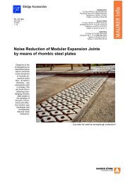
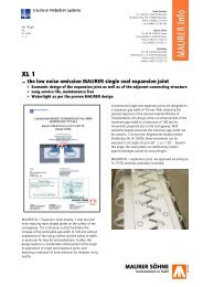
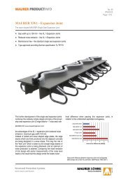
![[Brochure] MAURER Tuned Mass and Viscous Dampers](https://img.yumpu.com/46663805/1/184x260/brochure-maurer-tuned-mass-and-viscous-dampers.jpg?quality=85)
![[Broşürler] MAURER Tek Açıklıklı Genles¸me Derzleri](https://img.yumpu.com/41620362/1/184x260/brosurler-maurer-tek-acklkl-genlesme-derzleri.jpg?quality=85)