Principles and Theory of Radar Interferometry
Principles and Theory of Radar Interferometry
Principles and Theory of Radar Interferometry

Create successful ePaper yourself
Turn your PDF publications into a flip-book with our unique Google optimized e-Paper software.
<strong>Principles</strong> <strong>and</strong> <strong>Theory</strong> <strong>of</strong><br />
<strong>Radar</strong> <strong>Interferometry</strong> !<br />
Paul A Rosen!<br />
parosen@jpl.nasa.gov!<br />
Jet Propulsion Laboratory!<br />
May 17, 2011!
Outline <strong>of</strong> Tutorial!<br />
I. Quick Review <strong>of</strong> <strong>Radar</strong> Imaging Fundamentals<br />
A. Basic <strong>Principles</strong> <strong>of</strong> SAR<br />
B. Range <strong>and</strong> Azimuth Compression<br />
C. Doppler <strong>and</strong> its Implications<br />
D. Polarimetry <strong>and</strong> Image Characteristics<br />
II. Geometric Aspects <strong>of</strong> Interferometric Phase Measurement<br />
A."Interferometric Phase for Topographic Mapping <strong>and</strong> Deformation Mapping<br />
B."Sensitivity <strong>of</strong> Topographic <strong>and</strong> Deformation Phase Measurements<br />
III. Interferometric Correlation<br />
A. R<strong>and</strong>om <strong>and</strong> Deterministic Portions <strong>of</strong> the Interferometric Phase<br />
B. SNR <strong>and</strong> Interferometric Correlation<br />
C. Geometric Decorrelation <strong>and</strong> Range Spectral Shift<br />
D. Temporal Decorrelation<br />
E. Volumetric Decorrelation<br />
F. Other Error Sources<br />
IV. Interferometric Processing<br />
A. Processing Flow<br />
B. Interferogram Formation<br />
C. Image Co-registration<br />
D. Baseline Determination<br />
E. Phase Unwrapping<br />
F. Height Determination<br />
G. Deformation Signal Extraction
The <strong>Radar</strong> Concept!<br />
Transmitter/!<br />
Receiver!<br />
At light speed, c!<br />
Object scatters energy<br />
back to radar!<br />
!!!olleH<br />
Halo!!<br />
!!!olleH<br />
Hallo!!!<br />
•"<br />
•"<br />
Much like sound waves,<br />
radar waves carry<br />
information that echoes from<br />
distant objects!<br />
The time delay <strong>of</strong> the echo<br />
measures the distance to the<br />
object!<br />
•"<br />
The changes <strong>of</strong> the<br />
message in the echo<br />
determines the object<br />
characteristics !
Wave Properties <strong>of</strong> Light!<br />
•" <strong>Radar</strong> waves, like<br />
lightwaves, are<br />
electromagnetic energy<br />
that propagates!<br />
Energy propagates!<br />
4!
<strong>Radar</strong> <strong>and</strong> Light Waves!<br />
Millimeters to meters wavelength!<br />
Position z!<br />
•"<br />
•"<br />
•"<br />
<strong>Radar</strong>s operate at microwave frequencies,<br />
an invisible part <strong>of</strong> the electromagnetic<br />
spectrum!<br />
Microwaves have wavelengths in the<br />
millimeter to meter range!<br />
Like lasers, radars are coherent <strong>and</strong><br />
nearly a pure tone!<br />
The Electromagnetic Spectrum!<br />
Common <strong>Radar</strong> Frequency B<strong>and</strong>s!<br />
B<strong>and</strong>! X! C! S! L! P!<br />
Wavelength (cm)! 3! 6! 12! 24! 75!<br />
Frequency !<br />
(G-cycles/s)!<br />
10! 5! 2.5! 1.2! 0.4!<br />
tiny!<br />
100#s µm! mm#s to m#s!<br />
5!
Small antenna -!<br />
big beam!<br />
<strong>Radar</strong> on a Moving Platform!<br />
Big antenna!<br />
-small beam!<br />
•" Pulses are transmitted from<br />
the radar platform as it moves<br />
along its flight path!<br />
•" Each pulse has finite extent in<br />
time, illuminating a narrow strip<br />
<strong>of</strong> ground as it sweeps through<br />
the antenna beam!<br />
•" Some <strong>of</strong> the energy from the<br />
ground is scattered back to the<br />
radar instrument !<br />
Antenna Beamwidth!<br />
Footprint Size on Ground!
SAR Imaging Modes!<br />
–" Strip Mode: In strip mode the radar<br />
transmits a continuous sequence <strong>of</strong> pulses<br />
over the area to be imaged. Achievable<br />
azimuth resolution is the half the along-track<br />
antenna length.<br />
–" ScanSAR or Burst Mode: In ScanSAR or<br />
burst mode systems the radar transmits a<br />
sequence <strong>of</strong> pulses at the pulse repetition<br />
frequency (PRF) followed by a period <strong>of</strong> no<br />
transmission. This allows the radar to either<br />
scan to another elevation angle during the no<br />
transmission period thereby increasing swath<br />
width (ScanSAR mode) or remain silent<br />
thereby reducing the data rate. The increased<br />
swath width or data rate reduction are<br />
achieved at the expense <strong>of</strong> azimuth resolution<br />
<strong>and</strong> SNR.<br />
–" Spotlight Mode: In spotlight mode the radar<br />
transmits a sequence <strong>of</strong> pulses while directing<br />
the antenna to a specified point on the ground.<br />
This increases the amount <strong>of</strong> time an object is<br />
within the antenna beam <strong>and</strong> consequently the<br />
length <strong>of</strong> the synthetic aperture <strong>and</strong> thereby the<br />
azimuth resolution.<br />
7!
Point target!<br />
Matched Filtering <strong>of</strong> Received Echo!<br />
<strong>Radar</strong> Top View!<br />
•"<br />
•"<br />
Transmitted pulses are<br />
usually coded waveforms<br />
with significant b<strong>and</strong>width!<br />
Matched filtering allows<br />
recovery <strong>of</strong> fine resolution<br />
features with a low peakpower<br />
pulse train !
SAR Imaging Concept!<br />
Real Aperture<br />
Imaging<br />
Synthetic Aperture<br />
Imaging<br />
Cross-Track resolution<br />
achieved by short or coded<br />
pulses<br />
Along-Track resolution limited by beamwidth<br />
Along-Track resolution achieved by coherently<br />
combining echoes from multiple pulses along-track<br />
• Resolution proportional to antenna length<br />
• Independent <strong>of</strong> Range/Frequency<br />
Real Along Track Beam<br />
Synthesized Along Track Beam
Azimuth Resolution from Aperture<br />
Synthesis!<br />
•"<br />
•"<br />
•"<br />
•"<br />
The synthetic<br />
aperture X ill lengthens<br />
as R0 increases…!<br />
…which decreases<br />
the azimuth synthetic<br />
aperture#s angular<br />
beamwidth (!/X ill ) in<br />
proportion…!<br />
…but the spatial<br />
resolution on the<br />
ground (!R 0 /X ill = L/2)<br />
is constant !<br />
Aperture synthesis<br />
processing is very<br />
similar to matched<br />
filtering in range!
!" Strip-mode SAR!<br />
"" St<strong>and</strong>ard SAR mode!<br />
"" Send a pulse <strong>of</strong> energy; receive echo; repeat!<br />
"" One pulse transmit <strong>and</strong> receive at a time!<br />
"" Swath width limited by radar ambiguities!<br />
!" ScanSAR!<br />
"" Wider swath low resolution SAR mode!<br />
"" Execute sequence as follows:!<br />
"" Send a pulse <strong>of</strong> energy; receive echo; repeat 50-100 times!<br />
"" Repoint the beam across-track to position 2 electrically<br />
(almost instantaneous)!<br />
"" Send a pulse <strong>of</strong> energy; receive echo; repeat 50-100 times!<br />
"" Repoint the beam across-track to position 3 electrically<br />
(almost instantaneous)!<br />
"" Send a pulse <strong>of</strong> energy; receive echo; repeat 50-100 times!<br />
"" Again, one pulse transmit <strong>and</strong> receive at a time!<br />
"" ScanSAR trades resolution (in along-track dimension)<br />
for swath: low impact on data rate!<br />
"" Generally poorer ambiguity <strong>and</strong> radiometric<br />
performance than Strip SAR!<br />
StripSAR<br />
ScanSAR
ScanSAR Imaging <strong>and</strong> Burst Geometry!<br />
In ScanSAR the look angle<br />
for a burst <strong>of</strong> pulses<br />
changes for each dwell<br />
period!<br />
burst <strong>of</strong> pulses in<br />
alternating dwells…!<br />
…compared to a<br />
continuous strip <strong>of</strong><br />
pulses at fixed look angle!
Illustration <strong>of</strong> Burst Combination!<br />
Synthetic Aperture Length!<br />
Aperture Plane!<br />
Ground Plane!<br />
Images formed from each burst overlap in the ground plane.!<br />
Images are incoherently added (in power) to recover looks in processing.!
Strip versus ScanSAR images "<br />
(no radiometric calibration) !<br />
St<strong>and</strong>ard Strip Mode Amplitude (4 looks; then 4x4 more)!<br />
Burst Processed Amplitude (1/4 aperture; 2 looks; then 4x4 more)!<br />
Note Amplitude Scalloping!
The Doppler Shift!<br />
Phase <strong>of</strong> a wave is invariant with reference<br />
frame. As a result, the frequency in a moving<br />
frame must adjust to compensate for relative<br />
velocity
Doppler in SAR Imaging!<br />
Dropping the constant term<br />
t!
Range-Doppler Coordinates!
Doppler <strong>and</strong> Squint!<br />
18!
What <strong>Radar</strong> Can Tell Us!<br />
•"<br />
•"<br />
•"<br />
•"<br />
Transmitted radar signals have known characteristics!<br />
–" Amplitude!<br />
–" Polarization!<br />
–" Phase <strong>and</strong> Time Reference!<br />
–" Wavelength, or Frequency!<br />
A distant object that scatters the radar signal back toward the receiver<br />
alters the amplitude, polarization, <strong>and</strong> phase, differently for different<br />
wavelengths!<br />
Comparison <strong>of</strong> the received signal characteristics to the transmitted<br />
signal allows us to underst<strong>and</strong> the properties <strong>of</strong> the object.!<br />
This is the principle <strong>of</strong> active remote sensing.!
<strong>Radar</strong> Imaging Properties!<br />
• <strong>Radar</strong> images are distorted!<br />
relative to a planimetric view. !<br />
Slopes facing toward or away!<br />
from the radar appear foreshortened.!<br />
Steep slopes are collapsed into a !<br />
single range cell called layover <strong>and</strong>!<br />
areas occulted by other areas are !<br />
said to be shadowed.!<br />
Smooth<br />
Surface!<br />
Foreshortening!<br />
Rough<br />
Surfaces!<br />
Mountains!<br />
Forest!<br />
Urban!<br />
Area!<br />
• <strong>Radar</strong> is primarily sensitive to!<br />
the structure <strong>of</strong> objects being!<br />
imaged whereas optical images!<br />
are primarily sensitive to !<br />
chemistry.!<br />
• The scale <strong>of</strong> objects relative to!<br />
the radar wavelength determines!<br />
how smooth an object appears!<br />
to the radar <strong>and</strong> how bright or !<br />
dark it is in the imagery.!
Wavelength - A Measure <strong>of</strong> Surface Scale!<br />
Light interacts most<br />
strongly with objects on<br />
the size <strong>of</strong> the wavelength!<br />
Forest: Leaves reflect X-b<strong>and</strong><br />
wavelengths but not L-b<strong>and</strong> !<br />
L (24 cm)!<br />
C (6 cm)!<br />
X (3 cm)!<br />
Dry soils: Surface looks<br />
rough to X-b<strong>and</strong> but not L-<br />
b<strong>and</strong>!<br />
Ice: Surface <strong>and</strong> layering look<br />
rough to X-b<strong>and</strong> but not L-b<strong>and</strong>!
Polarization - A Measure <strong>of</strong> "<br />
Surface Orientations <strong>and</strong> Properties!<br />
Wave Polarization!<br />
Polarization Filters!<br />
Vertical polarization<br />
passes through<br />
horizontally arranged<br />
absorbers.!<br />
Horizontal polarization<br />
does not pass through<br />
horizontally arranged<br />
absorbers.!<br />
Mostly horizontal polarization<br />
is reflected from a flat surface.!<br />
Color figures from www.colorado.edu/physics/2000!
Death Valley!<br />
!""#$%&'(")(*(+,%%-'())(*(./0%1(
Speckle <strong>and</strong> Radiometric Accuracy !<br />
Natural “laser”<br />
speckle masks<br />
intrinsic radar<br />
backscatter which<br />
contains surface<br />
information,<br />
independent <strong>of</strong> SNR!!<br />
Spatial averaging<br />
(looks) reduces the<br />
speckle <strong>and</strong> draws<br />
out the natural<br />
backscatter<br />
reflectivity !
Spatial Averaging or Looks!<br />
DEM!<br />
Pixel!<br />
Product Estimation Cell!<br />
<strong>Radar</strong>!<br />
Pixel!
Phase - A Measure <strong>of</strong> "<br />
the Range <strong>and</strong> Surface Complexity!<br />
The phase <strong>of</strong> the radar signal is the number <strong>of</strong> cycles <strong>of</strong> oscillation<br />
that the wave executes between the radar <strong>and</strong> the surface <strong>and</strong> back<br />
again.!<br />
0! 1! 2!<br />
…!<br />
Number <strong>of</strong> cycles !<br />
(actually millions!)!<br />
The total phase is two-way range<br />
measured in wave cycles + r<strong>and</strong>om<br />
component from the surface !<br />
Collection <strong>of</strong> r<strong>and</strong>om path lengths<br />
jumbles the phase <strong>of</strong> the echo!<br />
<strong>Interferometry</strong> is used<br />
for measuring<br />
differential differences<br />
in phase!
What is <strong>Radar</strong> <strong>Interferometry</strong>?!<br />
•"<br />
<strong>Radar</strong> interferometry can be broadly defined by use <strong>of</strong> phase<br />
measurements to precisely measure the relative distance to an object when<br />
imaged by synthetic aperture radar from two or more observations<br />
separated either in time or space. !<br />
–" Interferometric phase is simply another means <strong>of</strong> measuring (relative)<br />
distance. !<br />
$%#<br />
2&#<br />
" = 2#<br />
!## "##<br />
$<br />
4&#<br />
1 !# 2 !#<br />
$%<br />
&<br />
!# "##<br />
$<br />
Radians per wavelength Number <strong>of</strong> wavelengths<br />
• Phase measurements in interferometric !<br />
systems can be made with degree level!<br />
accuracy, <strong>and</strong> with typical radar!<br />
wavelengths in 3-80 cm range!<br />
this corresponds to relative range !<br />
measurements having millimeter!<br />
accuracy. !
Interference Concept!<br />
•"<br />
Interference occurs when the phase <strong>of</strong> two different waves is<br />
not aligned. The observed intensity, I, is the time average <strong>of</strong> the<br />
sum <strong>of</strong> the wave fields!<br />
E(z,t)=E 0 cos(2&(f t - z / !))!<br />
Intermediate<br />
phase alignment!<br />
E 1!<br />
E 2!<br />
I!<br />
Phase aligned<br />
waves add<br />
constructively!<br />
Phase opposed waves<br />
add destructively!
•"<br />
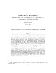
Young#s Interferometer!<br />
In Young#s experiment, a point source illuminates two separated<br />
vertical slits in an opaque screen. The slits are very narrow <strong>and</strong><br />
act as line sources. For this case, the pattern <strong>of</strong> intensity<br />
variations on the observing screen is bright/dark b<strong>and</strong>ing.!<br />
(Born <strong>and</strong> Wolf, 1980)!<br />
Observing Screen!<br />
Screen laid flat!
•"<br />
Young#s Interferometer Geometry!<br />
The brightness variations can be understood in terms <strong>of</strong> the<br />
relative phase <strong>of</strong> the interfering waves at the observing screen!<br />
•" The spacing <strong>of</strong> fringes is set by<br />
the slit separation!<br />
•" Phase = 2 & x d / a ! #<br />
•" x max = m a ! / d , m = 0, 1, 2 , ...!<br />
(Born <strong>and</strong> Wolf, 1980)!
<strong>Radar</strong> <strong>Interferometry</strong>!<br />
•"<br />
•"<br />
•"<br />
<strong>Radar</strong> <strong>Interferometry</strong> is a simple extension <strong>of</strong> the Young#s<br />
interferometry concept!<br />
<strong>Radar</strong> has a coherent source much like a laser!<br />
The two radar (SAR) antennas act as coherent point sources!<br />
•" Because the wavelengths are so<br />
long, the signal can easily be<br />
digitized <strong>and</strong> processed<br />
coherently, measuring the phase<br />
information directly.!<br />
•" When imaging a surface, the<br />
phase fronts from the two<br />
sources interfere. !<br />
•" The surface topography slices<br />
the interference pattern.!<br />
•" The measured phase differences record the topographic information.!
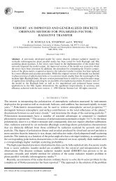
<strong>Radar</strong> <strong>Interferometry</strong> Example!<br />
St<strong>and</strong>ard <strong>Radar</strong> Image!<br />
Interference fringes follow!<br />
the topography!<br />
One cycle <strong>of</strong> color represents 1/2 wavelength <strong>of</strong> path difference!
Types <strong>of</strong> <strong>Radar</strong> <strong>Interferometry</strong>!<br />
•"<br />
Two main classes <strong>of</strong> interferometric radars are separated based on the<br />
geometric configuration <strong>of</strong> the baseline vector, i.e. the vector separating<br />
the antenna locations in the interferometric pair. These are:!<br />
–" Cross-Track interferometers used for topographic <strong>and</strong> surface deformation measurements<br />
whereby the antennas are nominally separated in the cross-track direction.!<br />
–" Along-Track interferometers used to measure radial velocity whereby the antennas are<br />
separated in the along-track direction.!<br />
Cross-Track Interferometer!<br />
Along-Track Interferometer!<br />
Radial!<br />
Motion!<br />
• Dual antenna single pass interferometers!<br />
• Single antenna repeat pass interferometers!<br />
==> Topography <strong>and</strong> Deformation!<br />
• Dual antenna single pass interferometer!<br />
• Along-track separation!<br />
==> Radial velocity!
<strong>Interferometry</strong> Applications!<br />
•"<br />
•"<br />
Mapping/Cartography!<br />
–" <strong>Radar</strong> <strong>Interferometry</strong> from airborne platforms is routinely used to produce<br />
topographic maps as digital elevation models (DEMs).!<br />
•"<br />
•"<br />
•"<br />
2-5 meter circular position accuracy!<br />
5-10 m post spacing <strong>and</strong> resolution!<br />
10 km by 80 km DEMs produced in 1 hr on mini-supercomputer!<br />
–" <strong>Radar</strong> imagery is automatically geocoded, becoming easily combined with<br />
other (multispectral) data sets.!<br />
–" Applications <strong>of</strong> topography enabled by interferometric rapid mapping!<br />
•"<br />
L<strong>and</strong> use management, classification, hazard assessment, intelligence, urban<br />
planning, short <strong>and</strong> long time scale geology, hydrology!<br />
Deformation Mapping <strong>and</strong> Change Detection!<br />
–" Repeat Pass <strong>Radar</strong> <strong>Interferometry</strong> from spaceborne platforms is routinely<br />
used to produce topographic change maps as digital displacement models<br />
(DDMs).!<br />
•"<br />
•"<br />
•"<br />
0.3-1 centimeter relative displacement accuracy!<br />
10-100 m post spacing <strong>and</strong> resolution!<br />
100 km by 100 km DDMs produced rapidly once data is available!<br />
–" Applications include!<br />
•"<br />
•"<br />
Earthquake <strong>and</strong> volcano monitoring <strong>and</strong> modeling, l<strong>and</strong>slides <strong>and</strong> subsidence!<br />
Glacier <strong>and</strong> ice sheet dynamics!<br />
•" Deforestation, change detection, disaster monitoring !
<strong>Interferometry</strong> for Topography!<br />
Measured phase difference:!<br />
!"!<br />
= " 2# $ %&<br />
Triangulation:!<br />
sin(! "#) = ($ +%$)2 " $ 2 " B 2<br />
2$B<br />
z = h ! "cos#<br />
B<br />
!<br />
A 1<br />
A 2<br />
! + "!<br />
!<br />
!<br />
h<br />
Critical Interferometer Knowledge:!<br />
- Baseline, (B,!),to mm#s!<br />
- System phase differences, to deg#s!<br />
z
Data Collection Options!<br />
For single pass interferometry (SPI) both antennas are located on the same<br />
platform. Two modes <strong>of</strong> data collection are common:!<br />
•" single-antenna-transmit mode - one antenna transmits <strong>and</strong> both receive!<br />
•" ping-pong mode - each antenna transmits <strong>and</strong> receives its own echoes<br />
effectively doubling the physical baseline.!<br />
Classic!<br />
!" !"<br />
! = 2" # ($ + $ ) % 2" 2 1<br />
# ($ + $ )<br />
1 1<br />
= 2" # ($ % $ )<br />
2 1<br />
! 1<br />
! 2<br />
"# = 2$p<br />
% &',<br />
p =1<br />
! 2<br />
Ping-Pong!<br />
! = 2" # ($ 2 + $ 2 ) % 2" # ($ 1 + $ 1 )<br />
= 4" # ($ 2 % $ 1 )<br />
! 1<br />
"# = 2$p<br />
% &',<br />
p = 2
•"<br />
Height Reconstruction!<br />
Interferometric height reconstruction is the determination <strong>of</strong> a target#s<br />
position vector from known platform ephemeris information, baseline<br />
information, <strong>and</strong> the interferometric phase. !<br />
!<br />
P = platform position vector!<br />
! =<br />
ˆ " =<br />
!<br />
T =<br />
range to target!<br />
unit vector pointing from platform to target!<br />
target location vector!<br />
BASIC EQUATION!<br />
!<br />
T = !<br />
P + ! ˆ "<br />
• <strong>Interferometry</strong> provides a means <strong>of</strong> determining !!<br />
ˆ .!
!<br />
P 1<br />
(#<br />
'#<br />
!<br />
b<br />
!<br />
"<br />
1<br />
!<br />
"<br />
!<br />
1 = 1<br />
Interferometric Geometry!<br />
!<br />
P<br />
2<br />
!<br />
"<br />
!<br />
b = P<br />
!<br />
2<br />
! P<br />
!<br />
1<br />
= !<br />
!<br />
" 2<br />
= !<br />
" 1<br />
! b<br />
!<br />
b = !<br />
b = !<br />
b , !<br />
b 1 2<br />
,!<br />
2<br />
!<br />
"<br />
!<br />
2 = 2<br />
" 1<br />
! !<br />
ˆ ! 1<br />
=<br />
!<br />
T<br />
" 2<br />
"<br />
! 1 "<br />
! 1<br />
=<br />
"<br />
! 1<br />
! 1<br />
!"!<br />
= 2" p<br />
#<br />
= 2! p<br />
"<br />
= 2! p<br />
"<br />
= 2! p<br />
"<br />
( $ 2<br />
% $ 1 ) = 2" p<br />
#<br />
%<br />
'<br />
&<br />
%<br />
'<br />
&<br />
%<br />
'<br />
&<br />
!<br />
" 2<br />
, ! 1<br />
" 2<br />
(<br />
2<br />
# $ 1 *<br />
)<br />
!<br />
" 1<br />
# b !<br />
, !<br />
" 1<br />
# b<br />
!<br />
2<br />
# 1 $ 2 !<br />
1<br />
2<br />
(<br />
# $ 1 *<br />
)<br />
( ) 1 2<br />
$ # 1<br />
" 1<br />
, b !<br />
+ b<br />
2<br />
= 2! p<br />
%<br />
" # %<br />
1<br />
1 $ 2 ! ˆ<br />
1<br />
, b<br />
"<br />
'<br />
'<br />
'<br />
& # 1<br />
&<br />
!<br />
" 2<br />
% !<br />
( " 1 )<br />
+<br />
% b (<br />
' *<br />
& )<br />
# 1<br />
• p equals 1 or 2 depending on system!<br />
2<br />
(<br />
*<br />
)<br />
(<br />
*<br />
)<br />
1<br />
2<br />
(<br />
$1*<br />
*<br />
)
2-D Height Reconstruction - Flat Earth!<br />
•"<br />
Before considering the general 3-D height reconstruction it is<br />
instructive to first solve the two dimensional problem.!<br />
" "<br />
Assume that b
2-D Height Reconstruction - Flat Earth II !<br />
!<br />
•" Let P = (y o , h) be the platform position vector, then !<br />
!<br />
P<br />
!<br />
T = P !<br />
+ ! " ˆ<br />
= (y o<br />
,h) + ! (sin(" ),# cos("))<br />
= (y o<br />
+ ! sin ("<br />
),h# ! cos(" ))<br />
h!<br />
(#<br />
y o!<br />
%#<br />
ˆ !<br />
!<br />
T<br />
• Solving for ( in terms <strong>of</strong> the !<br />
interferometric phase, !#, yields!<br />
( #$%& +<br />
" = sin #1 * - + .<br />
) 2'pb ,
Phase Gradient!<br />
• For a number <strong>of</strong> applications including flight planning <strong>and</strong> unwrapping<br />
studies it is desirable to be able to compute the interferometric phase<br />
gradient for an arbitrarily sloped surface, look geometry <strong>and</strong> baseline.!<br />
• The interferometric phase is well approximated for most applications by !<br />
" # $ 2%p !<br />
b , l ˆ<br />
(# ! !#)"<br />
!<br />
&<br />
where b is the baseline vector, l ˆ a unit vector pointing to the target <strong>and</strong> ! is<br />
the wavelength.!<br />
• The phase gradient is !<br />
& $# )<br />
(<br />
"# =<br />
$s<br />
+<br />
( $# +<br />
( +<br />
' $% *<br />
= , 2-p<br />
.<br />
&<br />
(<br />
(<br />
(<br />
(<br />
'<br />
!<br />
b , $ˆ l )<br />
+<br />
$s<br />
!<br />
b , $ˆ<br />
+<br />
l +<br />
+<br />
$% *<br />
where s is the along track coordinate <strong>and</strong> % is the range.!
Phase Gradient Observations!<br />
•"<br />
There in a change in phase with respect to range regardless <strong>of</strong><br />
whether the terrain is sloped in the range direction or not. The phase<br />
rate, or fringe rate, with respect to a flat surface is called the flat<br />
surface (or spherical earth) fringe frequency. !<br />
(# ! !#)"<br />
•"<br />
•"<br />
Note that the fringe rate depends on the local slope <strong>and</strong> the<br />
perpendicular baseline length.!<br />
The fringe rate in the azimuth or along track direction is zero unless<br />
there is an azimuth slope. It also depends on the magnitude <strong>of</strong> the<br />
local slope <strong>and</strong> the perpendicular baseline length!
Flattened Phase!<br />
• Often when looking at interferograms or prior to unwrapping it is desirable to<br />
remove the flat earth fringes so that the resulting fringes will follow the local<br />
topography. This process is call flattening <strong>and</strong> the resulting phase is called<br />
the flattened phase. !<br />
• The flattened phase is given by!<br />
!"<br />
where is the look vector to a point <strong>and</strong><br />
the flat surface at the same range.!<br />
is the corresponding look vector to<br />
• Making the usual 2 dimensional simplifications!<br />
!"
!<br />
( +#<br />
*(#<br />
%+*%#<br />
Flattened Phase II!<br />
!"<br />
%#<br />
%#<br />
( +#<br />
h T!<br />
From the figure we have !<br />
which gives!<br />
!"<br />
Thus the topographic portion <strong>of</strong> the interferometric phase is a function <strong>of</strong> the<br />
perpendicular baseline length. !
Sensitivity <strong>of</strong> Height with Respect to Phase!<br />
Sensitivity to Phase!<br />
" !<br />
T<br />
"# = $%&<br />
2'pbcos(( $ ))<br />
Ambiguity Height!<br />
* 0 -<br />
, /<br />
, cos( /<br />
+ , sin( ./<br />
h a = 2! "T z<br />
"# = $%&sin(' )<br />
pb cos(' $ ()<br />
p=1,2!<br />
(# ! !#)"<br />
! T<br />
• Observe that is parallel to ! ˆ ! v ˆ .!<br />
!"
•"<br />
3-D Height Reconstruction!<br />
The full three dimensional height reconstruction is based on the<br />
observation that the target location is the intersection locus <strong>of</strong><br />
three surfaces!<br />
!<br />
• range sphere! P ! T !<br />
= "<br />
!<br />
v , ˆ "<br />
• Doppler cone! f = 2 !<br />
• phase cone* !<br />
!"!<br />
= " 2# p<br />
$<br />
!<br />
b , ˆ "<br />
Doppler <strong>and</strong> phase!<br />
cones give two angles!<br />
defining spherical !<br />
coordinate system!<br />
• The cone angles are defined relative to the generating axes determined by!<br />
- velocity vector Doppler cone!<br />
- baseline vector phase cone!<br />
* Actually the phase surface is a hyperboloid, however for most applications!<br />
where the phase equation above is valid, the hyperboloid degenerates to a cone.!
Height Reconstruction Geometry!<br />
Range Sphere<br />
Doppler Cone<br />
Baseline<br />
Vector<br />
Aircraft<br />
Position<br />
Velocity<br />
Vector<br />
Phase Cone<br />
Scatterer is at intersection <strong>of</strong> Range<br />
Sphere, Doppler Cone <strong>and</strong> Phase<br />
Cone
Shuttle <strong>Radar</strong> !<br />
Topography Mission!<br />
This research was carried out at the Jet Propulsion Laboratory, California Institute <strong>of</strong> Technology, under a contract with the National Aeronautics <strong>and</strong> Space Administration!
Launch!<br />
Feb 11, 2000 - STS99!<br />
Mission Overview!<br />
225 km C-b<strong>and</strong> interferometric swaths<br />
map all l<strong>and</strong>mass between ±60° latitude<br />
at least twice!<br />
12 Tbytes data recorded on-board<br />
on 330 tape cassettes!<br />
Data returned with<br />
Shuttle to Ground Data<br />
Processing Facility!<br />
NIMA data validation, editing <strong>and</strong><br />
distribution to military users!<br />
EDC for public distribution!<br />
Digital elevation data delivered<br />
in 1°x1° mosaiced cells!<br />
Three year processing!
SRTM Patch Processing Example!
Need for Motion Compensation!<br />
Thruster !<br />
Firing!<br />
8 sec " 60 km!<br />
Plot <strong>of</strong> Baseline K Component!<br />
Plot <strong>of</strong> Roll Angle!<br />
• Motion compensation is required to account for boom dynamics as well as!<br />
shuttle attitude changes. Left uncompensated these motions would generate!<br />
hundreds <strong>of</strong> meters <strong>of</strong> height error. !
AODA!<br />
SRTM Hardware"<br />
Configuration!
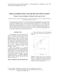
SRTM Resolution Improvement!<br />
GTOPO30 DEM!<br />
SRTM DEM with radar image overlay!<br />
Lake Balbina,<br />
Brazil!
SRTM Look at Central America!
SRTM Performance Summary!<br />
•"<br />
Based on over hundreds <strong>of</strong> millions <strong>of</strong> comparisons, SRTM has a absolute<br />
height accuracy <strong>of</strong> 9.0m or better over a 1 o x1 o cell, at the 90% confidence<br />
level.!
Data Collection Options!<br />
For single pass interferometry (SPI) both antennas are located on the same<br />
platform. Two modes <strong>of</strong> data collection are common:!<br />
•" single-antenna-transmit mode - one antenna transmits <strong>and</strong> both receive!<br />
•" ping-pong mode - each antenna transmits <strong>and</strong> receives its own echoes<br />
effectively doubling the physical baseline.!<br />
Classic!<br />
!" !"<br />
! = 2" # ($ + $ ) % 2" 2 1<br />
# ($ + $ )<br />
1 1<br />
= 2" # ($ % $ )<br />
2 1<br />
! 1<br />
! 2<br />
"# = 2$p<br />
% &',<br />
p =1<br />
! 2<br />
Ping-Pong!<br />
! = 2" # ($ 2 + $ 2 ) % 2" # ($ 1 + $ 1 )<br />
= 4" # ($ 2 % $ 1 )<br />
! 1<br />
"# = 2$p<br />
% &',<br />
p = 2
Data Collection Options II!<br />
Interferometric data can also be collected in the repeat pass mode (RPI). In<br />
this mode two spatially close radar observations <strong>of</strong> the same scene are<br />
made separated in time. The time interval may range from seconds to<br />
years. The two observations may be made different sensors provided they<br />
have nearly identical radar system parameters.!<br />
Second observation made at some later time.!<br />
!"<br />
! = 2" # ($ 2 + $ 2 ) % 2" # ($ 1 + $ 1 )<br />
! 1<br />
! 2<br />
= 4" # ($ 2 % $ 1 )<br />
"# = 2$p<br />
% &',<br />
p = 2
Differential <strong>Interferometry</strong>!<br />
When two observations are made from the same location in space<br />
but at different times, the interferometric phase is proportional to<br />
any change in the range <strong>of</strong> a surface feature directly.!<br />
!" = 4# $ (%(t 1 ) & %(t 2 )) = 4# $ !% change<br />
!(t 1<br />
)<br />
!(t 2<br />
)<br />
!" change
!<br />
P 1<br />
(#<br />
Differential Interferometric Phase!<br />
'#<br />
!<br />
b<br />
!<br />
"<br />
1<br />
!<br />
P<br />
2<br />
!<br />
"<br />
2<br />
!<br />
"<br />
!<br />
2 = 2<br />
!"! = 2" p<br />
#<br />
= 2! p<br />
"<br />
( $ 2<br />
% $ 1 ) = 2" p<br />
#<br />
%<br />
'<br />
&<br />
!<br />
" 2<br />
, ! 1<br />
" 2<br />
(<br />
2<br />
# $ 1 *<br />
)<br />
!<br />
" 2<br />
% !<br />
( " 1 )<br />
!<br />
"<br />
!<br />
1 = 1<br />
!"<br />
Assuming that !<br />
!<br />
b = !<br />
P 2<br />
" !<br />
P 1<br />
!<br />
T<br />
b = b !<br />
= b !<br />
, b<br />
!<br />
1<br />
2<br />
,!<br />
ˆ ! 1<br />
=<br />
"<br />
! 1 "<br />
! 1<br />
=<br />
"<br />
! 1<br />
! 1<br />
yields!<br />
!"
Differential <strong>Interferometry</strong> <strong>and</strong><br />
Topography!<br />
• Generally two observations are made from different locations in space<br />
<strong>and</strong> at different times, so the interferometric phase is proportional to<br />
topography <strong>and</strong> topographic change.!<br />
!"<br />
Topography!<br />
Term!<br />
Change!<br />
Term!<br />
!(t 1<br />
)<br />
!(t 2<br />
)<br />
!" change<br />
!"<br />
!"<br />
!"<br />
Note: Sensitivity <strong>of</strong> phase with respect to<br />
change is much greater than with respect<br />
to topographic relief!<br />
If topography is known, then<br />
second term can be eliminated to<br />
reveal surface change!
Extracting the Deformation Term - "<br />
Pre-Existing DEM!<br />
!"<br />
Phase Simulated from DEM!<br />
Using Unflattened Phases!<br />
"<br />
4# $% b 1<br />
& % topo ( )<br />
Using Flattened Phases!
A A<br />
2<br />
2<br />
'<br />
! !'<br />
! + "!<br />
A 1<br />
!<br />
z<br />
!<br />
Extracting the Deformation - "<br />
Three Passes!<br />
! + "!'<br />
!"<br />
!"<br />
Using Unflattened Phases!<br />
!"<br />
Change Pair!<br />
Topo Pair!<br />
!"<br />
!"<br />
!"<br />
Using Flattened Phases!
Differential <strong>Interferometry</strong><br />
Sensitivities!<br />
• The reason differential interferometry can detect millimeter level surface<br />
deformation is that the differential phase is much more sensitive to<br />
displacements than to topography.<br />
Topographic Sensitivity!<br />
(# ! !#)"<br />
Displacement Sensitivity!<br />
Topographic Sensitivity Term!<br />
Displacement Sensitivity Term!<br />
Since! ==>!<br />
Meter Scale Topography Measurement - Millimeter Scale Topographic Change
Strengths <strong>and</strong> Limitations!<br />
•" The major strengths for using radar differential<br />
interferometry are!<br />
–" Wide area coverage!<br />
–" Millimeter scale accuracy locally!<br />
–" Geophysically useful even without other data sets!<br />
–" Complementary to established geodetic <strong>and</strong> seismic tools<br />
(e.g. GPS <strong>and</strong> leveling)!<br />
•" Although there has been great success using radar<br />
differential interferometry for deformation<br />
measurement its application can be limited by!<br />
–" Temporal decorrelation <strong>of</strong> the surface!<br />
–" Other surface changes!<br />
–" Atmospheric <strong>and</strong> ionospheric effects!<br />
–" Poor DEM availability <strong>and</strong> Quality or lack <strong>of</strong> DEM pair!
Some Examples <strong>of</strong> Deformation!<br />
Hector Mine!<br />
Earthquake!<br />
Etna Volcano!
Example <strong>of</strong> SRTM DEM Improvement"<br />
Differential <strong>Interferometry</strong>!<br />
Using DTED+other DEM! Using SRTM DEM!<br />
Mount Etna inflation signature cleaned up considerably<br />
by using SRTM data to remove topographic<br />
signature.!
The time evolution <strong>of</strong><br />
ice stream flow<br />
variability is uniquely<br />
imaged by InSAR.<br />
Complete coverage by<br />
InSAR is needed to<br />
underst<strong>and</strong> flow<br />
dynamics <strong>of</strong> the<br />
potentially unstable<br />
marine ice sheet.<br />
Joughin et al , 1999!
Along Track <strong>Interferometry</strong> (ATI)!<br />
• By having antennas separated in !<br />
the along track direction interferometry !<br />
provides a very sensitive measure <strong>of</strong> the !<br />
line-<strong>of</strong>-sight velocity.!<br />
• Ocean currents <strong>and</strong> ship velocities can be!<br />
measured using along track interferometry.!<br />
! = 4" # $% = 4" #<br />
&%<br />
&t $t = 4" # V los<br />
D<br />
V spc
C-B<strong>and</strong> (AF/AA)!<br />
L-B<strong>and</strong> (AF/AA)!
Phase Measurements in<br />
<strong>Interferometry</strong>!<br />
!<br />
b<br />
"# topo<br />
= 2$p (<br />
% & ' & 1 2) = 2$p<br />
%<br />
( )<br />
"# meas<br />
= mod "# topo<br />
,2$<br />
!<br />
b • !<br />
l<br />
"# meas<br />
"# unwrap<br />
"# const Unwrapping is conducted<br />
"# unwrap<br />
(s,&) = "# topo<br />
(s,&) + "# const<br />
"# topo<br />
such that the unwrapped<br />
phase tracks the topographic<br />
phase except the entire<br />
image may be <strong>of</strong>f by a<br />
constant "# const
The ROI_PAC Algorithmic Flow!<br />
71!