VLIDORT User's Guide
VLIDORT User's Guide
VLIDORT User's Guide

You also want an ePaper? Increase the reach of your titles
YUMPU automatically turns print PDFs into web optimized ePapers that Google loves.
User’s <strong>Guide</strong><strong>VLIDORT</strong>Version 2.6Robert SpurrRT Solutions, Inc.9 Channing Street, Cambridge, MA 02138, USATel. +1 617 492 1183Fax: +1 617 492 1183 (request only)email: 0H0H0H0Hrtsolutions@verizon.net
ForewordThis is the User’s <strong>Guide</strong> to <strong>VLIDORT</strong> Version 2.6 issued in June 2012 in conjunction with therelease of the Version 2.6 FORTRAN 90 software package and accompanying license, and anaccompanying document containing a description of the test data sets in the installation package.The associated license closely follows the GNU public license formulation. Version 2.6 is the 6thofficial release. It follows the distribution of Version 1.0 in autumn 2004, Version 2.0 in January2006, Version 2.3 in October 2007, Version 2.4 in September 2009, and Version 2.5 inDecember 2010.3
Table of Contents1H1. Introduction to <strong>VLIDORT</strong> _____________________ 90H72H1.1. Historical and background overview ______________________________________________ 91H73H1.1.1. Polarization in radiative transfer ________________________________________________________ 92H74H1.1.2. Development of Linearized Vector RT models_____________________________________________ 93H85H1.2. Overview of the LIDORT and <strong>VLIDORT</strong> models ___________________________________ 94H86H1.2.1. LIDORT Scalar Model, Versions 1.0 to 3.3 _______________________________________________ 95H97H1.2.2. <strong>VLIDORT</strong> Development, Versions 1.0 to 2.4_____________________________________________ 96H108H1.2.3. LIDORT/<strong>VLIDORT</strong> Fortran 90 versions (3.5-3.6, 2.5-2.6) __________________________________ 97H119H1.3. LIDORT-RRS, 2-stream, Linearized Mie/Tmatrix codes ____________________________ 98H1210H1.4. Scope of document____________________________________________________________ 99H1211H2. Description of the <strong>VLIDORT</strong> model _________ 100H1532H3. The12H2.1. Theoretical Framework______________________________________________________ 101H1513H2.1.1. The vector RTE____________________________________________________________________ 102H1514H2.1.2. Azimuthal separation _______________________________________________________________ 103H1615H2.1.3. Boundary conditions ________________________________________________________________ 104H1816H2.1.4. Jacobian definitions_________________________________________________________________ 105H1917H2.1.5. Solution strategy ___________________________________________________________________ 106H1918H2.2. Discrete Ordinate Solutions and Linearizations _______________________________ 107H2019H2.2.1. Homogeneous RTE, Eigenproblem reduction_____________________________________________ 108H2020H2.2.2. Linearization of the eigenproblem _____________________________________________________ 109H2121H2.2.3. Particular Integral of the vector RTE, solar term __________________________________________ 110H2322H2.2.4. Particular Integral of the vector RTE, thermal emission_____________________________________ 111H2523H2.3. The post-processed solution ________________________________________________ 112H2624H2.3.1. Boundary value problem (BVP) and linearization _________________________________________ 113H2625H2.3.2. Source function integration ___________________________________________________________ 114H2826H2.4. Spherical and single-scatter corrections in LIDORT ___________________________ 115H3027H2.4.1. Pseudo-spherical approximation _______________________________________________________ 116H3028H2.4.2. Exact single scatter solutions _________________________________________________________ 117H3229H2.4.3. Sphericity along the line-of-sight ______________________________________________________ 118H3230H2.4.4. A more accurate outgoing sphericity correction ___________________________________________ 119H3331H2.5. Bulk (total column) atmospheric Jacobians. __________________________________ 120H37numerical <strong>VLIDORT</strong> model _____________ 121H3933H3.1. Preparation of inputs__________________________________________________________ 122H3934H3.1.1. Basic optical property inputs__________________________________________________________ 123H3935H3.1.2. Linearized optical property inputs______________________________________________________ 124H4036H3.1.3. Additional atmospheric inputs ________________________________________________________ 125H4137H3.1.4. Surface property inputs ______________________________________________________________ 126H4138H3.1.5. Thermal emission inputs _____________________________________________________________ 127H4239H3.2. Validation and benchmarking __________________________________________________ 128H4340H3.2.1. Checking against the scalar code ______________________________________________________ 129H4341H3.2.2. The Rayleigh slab problem ___________________________________________________________ 130H4342H3.2.3. Benchmarking for aerosol slab problems ________________________________________________ 131H4343H3.2.4. Weighting function verification _______________________________________________________ 132H4444H3.3. Performance considerations ____________________________________________________ 133H4545H3.3.1. The delta-M approximation___________________________________________________________ 134H455
52H4. The68H5. References__________________________________69H6. Appendices46H3.3.2. Multiple solar zenith angle facility _____________________________________________________ 135H4547H3.3.3. Eigensolver usage __________________________________________________________________ 136H4648H3.3.4. Solution saving ____________________________________________________________________ 137H4749H3.3.5. BVP telescoping ___________________________________________________________________ 138H4750H3.3.6. Convergence with exact single scatter and direct beam contributions __________________________ 139H4951H3.3.7 Enhanced efficiency for observational geometry output _____________________________________ 140H50<strong>VLIDORT</strong> 2.6 package___________________ 141H5353H4.1. Overview____________________________________________________________________ 142H5354H4.2. Source code Directories________________________________________________________ 143H5455H4.2.1. vlidort_def________________________________________________________________________ 144H5456H4.2.2. vlidort_main (Table 4.3) _____________________________________________________________ 145H5857H4.3. Calling <strong>VLIDORT</strong>, Configuration files, Makefiles, Installation _______________________ 146H6158H4.3.1. Calling environment – an example _____________________________________________________ 147H6159H4.3.2. Configuration file discussion _________________________________________________________ 148H6360H4.3.3. Makefile discussion_________________________________________________________________ 149H6361H4.3.4. Installation and testing ______________________________________________________________ 150H6862H4.3.5. Helpful Tips for input settings ________________________________________________________ 151H7363H4.4. Exception handling and utilities_________________________________________________ 152H7364H4.4.1. Exception handling _________________________________________________________________ 153H7365H4.4.2. Utilities __________________________________________________________________________ 154H7566H4.5. Copyright issues: GNU License _________________________________________________ 155H7567H4.6. Acknowledgments ____________________________________________________________ 156H76157H77___________________________________ 158H8370H6.1 Tables_______________________________________________________________________ 159H8371H6.1.1. <strong>VLIDORT</strong> I/O type structures_________________________________________________________ 160H8372H6.1.2. <strong>VLIDORT</strong> file-read character strings ___________________________________________________ 161H9573H6.2. Environment programs________________________________________________________ 162H9874H6.2.1. Programs for <strong>VLIDORT</strong> scalar tests____________________________________________________ 163H9875H6.2.2. Programs for <strong>VLIDORT</strong> vector tests __________________________________________________ 164H10376H6.3. BRDF Supplement___________________________________________________________ 165H10477H6.3.1. BRDFs as a sum of kernel functions___________________________________________________ 166H10478H6.3.2. Example calling sequence ___________________________________________________________ 167H10679H6.3.3. BRDF inputs and outputs ___________________________________________________________ 168H10780H6.3.4. Ocean glitter kernel function_________________________________________________________ 169H11281H6.3.5. Scalar land surface BRDF kernels_____________________________________________________ 170H11482H6.3.6. Polarized land surface BRDF kernels __________________________________________________ 171H11583H6.3.7. The direct beam correction for BRDFs _________________________________________________ 172H11584H6.4. SLEAVE Supplement ________________________________________________________ 173H11685H6.4.1. SLEAVE formulation ______________________________________________________________ 174H11686H6.4.2. Current development_______________________________________________________________ 175H11787H6.4.3. Example calling sequence ___________________________________________________________ 176H11888H6.4.4. SLEAVE inputs and outputs _________________________________________________________ 177H1196
1. Introduction to <strong>VLIDORT</strong>1.1. Historical and background overview1.1.1. Polarization in radiative transferThe modern treatment of the equations of radiative transfer for polarized light dates back to thepioneering work by Chandrasekhar in the 1940s [Chandrasekhar, 1960]. Using a formulation interms of the Stokes vector for polarized light, Chandrasekhar was able to solve completely thepolarization problem for an atmosphere with Rayleigh scattering, and benchmark calculationsfrom the 1950s are still appropriate today [Coulson et al., 1960]. Researchers started looking atthe scattering properties of polarized light by particles, and new more general formulations of thescattering matrices were developed independently by Hovenier [Hovenier, 1971] and Dave[Dave, 1970], and subsequently used in studies of polarization by Venus.With the advent of more powerful computers, a series of numerical RTMs were developedthrough the 1980s; many of these have become standards. In particular, the DISORT discreteordinate model developed by Stamnes and co-workers was released in 1988 for general use[Stamnes, et al., 1988]. Most RTMs today are either discrete ordinate codes or doubling-addingmethods, and vector models are no exception. In the 1980s, Siewert and colleagues made anumber of detailed mathematical examinations of the vector RT equations. The development ofthe scattering matrix in terms of generalized spherical functions was reformulated in aconvenient analytic manner [Siewert, 1981; Siewert, 1982; Vestrucci and Siewert, 1984], andmost models now follow this work (this includes <strong>VLIDORT</strong>). Siewert and co-workers thencarried out an examination of the discrete ordinate eigenspectrum for the vector equations, anddeveloped complete solutions for the slab problem using the spherical harmonics method[Garcia and Siewert, 1986] and the F N method [Garcia and Siewert, 1989]. These last twosolutions have generated benchmark results for the slab problem.Also in the 1980s, a group in the Netherlands carried out some parallel developments. Followingdetailed mathematical studies by Hovenier and others [Hovenier and van der Mee, 1983; deRooij and van der Stap, 1984], a general doubling-adding model was developed for atmosphericradiative transfer modeling [de Haan et al., 1987; Stammes et al., 1989]. This group was alsoable to provide benchmark results for the slab problem [Wauben and Hovenier, 1992]. Vectordiscrete ordinate models were developed in the 1990s, with VDISORT [Schultz et al., 2000] andits generalization [Schultz and Stamnes, 2000] to include the post processing function. In 1998,Siewert revisited the slab problem from a discrete ordinate viewpoint, and developed new andelegant solutions for the scalar [Siewert, 2000a] and vector [Siewert, 2000b] problems. One newingredient in these solutions was the use of Green’s functions to develop particular solutions forthe solar scattering term [Barichello et al., 2000]. For the vector problem, Siewert’s analysisshowed that complex eigensolutions for the homogeneous RT equations must be considered.Siewert also provided a new set of benchmark results [Siewert, 2000b]; this set and the resultsfrom [Garcia and Siewert, 1989] constitute our standards for slab-problem validation withaerosols.7
1.1.2. Development of Linearized Vector RT modelsIn the last fifteen years, there has been increasing recognition of the need for RT models togenerate fields of analytic radiance derivatives (Jacobians) with respect to atmospheric andsurface variables, in addition to simulated radiances. Such “linearized” models are extremelyuseful in classic inverse problem retrievals involving iterative least-squares minimization (withand without regularization). At each iteration step, the simulated radiation field is expanded in aTaylor series about the given state of the atmosphere-surface system. Only the linear term in thisexpansion is retained, and this requires partial derivatives of the simulated radiance with respectto atmospheric and surface parameters that make up the state vector of retrieval elements and thevector of assumed model parameters that are not retrieved but are sources of error in theretrieval.It is well known that the use of scalar radiative transfer (neglecting polarization) can lead toconsiderable errors for modeling backscatter spectra in the UV [Mishchenko et al., 1994; Lacis etal., 1998; Sromovsky, 2005]. Studies with atmospheric chemistry instruments such as GOME,SCIAMACHY and OMI have shown that the treatment of polarization is critical for thesuccessful retrieval of ozone profiles from UV backscatter [Schutgens and Stammes, 2003;Hasekamp et al., 2002]. The role of polarization has been investigated for retrieval scenariosinvolving important backscatter regions such as the oxygen A band [Stam et al., 1999, Jiang etal., 2003; Natraj et al., 2006]. It has also been demonstrated that the use of passive sensinginstruments with polarization capabilities can greatly enhance retrievals of aerosol information inthe atmosphere [Mishchenko and Travis, 1997; Deuze et al., 2000]; this is becoming a veryimportant issue as the scientific community tries to understand the effects of aerosol forcing[Heintzenberg et al., 1996; Mishchenko et al., 2004].Satellite instruments such as GOME-2 (launched in October 2006) [EPS/METOP, 1999] andOCO (Orbital Carbon Observatory) [Crisp et al., 2004] are polarizing spectrometers; vectorradiative transfer is an essential ingredient of the forward modeling component of their retrievalalgorithms. Vector RT modeling is slower than its scalar counterpart, and the treatment ofpolarization in forward modeling has often involved the creation of look-up tables of“polarization corrections” to total intensity. However, with the advent of new and plannedinstruments measuring polarization, there is a need for linearized vector models to deal directlywith retrieval issues.Historically, a number of linearized RT models were developed for the scalar RTE some yearsago [Rozanov et al., 1998; Landgraf et al., 2001; Spurr et al., 2001]. This includes the LIDORTlinearization (see below). Linearized vector radiative transfer models include the Gauss-Seidelcode [Landgraf et al, 2005 and reference therein], and the linearized <strong>VLIDORT</strong> model [Spurr,2006].1.2. Overview of the LIDORT and <strong>VLIDORT</strong> modelsIn this section we present a developmental review of the LIDORT and <strong>VLIDORT</strong> models. Insections 1.2.1 and 1.2.2 respectively, we summarize the earlier Fortran 77 versions up to the year2010 The most recent versions with re-organized codes and full Fortran 90 capability aresummarized separately in section 1.2.3.Table 1.1 gives a quick overview of the main developments and associated version numbers.8
Table 1.1 Major features of LIDORT and <strong>VLIDORT</strong>.FeatureLIDORTVersion<strong>VLIDORT</strong>VersionPseudo-spherical (solar beam attenuation) 2.1 1.0[Enhanced spherical (line-of-sight)] 2.2+ 2.1Green’s function treatment 2.3 n/a3-kernel BRDF + linearization 2.4 2.2Multiple solar zenith angles 3.0 2.2Solution saving, BVP telescoping 3.0 2.3Linearized thermal & surface emission 3.2 2.4Outgoing sphericity correction 3.2 2.3Total Column Jacobian facility 3.3 2.4Transmittance-only thermal mode 3.3 2.4Fortran 90 release 3.5 2.5BRDF supplement 3.5 2.5Structured I/O 3.5 2.5External SS 3.6 2.6BRDF upgrade and surface-leaving supplements 3.6 2.61.2.1. LIDORT Scalar Model, Versions 1.0 to 3.3The first version of LIDORT was developed in 1999 with the linearization of the completediscrete ordinate multiple-scattering RT solutions in a multi-layer atmosphere. Production ofweighting functions was restricted to TOA (top-of-atmosphere) upwelling output, with theatmospheric medium treated for solar beam propagation in a plane-parallel medium [Spurr et al.,2001]. Version 1.1 of LIDORT was able to generate atmospheric profile weighting functions andsurface albedo weighting functions (Lambertian). It also included an initial treatment ofatmospheric thermal emission source terms. The linearization was done by perturbation analysis.In 2000 and 2001, the second versions of LIDORT were developed, to include pseudo-sphericaltreatment of the solar beam attenuation in a curved atmosphere, and to extend the model for theoutput of weighting functions at arbitrary optical depths for downwelling and upwelling fields. Inthese models, the linearization formalism was cast in terms of analytic differentiation of thecomplete discrete ordinate solution. Green’s function methods were developed for solving theradiative transfer equation (RTE) for solar beam source terms. This work culminated in therelease of Versions 2.3S (radiance only) and 2.3E (with Jacobians) [Spurr, 2002; Van Oss &Spurr, 2002].In 2003, the LIDORT Version 2.2+ code was developed as a super-environment for LIDORT[Spurr, 2003]; this code has an exact treatment of single scattering for curved line-of-sight paths,thus giving LIDORT an “enhanced sphericity” treatment suitable for important satelliteapplications involving wide off-nadir viewing geometry (such as that for the Ozone MonitoringInstrument (OMI) which has a 2600 km swath). Version 2.4 developed in 2002-2003 provided anumber of extensions to deal in particular with bidirectionally reflecting surfaces [Spurr, 2004].BRDF functions were set up for a number of surface types using a linear combination of pre-setBRDF kernels (these are semi-empirical functions developed for particular types of surfaces),9
and a complete differentiation of the BRDF formulation was developed to generate Jacobianswith respect to surface variables such as the wind speed.Support for maintaining LIDORT Versions 1 and 2 came from a series of contracts over theperiod 1999-2004 which provided the sources of funding for R. Spurr while at SAO. Inrecognition of the need for a consistent set of supported RT codes for use at NASA-GSFC, acontract was set up between SSAI Inc. and RT Solutions Inc. for the developmental release ofLIDORT Versions 3.0 and beyond; all subsequent User <strong>Guide</strong>s were written under this aegis.From Version 3.0 onwards, all previous LIDORT codes are integrated. The last of the olderversions to be incorporated was Version 2.5; this had the specialist ability for fast generation oftotal column (as opposed to profile) Jacobians, and this capability was integrated into LIDORT3.3 in May 2007. New features for Versions 1.0 to 3.3 are (1) a Green’s function treatment of theRTE with atmospheric thermal emission; (2); a new outgoing sphericity correction that replacesthe old treatment of single scatter along the line-of-sight path; (3) the inclusion of a bulk property(total column) weighting function treatment. A number of other improvements were added,including a stand-alone facility for returning the single scatter radiance and Jacobians, anadditional scaling procedure for the single scatter RTE, and an internal adjustment to utilizegeometrical variables at any height in the atmosphere.1.2.2. <strong>VLIDORT</strong> Development, Versions 1.0 to 2.4In December 2003, a proposal was made to FMI for R. Spurr to develop the vector model<strong>VLIDORT</strong> as part of the O3SAF Visiting Scientist (VS) program in 2004. The first version of<strong>VLIDORT</strong> was completed in July 2004, given shakedown tests and validated against theCoulson/Dave/Sekera Rayleigh results [Coulson et al., 1960] and Siewert’s [Siewert, 2000b]benchmark results. The first application started in August 2004 with polarization sensitivitystudies on the UV product algorithm at FMI, and the Version 1.0 User’s guide appeared inSeptember 2004.In January 2005, a proposal was made and accepted for the continuation of <strong>VLIDORT</strong> studies aspart of the Ozone SAF Visiting Scientist Work in 2005. A number of <strong>VLIDORT</strong> improvements(refractive geometry, single scatter corrections, and performance enhancements) were made inspring 2005, and this was followed by an end-to-end linearization of the code, so that the newversion of <strong>VLIDORT</strong> now possessed a complete weighting-function capability. This December2005 version marked the completion of the initial <strong>VLIDORT</strong> development [Spurr, 2006] Afurther validation against the benchmark results of [Garcia and Siewert, 1989] was performed atthis time.Support for <strong>VLIDORT</strong> maintenance and development from 2006 has come from an RTSolutions’ contract with SSAI and NASA GSFC. The first new development for LIDORT and<strong>VLIDORT</strong> was the introduction of a new and more accurate single scatter scheme to allow forspherical geometry along the view path as well as the solar paths. The model has been usedextensively at NASA GSFC in OMI-related studies, and in spring 2007, it was carefullyvalidated against the older TOMRAD code at GSFC.For <strong>VLIDORT</strong> version 2.4R, the linearization facility was extended to include column or bulkproperty Jacobians, a facility that was introduced into the scalar LIDORT code in 2003. Inaddition to the new bulk Jacobian facility, version 2.4R also contains some new BRDFspecifications for polarized reflectance from land surfaces. Thermal emission was introducedinto this version of the code.10
In 2006, R. Spurr was invited to contribute a chapter on the LIDORT and <strong>VLIDORT</strong> models inthe book Light Scattering Reviews 3. This article [Spurr, 2008] contains a complete expositionof the theory behind the models, and the mathematical description in the present volume followsthis review article closely.1.2.3. LIDORT/<strong>VLIDORT</strong> Fortran 90 versions (3.5-3.6, 2.5-2.6)In recent years, many users have moved over to Fortran 90 programming for LIDORT and<strong>VLIDORT</strong> applications; among other reasons, this has necessitated a complete revision of thesoftware. In 2010, the LIDORT code was translated to Fortran 90 (Version 3.5), followed by<strong>VLIDORT</strong> in 2011 (Version 2.5). [Fortran 77 versions of these packages are still supported,though Version 2.6 of <strong>VLIDORT</strong> is only available in Fortran 90]. Although there has been littlenew physics introduced in these versions, the <strong>VLIDORT</strong> and LIDORT organization and codinghas been overhauled in order to bring the codes in line with modern computing standards. Animportant consideration has been the need for the codes to function in a parallel computingenvironment; this has meant that all COMMON blocks and associated "include" files have beenscrapped, to be replaced by explicit argument declarations for all inputs and outputs.With one exception (LIDORT has some capability to be used in parallel-computingenvironments), the LIDORT and <strong>VLIDORT</strong> packages have equivalent capability. Here, we listthe following attributes for <strong>VLIDORT</strong> Versions 2.5 and 2.6 (upgrades for the latter version arenoted separately):1. With the exception of the file <strong>VLIDORT</strong>.PARS, which contains only parameterstatements for symbolic array dimensioning, fixed indices and fixed numerical constants,all "include" files in previous Fortran 77 versions of <strong>VLIDORT</strong> have been removed.2. All variables are explicitly declared, and all input and output arguments clearly notated assuch. All routines have "implicit none" opening statements. All "GO TO" statementshave been removed.3. All Fortran 90 subroutine argument declarations have the intent(in), intent(out) andintent(inout) characterizations. Fortran 90 input and output arguments to the top-level<strong>VLIDORT</strong> calling routines are organized into a number of Type structures.4. A new exception handling system has been introduced. Formerly, input-check andcalculation errors were written to file as they occurred during model execution. This isnot convenient for applications where <strong>VLIDORT</strong> is embedded in a larger system; now,<strong>VLIDORT</strong> 2.5 will collect messages for output, and return error traces.5. The multi-kernel BRDF implementation has been moved out of the main <strong>VLIDORT</strong>model, and now exists as a supplement. <strong>VLIDORT</strong> will now ingest exact BRDFs (for usein single scatter corrections) and for the multiple scatter field, all Fourier components ofthe total BRDF (and any surface property derivatives) at discrete ordinate, solar andviewing angle stream directions. The BRDF supplement provides these inputs.6. The use of "normalized" weighting functions output has been discontinued for surfacelinearization. This makes it possible for example to define an albedo weighting functionin the limit of zero albedo.7. The new <strong>VLIDORT</strong> package has 2 master routines: one for intensity simulations alone,and a second (called the "LPCS" master) for calculations of atmospheric profile orcolumn weighting functions and surface property Jacobians.11
8. (Version 2.6). The BRDF supplement has been upgraded to include a facility forgenerating surface glitter BRDFs to include multiple reflections from wave facets.9. (Version 2.6). There is a new “surface-leaving” capability (e.g. for ocean water-leavingor fluorescence applications), and <strong>VLIDORT</strong> can ingest the correct functions formodeling this physical effect in the RTE. This additional “VSLEAVE” supplementprovides these functions.10. (Version 2.6). Single-scatter calculations are now optional; the model can ingest singlescatter fields from external sources.11. (Version 2.6). An observational geometry facility has been added to improvecomputational efficiency when doing satellite applications. The facility wasincorporated into <strong>VLIDORT</strong>’s main code as well as the BRDF and VSLEAVEsupplements.1.3. LIDORT-RRS, 2-stream, Linearized Mie/Tmatrix codesThe LIDORT linearization techniques have been applied to the CAO_DISORT coupledatmospheric-ocean code, and it is now possible to generate weighting function with respect tomarine constituents such as chlorophyll concentration and CDOM [Spurr, et al., 2007]. This hasopened the way for a new approach to simultaneous retrieval of atmospheric and ocean quantitiesfrom MODIS and related instruments. [Li et al., 2007].In 2002, a version of LIDORT with inelastic rotational Raman scattering (RRS) was developedfrom first principles, using an analytic solution of the discrete ordinate field in the presence ofadditional source terms due to RRS. This work was written up in [Spurr et al., 2008], andincludes Versions 1.5 through 2.1. The latter code has been used in a number of applicationsinvolving ozone profile and column retrievals from instruments such as GOME and OMI. In2009, a major new development for the LRRS code was the complete linearization of the entiremodel for profile, column and surface Jacobians. A separate User’s <strong>Guide</strong> is available forLIDORT-RRS.A dedicated 2-stream version of the multiple-scattering LIDORT code was written in 2010, foruse in low-stream interpolation and performance enhancement in hyperspectral retrievalapplications involving many radiative transfer techniques [Spurr and Natraj, 2011]. This 2S codeis entirely analytical, avoiding the use of LAPACK or other numerical schemes.More recently, some new work on the linearization of the T-matrix electromagnetic scatteringtheory has been published [Spurr et al., 2012] in connection with the development of <strong>VLIDORT</strong>basedpackages to retrieve aerosol microphysical properties. This work also includes a linearizedMie code formulation.1.4. Scope of documentA theoretical description of the model is given in chapters 2 and 3. Chapter 2 contains severalsections summarizing the essential mathematics and the solution methods of the discrete ordinatemultiple scattering radiative transfer formalism in a multi-layer medium. Some of the discreteordinate theory may be found in the literature, and many more details are found in the papers byR. Spurr. The linearization process and the derivation of Jacobians for atmospheric and surfacequantities are described in some detail, and there are treatments of exact single-scatter12
corrections, and sphericity corrections for the incoming solar beam and the outgoing line-ofsight.In Chapter 3, we go over the derivation of Inherent Optical Property (IOP) input preparation. Thederivation of the standard set of optical properties required for the computation of the Stokes 4-vector field is outlined, and derivations of linearized optical property inputs for the generation ofatmospheric Jacobians are discussed. Also in Chapter 3, we discuss benchmarking the modelagainst literature datasets, and there is another section on the use of performance enhancements,including the “solution-saving” and “BVP-telescoping” options; these are labor-saving devicesdesigned to eliminate unnecessary computation. We also review the Fourier convergence aspectspertaining to the exact treatments of single scattering and direct beam contributions, and the useof a multiple-SZA facility for look-up table generation.Chapter 4 describes the specifics of the <strong>VLIDORT</strong> 2.6 package. In section 4.1, we give anoverview of the package; section 4.2 has a description <strong>VLIDORT</strong>’s source code modules. Insection 4.3, we discuss the input configuration file, “makefile” production of executables, andinstallation of the code. In this regard, a number of tests have been written for this release of thecode, and proper installation of the package will result in the confirmation of the test data set thataccompanies the release. In section 4.4, we summarize the important new software standardsadopted for the code and describe exception handling. This version of <strong>VLIDORT</strong> is in the publicdomain; copyright and licensing issues are discussed in section 4.5. Chapter 4 concludes withsome acknowledgements in section 4.6. Chapter 5 contains references cited in the guide.Appendices for <strong>VLIDORT</strong> may be found in Chapter 6. Section 6.1 has important tablesdescribing <strong>VLIDORT</strong> input and output Fortran 90 type structure variables (both basic andlinearized) along with tables illuminating the association between these variables and the filereadinput strings found in <strong>VLIDORT</strong>’s input configuration file. Section 6.2 discusses theenvironment programs which serve as package installations tests as well as provide the user withexamples of how to incorporate <strong>VLIDORT</strong> into his or her desired applications. Lastly, section6.3 gives a complete description of the vector BRDF supplement: information on how theBRDFs are constructed, the inputs and outputs of the supplement software, and descriptions ofthe water and land surface BRDFs included in the package.13
2. Description of the <strong>VLIDORT</strong> model2.1. Theoretical Framework2.1.1. The vector RTEA first-principles derivation of the vector RTE has been given in the analysis of Mishchenko[Mishchenko, 2003]. The basic vector RTE is:∂μ I( x,μ,φ)= I(x,μ,φ)− J(x,μ,φ). (2.1)∂xHere, x is the optical thickness measured from the top of the layer, μ is the polar angle cosinemeasured from the upward vertical, and φ is the azimuth angle relative to some fixed direction.The 4-vector I is the diffuse field of Stokes components {I, Q, U, V} [Chandrasekhar, 1960],with I the total intensity, Q and U describing linearly polarized radiation, and V characterizingcircularly polarized radiation. Vector I is defined with respect to a reference plane (usually, thelocal meridian plane). The degree of polarization P of the radiation is:P +1 2 2 2= I− Q + U V . (2.2)The vector source term J(x,μ,φ) has the form:1 2πω(x)J ( x,μ,φ)= Π(x,μ,μ′, φ − φ′) I(x,μ′, φ′) dφ′dμ′+ Q(x,μ,φ)4π∫∫. (2.3)−10Here, ω is the single scattering albedo and Π the phase matrix for scattering. The first term in Eq.(2.3) represents multiple scattering contributions. For scattering of the attenuated solar beam, theinhomogeneous source term Q(x,μ,φ) is written:ω(x)Q ( x,μ,φ) = Π(x,μ, − μ0,φ− φ0) I0Ta exp[ −λx]. (2.4)4πHere, −μ 0 is the cosine of the solar zenith angle (with respect to the upward vertical); φ 0 is thesolar azimuth angle and I 0 the Stokes vector of the incoming solar beam before attenuation.The pseudo-spherical (P-S) beam attenuation in equation (2.4) is written T aexp[ − λx], where T a isthe transmittance to the top of the layer, and λ is a geometrical factor (the “average secant”). Inthe P-S formulation, all scattering takes place in a plane-parallel medium, but the solar beamattenuation is treated for a curved atmosphere. For plane-parallel attenuation, we have λ =−1/μ 0 .It has been shown that the P-S approximation is accurate for solar zenith angles up to 90°,provided the viewing path is not too far from the nadir [Dahlback and Stamnes, 1991]. Details onthe pseudo-spherical formulation are found in Section 2.4.1.In the model, we consider an atmosphere illuminated by natural (unpolarized) sunlight, so thatthe downwelling direct solar irradiance at TOA is given by Stokes vector I 0 = {I 0 ,0,0,0}. Weassume that the medium comprises a stratification of optically uniform layers; for each layer, thesingle scattering albedo ω and the phase matrix Π in Eq. (2.3) do not depend on the opticalthickness x, and we henceforth drop this dependence.15
Matrix Π relates scattering and incident Stokes vectors defined with respect to the meridianplane. The equivalent matrix for Stokes vectors with respect to the scattering plane is thescattering matrix F. In this work, we restrict ourselves to scattering for a medium that is“macroscopically isotropic and symmetric” [Mishchenko et al., 2000], with scattering forensembles of randomly oriented particles having at least one plane of symmetry. In this case, Fdepends only on the scattering angle Θ between scattered and incident beams. Matrix Π isrelated to F(Θ) through application of two rotation matrices L(π−σ 2 ) and L(−σ 1 ) (for definitionsof these matrices and the angles of rotation σ 1 and σ 2 , see [Mishchenko et al, 2000]):Π( μ,φ,μ′ , φ′) = L(π − σ 2) F(Θ ) L(−σ1); (2.5)22cos Θ = μ μ′+ 1 − μ 1 − μ ′ cos( φ − φ ′). (2.6)In our case, F(Θ) has the well-known form:⎛ a1(Θ)b1( Θ)0 0 ⎞⎜⎟⎜ b1( Θ)a2( Θ)0 0 ⎟F ( Θ)= ⎜ 0 0 ( ) ( ) ⎟ . (2.7)a3Θ b2Θ⎜⎟⎝ 0 0 − b2( Θ)a4( Θ)⎠The upper left entry in this matrix is the phase function and satisfies the normalization condition:12π∫0a1( Θ)sinΘdΘ= 1. (2.8)2.1.2. Azimuthal separationFor the special form of F in Eq. (2.7), the dependence on scattering angle allows us to developexpansions of the six independent scattering functions in terms of a set of generalized sphericallfunctions Pmn(cos Θ)[Mishchenko, et al., 2000]:LMa = ∑ P l1( )l 00(cos Θ)l=0aaΘ β ; (2.9)LMl2( Θ)+ a3(Θ)= ∑ (l+ ζl) P2,2(cosΘ)l=0α ; (2.10)LMl2( Θ)− a3( Θ)= ∑ (l− ζl) P2,−2(cos Θ)l=0LMa = ∑ P l4( )l 00(cos Θ)l=0α ; (2.11)Θ δ ; (2.12)LMb = ∑ P l1( )l 02(cosΘ)l=0Θ γ ; (2.13)LMb = −∑P l2( )l 02(cosΘ)l = 0Θ ε . (2.14)16
The six sets of “Greek constants” {α l , β l , γ l , δ l , ε l , ζ l } must be specified for each moment l inthese spherical-function expansions. The number of terms LM depends on the level of numericalaccuracy. Values {β l } are the phase function Legendre expansion coefficients as used in thescalar RTE. These “Greek constants” are commonly used to specify the polarized-light singlescatteringlaw, and there are a number of efficient analytical techniques for their computation,not only for spherical particles (see for example [de Rooij and van der Stap, 1984]) but also forrandomly oriented homogeneous and inhomogeneous non-spherical particles and aggregatedscatterers [Hovenier et al., 2004; Mackowski and Mishchenko, 1996; Mishchenko and Travis,1998].With this representation in Eqs. (2.9) to (2.14), one can then develop a Fourier decomposition ofΠ to separate the azimuthal dependence (cosine and sine series in the relative azimuth φ−φ 0 ).The same separation is applied to the Stokes vector itself. A convenient formalism for thisseparation was developed by Siewert and co-workers [Siewert, 1981; Siewert, 1982; Vestrucciand Siewert, 1984], and we summarize the results here for illumination by natural light. TheStokes vector Fourier decomposition is:LM1mmI x,μ,φ)= ∑ (2 − δm, 0)Φ ( φ − φ ) I ( x,μ); (2.15)2(0l = mmΦ ( φ)= diag{cosmφ,cosmφ,sinmφ,sinmφ}. (2.16)The phase matrix decomposition is:mm[ C ( μ,μ′)cosm(φ − φ′) + S ( μ,μ′)sin m(φ − )]LM1Π ( μ , φ,μ′ , φ′) = ∑(2− δ, 0)φ′m; (2.17)2l = mmmmC ( μ , μ′ ) = A ( μ,μ′) + DA ( μ,μ′) D ; (2.18)mmmS ( μ , μ′ ) = A ( μ,μ′) D − DA ( μ,μ′) ; (2.19)mALMmm( μ , μ′ ) = ∑ P ( μ)( μ′lBlPl) ; (2.20)l = mD = diag{ 1,1, −1,−1}. (2.21)This yields the following RTE for the Fourier component:dIμmLM( x,μ)m ω m+ I ( x,μ)= ∑ Pl( μ)BlPldx2∫Here, the source term is written:ωl = m1−1m17( μ′) Im( x,μ′) dμ′+ Qm( x,μ). (2.22)LMmmm−λxQ ( x,μ)= ∑ P ( lμ ) BlP( l−μ) 0I0Tae. (2.23)2 l=mThe phase matrix expansion is expressed through the two matrices:⎛ βlγl0 0 ⎞⎜⎟⎜ γlαl0 0 ⎟Bl= ⎜−⎟ ; (2.24)0 0 ςlεl⎜⎟⎝ 0 0 εlδl⎠
m⎛ P⎞l( μ)0 0 0⎜⎟mmm ⎜ 0 Rl( μ)− Tl( μ)0 ⎟Pl( μ)= ⎜mm⎟ . (2.25)⎜0 − Tl( μ)Rl( μ)0⎟m⎝ 0 0 0 Pl( μ)⎠The “Greek matrices” Β l for 0 ≤ l ≤ LM contain the sets of expansion coefficients that define themmscattering law. The Pl(μ)matrices contain entries of normalized Legendre functions Pl(μ)andfunctions R ml(μ)and mlTl(μ)which are related to Pmn(μ)(for details, see for example [Siewert,2000b]).2.1.3. Boundary conditionsDiscrete ordinate RT is pure scattering theory: in a multilayer medium, it is only necessary tospecify the layer total optical thickness values Δ n , the layer total single scatter albedo ω n , and thelayer 4 x 4 matrices Β nl of expansion coefficients (l being the moment number) for the totalscattering. To complete the calculation of the radiation field in a stratified multilayer medium,we have the following boundary conditions:(Ι) No diffuse downwelling radiation at TOA. Thus for the first layer we have:+In( 0, μ,φ)= 0 . (n = 1) (2.26)(ΙΙ) Continuity of the upwelling and downwelling radiation fields at intermediateboundaries. If N TOTAL is the number of layers in the medium, then:±( ) ±I n − 1Δ n −1 = I n(0) . (n = 2,…N TOTAL ) (2.27)(ΙΙΙ) A surface reflection condition relating the upwelling and downwelling radiation fieldsat the bottom of the atmosphere:−+I ( , μ , φ)= ( μ,φ;μ′, φ′) ( , μ′, φ′nΔnR InΔn) . (n = N TOTAL ) (2.28)Here, reflection matrix R relates incident and reflected directions.The convention adopted here is to use a “+” suffix for downwelling solutions, and a “−” suffixfor upwelling radiation. Conditions (I) and (II) are obeyed by all Fourier components in theazimuthal series. For condition (III), it is necessary to construct a Fourier decomposition of theBRDF operator R to separate the azimuth dependence; we return to this issue in section 2.5.4.The Lambertian case (isotropic reflectance) only applies for Fourier component m = 0 and Eq.(2.28) then becomes:1⎡⎤−I = ⎢ ( − ) + ∫ + ′ ′ ′n( Δn,μ)2δm, 0R0E1μ0I0Tn−1exp λnΔnIn( Δn,μ ) μ dμ⎥ . (2.29)⎣0⎦Here, R 0 is the Lambertian albedo, E 1 = diag{1,0,0,0}, and T n− exp( − λnΔn)1 is the wholeatmosphereslant path optical depth for the solar beam.18
2.1.4. Jacobian definitionsAtmospheric Jacobians (also known as weighting functions) are normalized analytic derivativesof the Stokes vector field with respect to any atmospheric property ξ n defined in layer n:∂I(x,μ,φ)Kξ( x,μ,φ)= ξ∂ξ. (2.30)The Fourier series azimuth dependence (c.f. Eq. (2.15)) is also valid:KLM1mmx,μ,φ)= ∑ (2 − δm, 0)C ( φ − φ ) Kξ( x,μ). (2.31)2ξ(0l=mWe use the linearization notation:y∂y= ξ ∂nLp(n)pξ , (2.32)pto indicate the normalized derivative of y n in layer n with respect to variable ξ p in layer p.As noted in section 2.1.3, for the radiation field, input optical properties are {Δ n , ω n , B nl } foreach layer n in a multilayer medium. For Jacobians, we require an additional set of linearizedoptical property inputs { Vn , U n, Z nl} defined with respect to variable ξ n in layer n for which werequire weighting functions. These are:Vn≡ Ln( Δn) ; Un≡ Ln( ωn) ; Znl≡ Ln( Bnl) . (2.33)Δ and itslinearizations{ Vn , U n, Z nl} for a typical atmospheric scenario with molecular and aerosolscattering. One can also define weighting functions with respect to basic optical propertiesthemselves: for example, if ξn= Δn, thenV n≡ Ln( Δn) = Δn .In section 3.2 we give an example of the construction of the input set {n, ωn,Bnl}For surface weighting functions, we need to know how the BRDF matrix operator R in Eq.(2.28) is parameterized. In <strong>VLIDORT</strong>, we have adopted a 3-kernel BRDF formulation of surfacereflectance similar to the scheme developed in [Spurr, 2003] for LIDORT. In section 2.3, weconfine our attention to the Lambertian case; BRDF implementation is discussed in section 6.3.2.1.5. Solution strategyThe solution strategy has two stages. First, for each layer, we establish discrete ordinate solutionsto the homogeneous RTE (in the absence of sources) and to the RTE with solar source term(section 2.2). Second, we complete the solution by application of boundary conditions and bysource function integration of the RTE in order to establish solutions away from discrete ordinatedirections (section 2.3). In section 2.4, we discuss the pseudo spherical approximation and exactsingle scattering calculations within <strong>VLIDORT</strong>, and section 2.5 deals with the surface boundarycondition for BRDFs.The complete vector RT solution for a plane-parallel slab was developed by Siewert [Siewert,2000b], and we follow some elements in this formulation. Our description also adheres closely tothe LIDORT treatment, especially concerning this particular integral solution, formulation of theboundary-value problem and linearization methodology.19
In the following sections, we suppress the Fourier index m unless noted explicitly, andwavelength dependence is implicit throughout. We sometimes suppress the layer index n in theinterests of clarity. For matrix notation, ordinary 4 x 1 vectors and 4 x 4 matrices are written inbold typeface, while 4N x 1 vectors and 4N x 4N matrices are written in bold typeface with atilde symbol (N is the number of discrete ordinate directions in the half-space).2.2. Discrete Ordinate Solutions and Linearizations2.2.1. Homogeneous RTE, Eigenproblem reductionFirst, we solve Eq. (2.22) without the solar source term. For each Fourier term m, the multiplescatter integral over the upper and lower polar direction half-spaces is approximated by a doubleGaussian quadrature scheme [Thomas and Stamnes, 1999], with stream directions {±μ i } andGauss-Legendre weights {w i } for i = 1,…N. The resulting vector RTE for Fourier component mis then:±LMNdIi( x)± ωnm+ m− m± μi± Ii( x)= ∑Pl( ± μi)Bl∑wj{ Ij( x)Pl( μj) + Ij( x)Pl( −μj)}dx2. (2.34)l = mj = 1±Eq. (2.34) is a set of 8N coupled first-order linear differential equations for Ii(x). As with thescalar case, these are solved by eigenvalue methods. We follow [Siewert, 2000b] for the mostpart. Solutions for these homogeneous equations are found with the ansatz:±Iα( x,± μi) = Wα( ± μi) exp[ −kαx]. (2.35)We define the (4N x 1) vector (superscript “T” denotes matrix transpose):~ ± TTTW [ ] Tα= Wα( ± μ1),Wα( ± μ2),...., Wα( ± μ N) . (2.36)~ ~ −Equations (2.34) are decoupled using = + ~ ~ ~ −XαWα+ Wαand = + ~YαWα− Wα(sum and differencevectors), and the order of the system can then be reduced from 8N to 4N. This gives aneigenproblem for the collection of separation constants {k α } and associated solution 4N-vectors{ X ~ α }, where α = 1,…4N. The eigenmatrix Γ ~ is constructed from optical property inputs ω andΒ l and products of the matrices Pml( μj) . The eigenproblem is:~ ⊥ ~ 2 ~ ⊥ ~ ~ 2 ~XαΓ = kαXα; ΓX α= kαXα; (2.37)~ ~ + ~ −Γ = S S ; (2.38)LM~ ± ⎡~ω ~± ~ T ~ ⎤ ~ −1S = ⎢E− ∑ Π(l,m)BlA Π ( l,m)Ω2⎥Μ; (2.39)⎣ l=m⎦mmm[ P ( μ ), P ( μ ),...., P ( μ ] T~Π ( l,m)= diag; (2.40)l1 l 2 l N)~M = diag[ μ1E,μ2E,...,μNE]; (2.41)~Ω = diag [ w1E,w2E,...,wNE]; (2.42)A±l−m= E ± ( −1)D . (2.43)20
Here, E is the 4 x 4 identity matrix, and E ~ the 4N x 4N identity matrix. The (⊥) superscriptindicates the conjugate transpose. The link between the eigenvector X ~α and the solution vectorsin Eq. (2.35) is through the auxiliary equations:~ ± ~ −1α = MW12⎡~1⎢E±⎣ kα~S+⎤ ~⎥X⎦α. (2.44)Eigenvalues occur in pairs { ± kα}. As noted by Siewert [Siewert, 2000b], both complex variableand real-variable eigensolutions may be present. Left and right eigenvectors share the samespectrum of eigenvalues. Solutions may be determined with the complex-variable eigensolverDGEEV from the LAPACK suite [Anderson, et al., 1995]. DGEEV returns eigenvalues plus leftandright-eigenvectors with unit modulus.In the scalar case, the formulation of the eigenproblem is simpler (see [Spurr, 2002] forexample). The eigenmatrix is symmetric and all eigensolutions are real-valued. In this case, theeigensolver module ASYMTX [Stamnes et al., 1988] is used. ASYMTX is a modification of theLAPACK routine for real roots; it delivers only the right eigenvectors. For the vector case, thereare circumstances (pure Rayleigh scattering for example) where complex eigensolutions areabsent, and one may then use the faster ASYMTX routine. We return to this point in section3.4.3.The complete homogeneous solution in one layer is a linear combination of all positive andnegative eigensolutions:~ ~I ; (2.45)~4N~ +~ −∑{ LαWαexp[ −kαx]+ MαWαexp[ −kα( Δ x)]}++( x)= D−α = 1~4N~ −~ +∑{ LαWαexp[ −kαx]+ MαWαexp[ −kα( Δ − x)]}−I−( x)= D. (2.46)α = 1~ −~ + ~Here, D = diag{D,D,...,D}and D = E. The use of optical thickness Δ − x in the secondexponential ensures that solutions remain bounded [Stamnes and Conklin, 1984]. The quantities{ Lα, M α} are the constants of integration, and must be determined by the boundary conditions.In equations (2.45) and (2.46), some eigensolutions will be complex, some real. It is understoodthat when we use these expressions in the boundary value problem (section 2.3.1), we computethe real parts of any contributions to the Stokes vectors resulting from complex eigensolutions.~Thus if { k +α, W α} is a complex solution with (complex) integration constant Lα , we require:~ − −k~~α x− −kαx− −kαxRe[ LαWαe ] = Re[ Lα]Re[ Wαe ] − Im[ Lα]Im[ Wαe ]. (2.47)From a bookkeeping standpoint, one must keep count of the number of real and complexsolutions, and treat them separately in the numerical implementation. In the interests of clarity,we have not made an explicit separation of complex variables, and it will be clear from thecontext whether real or complex variables are under consideration.2.2.2. Linearization of the eigenproblemWe require derivatives of the above eigenvectors and separation constants with respect to someatmospheric variable ξ in layer n. From (2.38) and (2.39), the eigenmatrix Γ ~ is a linear function21
of the single scatter albedo ω and the matrix of expansion coefficients Β l , and its (real-variable)~linearization L (Γ)is easy to establish from chain-rule differentiation:~ ~ + ~ − ~ + ~ −L ( Γ)= L(S ) S + S L(S ) ; (2.48)L(⎡L(ω)LM~ ± ⎧ ~~ ⎫ ± ~ T ~ ~ −1S ) = ⎢∑⎨Π(l,m)Bl+ Π(l,m)L(Bl) ⎬AΠ ( l,m)Ω= 22⎥Μl m⎣⎩ω⎭⎤⎦. (2.49)In Eq. (2.49), L (ω)= U and L (Bl) = Zlare the linearized optical property inputs (Eq. (2.33)).Next, we differentiate both the left and right eigensystems (2.37) to find:~ ⊥ ~ ~ ⊥ ~~ ⊥ 2 ~ ⊥L(Xα) Γ + XαL(Γ)= 2k αL(kα) Xα+ kαL(Xα) ; (2.50)~ ~ ~ ~~ 2 ~ΓL(Xα) + L(Γ)Xα= 2k αL(kα) Xα+ kαL(Xα) . (2.51)⊥We form a dot product by pre-multiplying (2.51) with the transpose vector X ~ α , rearranging toget:~ ⊥ ~ ~ ⊥ ~ ~ 2 ~ ⊥ ~ ~ ⊥ ~ ~2k αL(kα)〈Xα, Xα〉 − 〈 Xα, L(Γ)Xα〉 = kα〈 Xα, L(Xα)〉− 〈 Xα, ΓL(Xα)〉. (2.52)From the definitions in Eq. (2.37), we have:~ ⊥ ~ ~ ~ ⊥ ~ ~2 ~ ⊥ ~〈 Xα, ΓL(Xα)〉= 〈 XαΓ,L(Xα)〉= kα〈 Xα, L(Xα)〉, (2.53)and hence the right hand side of (2.52) is identically zero. We thus have:~ ⊥ ~〈 Xα, L(Γ~ ) Xα〉L ( kα) = ~ ⊥ ~ . (2.54)2k〈 X , X 〉αααNext, we substitute Eq. (2.54) in (2.52) to obtain the following 4N x 4N linear algebra problemfor each eigensolution linearization:~ ~ ~ΗαL ( Xα) = Cα; (2.55)~ ~ 2~Hα = Γ − k αE ; (2.56)~~ ~Cα= 2k αL(kα) Xα− L(Γ~ ) Xα. (2.57)Implementation of Eq. (2.55) “as is” is not possible due to the degeneracy of the eigenproblem,and we need additional constraints to find the unique solution for L ( X~α) . The treatment for realand complex solutions is different.~ ~Real solutions. The unit-modulus eigenvector normalization can be expressed as 〈 X , X 〉 α α= 1 indot-product notation. Linearizing, this yields one equation:~ ~ ~ ~L ( Xα) Xα+ XαL(Xα) = 0. (2.58)The solution procedure uses 4N −1 equations from (2.55), along with Eq. (2.58) to form aslightly modified linear system of rank 4N. This system is then solved by standard means usingthe DGETRF and DGETRS LU-decomposition routines from the LAPACK suite.22
This procedure was not used in the scalar LIDORT code [Spurr et al., 2001; Spurr, 2002]. Thisis because ASYMTX has no adjoint solution, so there is no determination of L ( k α) as in Eq.(2.54). Instead, LIDORT uses the complete set (2.55) in addition to the constraint (2.58) to forma system of rank N + 1 for the unknowns L( k α) and L ( X~α) .Complex solutions. In this case, Eq. (2.55) is a complex-variable system for both the real andimaginary parts of the linearized eigenvectors. There are 8N equations in all, but now we requiretwo constraint conditions to remove the eigenproblem arbitrariness. The first is Eq. (2.58). Thesecond condition is imposed by the following DGEEV normalization: for that element of aneigenvector with the largest real value, the corresponding imaginary part is always set to zero.Thus for an eigenvector X ~ , if element Re[X J ] = max{Re[X j ]} for j = 1,… 4N, then Im[X J ] = 0. Inthis case, it is also true that L(Im[X J ]) = 0. This is the second condition.The solution procedure is then (1) in Eq. (2.55) to strike out the row and column J in matrix Η ~αfor which the quantity Im[X J ] is zero, and strike out the corresponding row in the right-handvector C ~ α ; and (2) in the resulting 8N−1 system, replace one of the rows with the normalizationconstraint Eq. (2.58). L ( X~α) is then the solution of the resulting linear system.We have gone into detail here, as the above procedure for eigensolution differentiation is themost crucial step in the linearization process, and there are several points of departure from theequivalent procedure in the scalar case. Having derived the linearizations L( k α) and L ( X~α) , we~ ±complete this section by differentiating the auxiliary result in Eq. (2.44) to establish L ( W α) :~L(W±α1 ~) = M2−1⎡ L(kα) ~ + 1 ~ +⎤ ~ 1 ~ −1⎡~1 ~ +⎤ ~⎢m S ± L(S ) X( )2⎥ α + M ⎢E± S ⎥LXα. (2.59)⎣ kαkα⎦ 2 ⎣ kα⎦Finally, we have linearizations of the transmittance derivatives in Eqs. (2.45) and (2.46):L (exp[ −kαx])= −x{ L(kα) + kαL(x)} exp[ −kαx]. (2.60)Here, x and Δ n are proportional for an optically uniform layer, so thatx xLξ( x)= Lξ( Δn)= VξΔ Δ. (2.61)nn2.2.3. Particular Integral of the vector RTE, solar termSolving the RTE by substitutionIn the treatment of the particular integral solutions of the vector RTE, we use a more traditionalsubstitution method rather than the Green’s function formalism of Siewert [Siewert, 2000b]. Thisis mainly for reasons of clarity and ease of exposition. Referring to Eq. (2.23), inhomogeneoussource terms in the discrete ordinate directions are:Lm ω mmQn( x,± μi) = ∑ Pl( ± μi) BnlPl( −μ0)I0Tn−1exp( −λnx). (2.62)2l=m23
Here T n−1 is the solar beam transmittance to the top of layer n, and in the pseudo-sphericalapproximation, λ n is the average secant (section 2.4.1). Particular solutions may be found bysubstitution:±I ( x,± μi)= Zn(± μi)Tn−1 exp[ −λnx], (2.63)and by analogy with the homogeneous case, we define the 4N x 1 vectors:TTT[ Z ( ± μ ), Z ( ± μ ),...., Z ( ± μ )] T~ ±Z =. (2.64)nn1n2nN~ ± ~ + ~ −We decouple the resulting equations by using sum and difference vectorsGn= Zn± Zn, andreduce the order from 8N to 4N (see [Van Oss and Spurr, 2002] for the scalar case). We obtainthe following 4N x 4N linear-algebra problem:~ ( 2) ~ + ~ (2)AnGn= Cn; (2.65)~ ( 2) 2 ~ ~A = λ E − Γ ;~ (2)C~ − ~ += S Q~ −+ λ Q~ −Μ ; (2.66)nnnn[ ]1LM~ ± ~± ~ T ~ −1Qn= ∑ Π0(l,m)BlAΠ ( l,m)Μl = mnnnnω ; (2.67)~mHere, Π0( l,m)is defined as in Eq. (40) but for matrices Pl( −μ0) . This system (2.65-2.67) hassome similarities to the eigensolution linearization in equations (2.55-2.58). It is also solvedusing the LU-decomposition modules DGETRF and DGETRS from LAPACK; the formal~ ~ 2)1(2)solution is [ ( ~Gn n] + −= A Cn . The particular integral is completed through the auxiliaryequations:1⎡⎤ ~~ ± ~ −1~+ +Zn= M ⎢E± Sn⎥Gn2 λn⎣1~⎦. (2.68)We note that the particular solution consists only of real variables.Linearizing the particular solutionFor the linearization, the most important point is the presence of cross-derivatives: the particularsolution is differentiable with respect to atmospheric variables ξ p in all layers p ≥ n. The solarbeam has passed through layer p ≥ n before scattering, so transmittance factor T n−1 depends onvariables in layers p > n and the average secant λ n (in the pseudo-spherical approximation) on±variables ξ p for p ≥ n In addition, the solution vectors Z ~n depend on λ n , so their linearizationscontain cross-derivatives.Linearization of the pseudo-spherical approximation is treated in Appendix A, and this fixes thequantities L p (T n−1 ) and L p (λ n ) ∀ p ≥ n. For the plane-parallel case, Lp( λ n) ≡ 0 since λn= −1/μ0(constant). In addition, the eigenmatrix Γ ~n is constructed from optical properties only defined in~layer n, so that Lp( Γ n) = 0 ∀ p ≠ n. Differentiation of Eqs. (2.65-2.67) yields a related linearproblem:~ (2) ~ + ~ (3) ~ (2) ~ (2)~ +AnLp( Gn) ≡ Cnp= Lp( Cn) − Lp( An) Gn ; (2.69)24
~L ( Ap~L ( Cp~(2)n(2)n) = −δL) = δnppn⎡⎢L⎣np~( Γ ) + 2λL~( S−nn~) Q+nn−np~+ S L~( λ ) E;nn~( Q+n) +1Lλnn~( Q−n⎤ Lp( λn) ~) ⎥ − Q2⎦ λn~~± ~ T ~ −1[ U Π ( l,m)B Π ( l,m)Z ] A Π ( l,m)−n; (2.70)LM±Ln( Qn) = ∑ n 0l+ ωn 0nlΜ . (2.71)l=m~In Eq. (2.70), the quantity L ( − nSn) comes from (2.49). Equation (2.69) has the same matrix~A (2)n as in Eq. (2.65), but with a different source vector on the right hand side. The solution is~ (2)then found by back-substitution, given that the inverse of the matrix An has already beenestablished for the original solution G ~ + ~ + ~ 2)1(3)n . Thus [ (− ~Lp( Gn) = An] Cnp. Linearization of theparticular integral is then completed through differentiation of the auxiliary equations (2.68):~1~⎡~⎤~ + ~ + ~ +[ λ δ L ( S ) − L ( λ ) S )] G±−1++−1Lp( Zn) = M ⎢E± Sn ⎥Lp( Gn) m M2 n pn p n p n n n . (2.72)2 λn2λn⎣1~⎦~1~This completes the RTE solution determination and the corresponding linearizations with respectto atmospheric variables.2.2.4. Particular Integral of the vector RTE, thermal emissionIn this section, we determine solution of the RTE in the presence of atmospheric thermalemission sources. This formalism is based on the substitution approach used in the originalLIDORT work [Spurr et al., 2001] and in the DISORT formalism [Stamnes et al., 1988], butwith a newly worked out reduction in the order of the corresponding linear algebra system. Wealso present a linearization of this solution with respect to the atmospheric profile variables.[Linearization with respect to the Black Body temperatures themselves is another story, and iscurrently being worked on].The source is now isotropic thermal emission, with amplitude is equal to qn( x)= (1 − ωn) ηn( x),where ηn(x)is the Black Body Planck function expressed as a function of vertical opticalthickness within layer n. The phase function for scattering is 1, and the thermal term is onlypresent for the azimuthal series term m = 0. There is no polarization, so we deal with only the(1,1) component of the phase matrix.In order to obtain solutions, the Planck function is expressed as a polynomial in x across thelayer. For convenience, we assume the linear form ηn( x)= an+ bnx . Then, the thermal emissionis piecewise continuous through the whole atmosphere and may be completely specified byvalues of the Planck function B n at the layer boundaries. We find that a n= B n− 1, andbnΔn= Bn− Bn−1, where Δ n is the whole-layer optical thickness. We expect the discrete ordinatefield to show the same dependency on optical thickness x, so we look for solutions of the form± ~ 1) ± (2) ±= ( ~In( x)Tn+ xTn. We decouple the resulting equations by using sum and difference vectors:~ ( 1) ± 1~ (1) ~ (1) ~ (2) ± 1~ (2)Tn=2( Hn± Jn); Tn=2Hn; this reduces the order from 2N to N. Substitution in theRTE, and equating powers of x yields the following solution using linear algebra:25
~ + ~ ~ (1)~ ~ + ~ ~ (2)~ ~ − ~ 1) (2)( S M) H = (1 − ) E; ( S M) H = (1 − ) E ; ( ) ( ~S J = −Hn nanωnn nbnωnnnn. (2.73)Here, the solution vectors are for the discrete ordinates, and the S ~ ± nmatrices are given byEquation (2.39) but with entries restricted to the (1,1) component of the 4 x 4 polarization~matrices. Also, in this result, M = diag[μ , μ , Kμ] , and E ~ the N x N identity matrix.1 2 NLinearization of these solutions is straightforward. The Planck functions depend only on theBlackbody emission temperature, and for now we will leave out consideration of thetemperature-field weighting function. In terms of our linearization notation,∂an∂bnBn− Bn−1vnbnLn( an) ≡ ξn= 0; Ln( bn) ≡ ξn= −( ) vn= − . (2.74)2∂ξn∂ξn ΔΔnnThus, linearizing the three systems in Eq. (2.73), we find~ + ~ ~ (1) ~ ~ + ~ ~ (1)( SnM) Ln[ Hn] = −anunE− ( LnSnM)Hn~ + ~ ~ (2) ~~ ~ + ~ ~ (2)( SnM) Ln[ Hn] = −bnunE+ Ln[ bn]( 1−ωn) E − ( LnSnM)Hn. (2.75)~ − ~ (1) ~ (2) ~ − ~ (1S L J = −LH − L S J( ) [ ] [ ] ( ))nnnnnnnn~ ± ~ ~The RTE also admits solutions in the absence of scattering. In this case, ωn= 0 , SnM = E, and~ ~the solutions are trivial: H ( 1)~ ~n= anE, H ( 2)~ ( 1) ~ −1~ (2)n= bnE, and Jn= −MH n. The linearization (2.74)still applies, with the linearized solutions in Eq. (2.75) simplified accordingly. This “thermaltransmittance” solution has been included in the model in order that fast solutions to the RTEmay be obtained in the infrared and beyond.2.3. The post-processed solution2.3.1. Boundary value problem (BVP) and linearizationFrom Section 2.1.3, the complete Stokes vector discrete ordinate solutions in layer n may bewritten:4N~ ± ~ ± ~ ± −nxn nxx[ ] k ~αm − k α( Δ − ) ~ ± −λnIn( x)= D ∑ LnαWnαe + MnαWnαe + ZnTn−1e. (2.76)α = 1Quantities Lnαand Mnαare constants of integration for the homogeneous solutions, and theyare determined by the imposition of three boundary conditions as noted in section 2.1.3. For~ +boundary condition (I), we have In(0) = 0 for n = 1, which yields (T 0 = 1):N~ +D ∑4α = 1~ + ~ − ~ +[ L W + M W ] = −Znα nαnαnαΚnαn . (2.77)For boundary condition (II), the continuity at layer boundaries, we have:~D±4N~ ±~ m ~ ± ~ m∑ [{ LnαWnαΚnα+ MnαWnα} − { LpαWpα+ MpαWpαΚpα}]α = 1~ ~Z Λ . (2.78)±±= −nTn−1n+ ZpTp−126
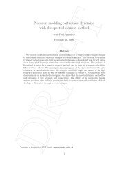
In Eq. (2.78), p = n + 1. For surface condition (III), staying for convenience with the Lambertiancondition in Eq. (29), we find (for layer n = N TOTAL ):α = 1~ − ~ +~ − ~[ L V + M V ] = T [ − U 2Rμ E I ]4N~ −D ∑ Λnα αΚnαnαα n−1n+0 0 1 0 . (2.79)Here we have defined the following auxiliary quantities:~ ± ~ ± ~ T ~ ~ ~ m ~Vα= Wnα− 2R0E1MΩWnαE1; (n = N TOTAL ) (2.80)~ − ~ − ~ T ~ ~ ~ + ~U = Zn− 2R 0E1MΩZnE1; (n = N TOTAL ) (2.81)~E = diag{E , E ,... }; (2.82)1 1 1E1− k nα nΚneΔα= ;Λn−λnΔn= e . (n = 1,…N TOTAL ) (2.83)Application of Eqs. (2.77-2.79) yields a large, sparse banded linear system with rank 8N xN TOTAL . This system consists only of real variables, and may be written in the symbolic form:Φ ∗ Ξ = Ψ . (2.84)Here Ψ is constructed from the right hand side variables in Eqs. (2.77-2.79) andΦ is constructed~ ± ±from suitable combinations of Vα, W~nα and Κnα. For a visualization of the BVP in the scalarcase, see [Spurr et al., 2001]. The vector Ξ of integration constants is made up of the unknowns{ Lnα, Mnα} and will be partitioned into contributions from real and complex parts. A schematicof this partitioning is shown in Figure 2.1.Ξ =L 1αM 1αL 2αM 2α…………L nαM nα…………L NαM NLayer 1Layer 2Layer nL n1L n2…M n1M n2…Re[L n1 ]Re[L n2 ]..Re[M n1 ]Re[M n2 ]..Im[L n1 ]Im[L n2 ]..Im[M n1 ]I [M ]RealSolutionComplexSolutionsFigure 2.1: Schematic breakdown of the vector of integration constants to be determined as thesolution to the boundary value problem in a multilayer atmosphere.27
The solution proceeds first by the application of a compression algorithm to reduce the order andeliminate redundant zero entries. LU-decomposition is then applied using the banded-matrix−1−1LAPACK routine DGBTRF to find the inverseΦ , and the final answer Ξ = Φ ∗ Ψ is thenobtained by back-substitution (using DGBTRS). For the slab problem, boundary condition (II) isabsent; the associated linear problem is then solved using the DGETRF/DGETRS combination.Linearizing Eq. (2.84) with respect to a variable ξ p in layer p, we obtain:Φ ∗ L Ξ Ψ′p( ) =p≡ Lp( Ψ)− Lp( Φ)∗ Ξ . (2.85)We notice that this is the same linear-algebra problem, but now with a different source vectorΨ′p on the right hand side. Since we already have the inverse−1Φ from the solution to the−1original BVP, back-substitution gives the linearization Lp( Ξ ) = Φ ∗ Ψ′p of the boundary valueconstants. Although this linearization is straightforward in concept, there are many algebraicdetails arising with chain rule differentiation required to establish Lp(Ψ)and Lp(Φ)in Eq.(2.85).2.3.2. Source function integrationThe source function integration technique is used to determine solutions at off-quadrature polardirections μ and at arbitrary optical thickness values in the multi-layer medium. The techniquedates back to the work of Chandrasekhar [Chandrasekhar, 1960], and has been demonstrated tobe superior to numerical interpolation. We substitute layer discrete ordinate solutions (2.76) intothe multiple scattering integral in Eq. (2.22), then integrate over optical thickness. Themethodology follows closely that used for the scalar LIDORT code [Spurr et al., 2001; Spurr,2002; Van Oss and Spurr, 2002], so long as we remember with the Stokes-vector formulation touse the real part of any quantity derived from combinations of complex-variable entities. Here,we note down the principal results for the upwelling field in the presence of solar scattering.The solution in layer n at direction μ for optical thickness x (as measured from the top of thelayer) is given by:I−n−− −( Z ( μ)+ Q ( μ)) ( x,μ)−−(Δ−x)/ μ −( x,μ)= In( Δ , μ)e + Hn( x,μ)+nnEn . (2.86)The first term is the upward transmission of the lower-boundary Stokes vector field through apartial layer of optical thickness Δ−x. The other three contributions together constitute the partiallayer source term due to scattered light contributions. The first of these three is due to thehomogeneous solutions and has the form:4N+−+−−−∑ [ LnαXnα( μ)Hnα( x,μ)+ MnαXnα( μ)Hnα( x,μ)]−Hn( x,μ)=, (2.87)α = 1where we have defined the following auxiliary quantities:LMN± ω mm ±m±Xnα( μ)= ∑ Pl( μ)Bnl∑wj{ Pl( μj) Xnα( μi) + Pl( −μj) Xnα( −μi)}2; (2.88)l=mj=128
HH−+nα−−nα( x,μ)=( x,μ)=ee− xknα−(Δn− x−Δnknα− e e1+μk) knα− e1−μknα−(Δ − x)/ μnα−(Δ − x)/ μnn; (2.89)Here, ±−±Xnα(μ)are homogeneous solutions defined at stream cosine μ, and H ( x nα, μ)are thehomogeneous solution multipliers for the upwelling field. These multipliers arise from the layeroptical thickness integration. In (2.87), we consider only the real value of the resultingexpressions.The other two layer source term contributions in (2.86) come from the diffuse and direct solarsource scattering respectively. For the solar source terms, all variables are real numbers, and therelevant quantities are:ωm −m−{ P ( μ ) Z ( μ ) + P ( −μ) Z ( − )}LMN−mZn( μ)= ∑ Pl( μ)Bnl∑wj l j n j l j nμj2; (2.90)l=mj=1Qω(2− δ)LM−m0mmn( μ)= ∑ Pl( μi) BnlPl( −μ0) I0 ; (2.91)2 l=me− ee− xλn−Δnλn−(Δn−x)/ μ−En( x,μ)= Tn−1. (2.92)1+μλnThese expressions have counterparts in the scalar code (see for example [Spurr, 2002]). Similarexpressions can be written for post-processing of downwelling solutions. All source termquantities can be expressed in terms of the basic optical property inputs to <strong>VLIDORT</strong> {Δ n , ω n ,Β nl }, the pseudo-spherical beam transmittance quantities { Tn, λn}, the homogeneous~ ±±solutions { knα , Xnα} , the particular solutions Z ~ n , and the BVP integration constants { Lnα, Mnα}.For thermal source terms, the treatment is similar. For simplicity, we consider integration overthe whole layer for the upwelling field,. We write:−−−Δ/ μ −−−In(0, μ)= In( Δ , μ)e + Hn(0, μ)+ Zn( μ)+ Dn( μ). (2.93)Here, H −n( 0, μ)is defined similarly to the expression in (2.87), and the diffuse scatteringcontribution is given by the following.ZΘ−n( μ)= Θ−(s)n( μ)=( μ)+ μΘ( μ)(1)(2)nnLMω m∑ P ( μ)βl nl2l=mj=1−Δ/ μ(2) −Δ/ μ( 1−e ) − ΔnΘn( μ)eNm ~ −(s)m ~ −(s)w { P ( μ ) T ( μ ) + P ( −μ) T ( −μ)}∑jljnjljnj; (2.94)−In (2.94) we have used components of the thermal discrete ordinate solutions ( sTn( ± μ ) , andjmreduced the definitions to the (1,1) component of any Mueller matrices (thus, Pl(μ)areLegendre polynomials, and β n phase function expansion coefficients). The direct termcontribution arises from an integration of the Planck source term:− Δ / μ− Δ / μ[ a + μb( 1−e ) − Δ b ( μ)]−D ( μ)= (1 − ω )e . (2.95)nnnnnn~ )29
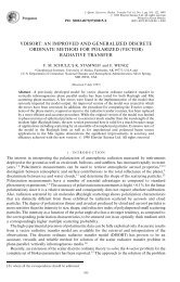
Linearizations. Derivatives of all these expressions may be determined by differentiation withrespect to variable ξ n in layer n. The end-points of the chain rule differentiation are the linearizedoptical property inputs { Vn , U n, Z nl} from Eq. (2.33). For linearization of the homogeneous postprocessingsource term in layer n, there is no dependency on any quantities outside of layer n; in−other words, Lp[ H n( x,μ)]≡ 0 for p ≠ n. The particular solution post-processing source terms inlayer n depend on optical thickness values in all layers above and equal to n through the presenceof the average secant and the solar beam transmittances, so there will be cross-layer derivatives.However, the chain-rule differentiation method is the same, and requires a careful exercise inalgebraic manipulation.Multiplier expressions (2.89), (2.90) and (2.92) have appeared a number of times in theliterature. The linearizations were discussed in [Spurr, 2002] and [Van Oss and Spurr, 2002], andwe need only make two remarks here. Firstly, the real and complex homogeneous solutionmultipliers are treated separately, with the real part of the complex variable result to be used inthe final reckoning. Second, the solar source term multipliers (for example in Eq. (2.92) are thesame as those in the scalar model.Linearizations of the thermal post-processed solution are straightforward; details for the scalarsolution in LIDORT were noted in the review paper [Spurr, 2008].2.4. Spherical and single-scatter corrections in LIDORT2.4.1. Pseudo-spherical approximationThe pseudo-spherical (P-S) approximation assumes solar beam attenuation for a curvedatmosphere. All scattering takes place in a plane-parallel situation. The approximation is astandard feature of many radiative transfer models. We follow the formulation in [Spurr, 2002].Figure 2.2 provides geometrical sketches appropriate to this section.We consider a stratified atmosphere of optically uniform layers, with extinction optical depths{Δ n }, n = 1, N TOTAL (the total number of layers). We take points V n−1 and V n on the vertical(Figure 1, upper panel), and the respective solar beam transmittances to these points are then:n⎡ ⎤= ⎢ − ∑ − 1n⎡ ⎤Tn−1exp s n −1,kΔ k ⎥ ; T n = exp⎢− ∑ s n , kΔk ⎥⎦ . (2.96)⎣ k=1 ⎦⎣ k = 1Here, s n,k is the path distance geometrical factor (Chapman factor), equal to the path distancecovered by the V n beam as it traverses through layer k divided by the corresponding verticalheight drop (geometrical thickness of layer k). At the top of the atmosphere, T0= 1 . In theaverage secant parameterization, the transmittance to any intermediate point between V n−1 and V nis parameterized by:T ( x ) = T exp n−1 [ − λnx], (2.97)where x is the vertical optical thickness measured downwards from V n−1 and λ n the averagesecant for this layer. Substituting (2.97) into (2.96) and setting x = Δ n we find:nn−11 ⎡⎤λn= ⎢∑sn,kΔk− ∑ sn−1, kΔk ⎥ . (2.98)Δn ⎣ k=1k=1 ⎦30
1In the plane-parallel case, we have λ = μ−n 0 for all n.Linearization: We require derivatives with respect to an atmospheric property ξ k in layer k. Thebasic linearized optical property input is the normalized derivativeV n of the layer optical depthextinction Δ n . Applying the linearization operator to (2.98) and (2.96), we find:Figure 2.2. (Upper panel) Pseudo-spherical viewing geometry for scattering along the zenith AC.(Lower panel) Line of sight path AB in a curved atmosphere, with viewing and solar angles changingalong the path from A to B.( − )VL ; L [ ] = 0 ; ( k = n)k[ λn] = sn,nλnΔn( − s )kk[n] sn,k n−1,knkT nVL λ = ; Lk[ Tn]= −Vksn−1,kTn; ( k < n)(2.99)ΔL [ ] = 0 ; L [ ] = 0 ; ( k > n)kλ nkT n31
For the plane-parallel case, we have:VkTnLk[ λ n] = 0 ( ∀ k,∀n); Lk[ Tn] = − ( k < n); k[ ] = 0μL T n ( k ≥ n). (2.100)2.4.2. Exact single scatter solutions0In <strong>VLIDORT</strong>, we include an exact single-scatter computation based on the Nakajima-Tanaka(NT) procedure [Nakajima and Tanaka, 1988]. The internal single scatter computation in<strong>VLIDORT</strong> will use a truncated subset of the complete scatter-matrix information, the number ofusable Legendre coefficient matrices B l being limited to 2N −1 for N discrete ordinate streams.A more accurate computation results when the post-processing calculation of the truncated single− −scatter contribution (the term Qn( μ)En( x,μ)in Eq. (2.86) for example) is suppressed in favor ofan accurate single scatter computation, which uses the complete phase function. This is the socalled TMS procedure [Nakajima and Tanaka, 1988]. This N-T correction procedure appears inthe DISORT Version 2.0 [Stamnes et al., 2000] and LIDORT [Spurr, 2002] codes. A relatedcomputation has been implemented for the doubling-adding method [Stammes et al., 1989].The (upwelling) post-processed solution in stream direction μ is now written (c.f. Eq. (2.86)):I−nQ−−−( Z ( μ)+ Q ( μ)) ( x,μ)−−(Δ−x) / μ −( x,μ)= In( Δ , μ)e + Hn( x,μ)+nn,exactEn, (2.101)ω( I−nn, exactμ)=Πn( μ,μ0,φ − φ0)4π(1 − ωnfn)320. (2.102)Note the presence of in the denominator of the expression ( 1− ω nf )n which is required when thedelta-M approximation is in force; f n is the truncation factor (see section 3.4.1). From section2.1.1, Πn is obtained from the scattering matrix F n (Θ) through application of rotation matrices.There is no truncation: Πn can be constructed to any degree of accuracy using all availableunscaled Greek matrices B nl .Linearization. Chain-rule differentiation of Eq. (2.102) yields the linearization of the exact single−scatter correction term. Linearization of the multiplier En( x,μ)has already been established.Since the elements of Πn consist of linear combinations of Bnl , the linearization Ln( Πn) isstraightforward to write down in terms of the inputs Ln( Bnl) .2.4.3. Sphericity along the line-of-sightFor nadir-geometry satellite instruments with wide-angle off-nadir viewing, one must considerthe Earth’s curvature along the line of sight from the ground to the satellite. This applies toinstruments such as OMI on the Aura platform (swath 2600 km, scan angle 114° at the satellite)[Stammes et al., 1999] and GOME-2 (swath 1920 km) [EPS/METOP, 1999]. Failure to accountfor this effect can lead to errors of 5-10% in the satellite radiance for TOA viewing zenith anglesin the range 55-70° [Spurr, 2003; Rozanov et al., 2000; Caudill et al., 1997]. For LIDORT, asimple correction for this effect was introduced for satellite geometries in [Spurr, 2003].Correction involves an exact single scatter calculation along the line of sight from ground toTOA: in this case, Eq. (2.102) is still valid, but now the geometry is changing from layer tolayer. The same correction has been adopted for <strong>VLIDORT</strong>.
In section 2.4.1, scattering was assumed to take place along the nadir, so that the scatteringgeometry Ω ≡ { μ0 , μ,φ − φ0}is unchanged along the vertical. For a slant line-of-sight path(Figure 2, lower panel), the scattering geometry varies along the path. For layer n traversed bythis path, the upwelling Stokes vector at the layer-top is (to a high degree of accuracy) given by:↑↑↑↑I ( Ωn−1)≅ I ( Ωn) T(Ωn) + Λn( Ωn) + Mn( Ωn) . (2.103)↑Here, I ( Ωn) is the upwelling Stokes vector at the layer bottom, T ( Ωn) the layer transmittance↑along the line of sight, and ( Ω↑Λn n) and Mn( Ω n) are the single- and multiple-scatter layersource terms respectively. The transmittances and layer source terms are evaluated withscattering geometries Ωn at positions V n . Equation (2.103) is applied recursively, starting with↑the upwelling Stokes vector IBOA( ΩNTOTAL)evaluated at the surface for geometry ΩNTOTAL , andfinishing with the field at top of atmosphere (n = 0). The single-scatter layer source terms↑Λn( Ωn) may be determined through an accurate single scatter calculation (cf. Eq. (2.102))allowing for changing geometrical angles along the line of sight. To evaluate the multiple scattersources, we run <strong>VLIDORT</strong> in “multiple-scatter mode” successively for each of the geometriesfrom ΩNTOTAL to Ω1, retaining only the appropriate multiple scatter layer source terms, and, forthe first <strong>VLIDORT</strong> calculation with the lowest-layer geometry ΩNTOTAL , the surface upwelling↑Stokes vector IBOA( Ω NTOTAL).For N TOTAL layers in the atmosphere, we require N TOTAL separate calls to <strong>VLIDORT</strong>, and this ismuch more time consuming that a single call with geometry ΩNTOTAL (this would be the default inthe absence of a line-of-sight correction). However, since scattering is strongest near the surface,the first <strong>VLIDORT</strong> call (with geometryΩNTOTAL ) is the most important as it provides the largest↑scattering source term MNTOTAL( Ω NTOTAL).An even simpler line-of-sight correction is to assume that all multiple scatter source terms aretaken from this first <strong>VLIDORT</strong> call; in this case, we require only the accurate single scattercalculation to complete I↑ TOA. This approximation is known as the “outgoing” sphericitycorrection; it requires very little extra computational effort compared to a single <strong>VLIDORT</strong> call.The sphericity correction can also be set up with just two calls to <strong>VLIDORT</strong> made with the startand finish geometries ΩNTOTAL and Ω1; in this case, multiple scatter source terms at othergeometries are interpolated at all levels between results obtained for the two limiting geometries.In the scalar case, accuracies for all these corrections were investigated in [Spurr, 2003].In <strong>VLIDORT</strong> 2.0, the facility for generating multiple layer source terms has been dropped, asthere has been little usage. However, the outgoing sphericity correction is important, and a newformulation has been developed for this release. This has been validated against the TOMRADcode and is applicable also to the vector <strong>VLIDORT</strong> model. We now describe this.2.4.4. A more accurate outgoing sphericity correctionIn this section, the exposition applies to the scalar intensity, but the treatment is the same for the<strong>VLIDORT</strong> implementation.33
One of the features of the above outgoing sphericity correction is that the average-secantformulation is still assumed to hold for solar beam attenuation. In Eq. (2.102), the layer single−scattering source terms still contain the post-processing multipliers En( x,μ)which were derivedusing the average-secant exponential parameterization in terms of the vertical optical thicknesscoordinate for that layer (Eq. (2.92)).Figure 2 (lower panel) shows the geometry for the single-scattering outgoing sphericitycorrection along the line of sight. In a non-refractive atmosphere, the solar zenith angle, the lineof-sightzenith angles and the relative azimuth angle between the incident and scattering planeswill vary along path AB, but the scattering angle Θ is constant for straight-line geometry.For single scatter along AB, the current implementation in the LIDORT and <strong>VLIDORT</strong> codes isbased on the average secant approximation of the solar attenuation A (x)to a point along thepath with vertical optical thickness x measured from layer-top:1 ⎡ An−⎤A( x)= A n − 1exp[ −xλn]; λn= ln 1⎢ ⎥ . (2.104)Δn ⎣ An⎦Here An−1and An are transmittances to layer top and layer bottom respectively, and Δn is thewhole-layer vertical optical thickness. As noted above, the RTE in layer n is:dI(x)ωnFP(Θ)μn= I(x)+ An( x). (2.105)dx4πHere, μn is the averaged line-of-sight cosine defined as the vertical height difference of layer ndivided by the line-of-sight slant distance; ωn is the layer single scattering albedo with phasefunction Pn(Θ)(both are constants within the layer), and F is the solar flux. In the averagesecantapproximation, Eq. (2.105) has a straightforward solution that utilizes the exponentialdependence of the attenuation to deliver the following closed-form result:[ − snΔn] Jn1−exp[ −( sn+ λn)μ ( s + λ )I ↑ n= I↑−1 nexp + ; (2.106)Jn= HnAn−1nnnΔn]. (2.107)Here, 4 H FP ( Θ−1πn= ωn) and s n= μ n . The TOA result for the upwelling single scatteringradiation field is then found by recursion of Eq. (2.106).IN↑ ↑0= IsurfaceCN+ ∑ JnCn−1; (2.108)n=1n= ∏ exp[ − Δp] ; C0= 1. (2.109)p=1C ns pFor densely layered atmospheres, the average secant approximation is accurate enough for therange of solar angles considered so far. However, it has been shown [Spurr, 2002] that thistreatment loses accuracy for very high SZA and for layers that are optically or geometricallythick. A better treatment of outgoing single scatter is therefore required for the LIDORT codes –one that will produce reliable answers for all applications (not just the Rayleigh scattering UVozonescenarios), and in particular in the presence of cloud layers and for situations involving34
oader layers at high SZA. Further, we want this treatment to be fully linearized, in that theresulting single scatter radiation field can be differentiated with respect to any profile variable forwhich we require Jacobians.It is a feature of the LIDORT and <strong>VLIDORT</strong> codes that layers are considered optically uniform,but for outgoing sphericity corrections, the geometry is variable along the viewing path. Werewrite (2.105) as:dI ( z)μ ( z)= ε nI ( z)+ ε nHnAn( z). (2.110)dzHere, the attenuation A n(z)is computed precisely as a function of the vertical height z, and εn isthe extinction coefficient for the layer (a constant). From geometry, the viewing zenith angle θ isrelated to z through:( R + z0 ) sinθ0sinθ ( z)=. (2.111)R + zHere, R is the Earth’s radius and the subscript “0” indicates values at TOA. Thus,since μ ( z)= cosθ( z), we can change the variable in (2.110) to get:dI(θ)sin 2 θ = knI(θ)+ knHnAn( θ). (2.112)dθHere, kn= εn( R + z0 ) sinθ0 . An integrating factor for this differential equation is k ncotθ ( z),and the whole-layer solution is then:↑ ↑ kn(cotθn−cotθn−1 )InIneJˆ−1= +n ; (2.113)θ nkncot θ−kAn n −neJˆcot θ ( θ )1n= −knHne∫ dθ2 . (2.114)sin θθn −1The integral in (2.114) can be done to a very high degree of accuracy by trapezium-rulesummation. The TOA upwelling intensity is computed with a recursion similar to that in Eq.(2.108). Equation (114) defines the source term for a whole layer; it is also possible to define apartial-layer source term for output at some intermediate point between the layer boundaries.Linearization. We consider differentiation with respect to the inherent optical properties (IOPs)defined for each layer – the extinction coefficientsε n , the scattering coefficients σ n and thephase-function expansion coefficients βnl . We define a linearization operator with respect to avariable ξ p in layer p:∂ynLp( yn) = ξp∂ ξ . (2.115)pIf ξp= εp , then Lp( kn) = δnpknfrom the definition of kn (see after (112)), and L ( H p n) = 0 .Here, δnp is the Kronecker delta. Differentiating (2.113) and (2.114) with respect to εp yields:35
L↑↑ ↑k (cot n −cotn −1)[−1] = { [ ] + (cot − cot−1)} n θ θpInLpInInknδnpθnθne− kn− k Hn( 1−knen−kcotθncotθn−1n−1⎡⎢k⎢⎣) Hθnθnn∫en−1θn−kncot θn−1θ∫n−136An( θ ) edθ2sin θkncotkncotθθnAn( θ ) e cotθLdθ+ ∫ dθ2sin θθθn −1p[ A ( θ )] ensin2θkncot θ⎤⎥ . (2.116)⎥⎦The only new quantity here is L [ A ( θ p n)] in the final integral. To evaluate this, we note that theattenuation of the solar beam to a point z with zenith angle in layer n can be written as:⎡NL⎤A n( θ ) = exp⎢−d np( θ ) ε ⎥p . (2.117)⎢⎣⎥∑= p 1 ⎦Here, dnp(θ ) are geometrical distances independent of the optical properties. The total numberof layers in the atmosphere is NL. It follows that:Lp[ An( θ )] = −dnp( θ ) εpAn( θ ) . (2.118)All integrals in the last line of Eq. (2.116) can again be done accurately using trapezium rulesummations. The linearization was checked using finite difference estimates.For most geometrical situations, d ( θ ) = np0 for all layers p > n; this corresponds to points on theline of sight that are illuminated from above. In this case, the attenuation does not depend onextinction coefficients in layers below n, and hence L [ A p n( θ )] = 0 for p > n. However, there aresituations (near the top of the atmosphere for a wide off-nadir viewing path and a high solarzenith angle) in which some points along the line-of-sight are illuminated by direct sunlightcoming from below the horizontal. In this case, the solar path has gone through a tangent heightin the atmosphere, and dnp(θ ) is not necessarily zero for p >n.For a differentiation with respect to other optical properties, the situation is simpler. Definingnow a linearization:Lq qσ ; (2.119)q= σ ∂∂with respect to the scattering coefficient σq in layer q, the only non-vanishing term arising in thelinearization of (2.114) is Lq[Hn] = Hnδnq , so that we have:nkncot θ↑↑ kn(cot θ n −cotθ n −1)−kncot θ n −1Lq[ In−1]= Lq[In] e− δnqknHnedθ2 . (2.120)NOTE. <strong>VLIDORT</strong> as a single-scatter RT modelθθ∫n −1A(θ ) esin θFollowing user feedback from a number of individuals, <strong>VLIDORT</strong> (and LIDORT) have nowbeen given a stand-alone single-scatter capability. This is controlled by a single flag, which if set,ensures that the multiple scatter calculation is avoided and the model returns only the singlyscattered radiances and Jacobians. The above single scatter corrections then apply foratmospheric scattered light; and it is only necessary to include for the upwelling field the
transmitted direct-beam reflectance. We also note that an additional delta-M scaling procedurehas been optionally included for the single scatter computation. When the model is running withmultiple scatter included, then this additional scaling can be applied on top of the usual delta-Mscaling applied to the truncated phase function in the diffuse field equations; in this case theNakajima-Tanaka TMS procedure still applies. With <strong>VLIDORT</strong> in single-scatter-only mode, theoriginal diffuse-field delta-M scaling is not required, though the additional truncation can still beapplied if desired.2.5. Bulk (total column) atmospheric Jacobians.One of the most important applications for <strong>VLIDORT</strong> has been in forward model simulations forozone profile and total column retrieval. The use of total column as a proxy for the ozone profilewas recognized a number of years ago by scientists at NASA, and column-classified ozoneprofile climatologies were created for the TOMS Version 7 [Wellemayer et al., 1997] and morerecently for Version 8 retrieval algorithms [Bhartia, 2003]. If the profile is represented as a set{ Uj } of partial columns in Dobson Units [DU], then the total column (also in [DU]) isC = ∑U j . For two adjacent TOMS profiles { (1)(2)Ujj} and { Uj } with total columns C (1) andC (2) we define an intermediate profile with column amount C according to:(1)(2)⎛ C − C ⎞(2)⎛ C − C (1)Uj( C)U(2) (1) jU(2) (1) jC C C C⎟ ⎞= ⎜⎟ +⎜. (2.121)⎝ − ⎠ ⎝ − ⎠This defines the profile-column map; it is linear in C. Total column weighting functions arerelated to profile Jacobians by means of chain rule differentiation and the partial derivative:∂Uj( C)U=∂CC(2)j(2)−U− C(1)j(1). (2.122)This map allows us to interpolate smoothly between profile entries in the climatology. In effect,we are drawing on an ensemble of possible profiles of which the climatology is a sample. Othermaps are possible. TOMS Version 8 profiles are specified for 18 latitude bands from pole to pole(10° intervals), and for each month of the year.Suppose now we have a Rayleigh atmosphere with Rayleigh scattering cross-section σ Ray (λ), aircolumn density D p in layer p, ozone partial columns U p , and temperature-dependent ozone crosssections σ O 3p( λ); then the bulk property IOPs are:RayOΔp= σ ( λ)Dp+ σ 3p( λ)Up ;37σ(λ) DRayωp=p;Δp(2.123)Differentiating (2.122) with respect to U p gives the linearized IOP inputs for the profile Jacobian:∂ΔpU =p(σ O 3pλ) ;∂ωpωp∂Δ= −∂U Δ ∂UFinally, we compute the column Jacobian using the chain rule:Kcolnpppp. (2.124)∂I(0, Ω)∂I(0,Ω)∂Up( Ω ) =. (2.125)∂C∂U∂C≡ ∑=1 pp
Note the use of the profile-column mapping derivatives ∂ U p∂ C . Merely adding up the partialcolumn weighting functions is equivalent to assuming that the response of the TOA field tovariations in total ozone is the same for all layers – the profile shape remains the same. Equation(2.125) is the correct formula to account for shape variation.It is perfectly possible to set up <strong>VLIDORT</strong> to deliver a set of profile Jacobians; a columnweighting function would then be created externally from the sum in Eq. (2.125). This is notvery efficient, since for a 13-layer atmosphere, it requires us to calculate 13 separate profileweighting functions and then sum them. However, a facility was introduced in the scalarLIDORT code Version 2.5 to have LIDORT calculate the column Jacobian directly; in effect, thesummation in Eq. (2.125) is done internally. This is a much more efficient procedure. In this casethe linearized IOP inputs are expressed in terms of the profile-column mapping derivatives:∂Δp∂C= σO 3p( λ∂Up) ;∂C∂ωp∂Cωp= − σΔpO 3p( λ∂Up) . (2.126)∂CThis feature has been retained in all LIDORT Version 3 codes, and the single-scatter corrections(outgoing and nadir), surface treatments and performance enhancements (in particular thelinearization of the reduced BVP problem) have been upgraded to ensure that the columndifferentiation is done internally inside LIDORT if the requisite flag is turned on for columnlinearization. The model will generate either profile or column Jacobians for atmosphericquantities.38
3. The numerical <strong>VLIDORT</strong> model3.1. Preparation of inputs3.1.1. Basic optical property inputsIn this section, we give a brief introduction to the input requirements for <strong>VLIDORT</strong>, in particularthe determination of optical property inputs (including linearized quantities). It is already clearthat for a Stokes vector computation using <strong>VLIDORT</strong>, we require the input set {Δ n , ω n , B nl } foreach layer n, where Δ n is the total optical thickness, ω n the total single scatter albedo, and B nl theset of Greek matrices specifying the total scattering law. The form for B nl is given in Eq. (2.24)in terms of the six Greek constants {α l , β l , γ l , δ l , ε l , ζ l } which must be specified for each momentl of a Legendre function expansion in terms of the cosine of the scattering angle. The values β lare the traditional phase function expansion coefficients, the ones that appear as inputs to thescalar version; they are normalized to 4π.As an example, we consider a medium with Rayleigh scattering by air molecules, some trace gasabsorption, and scattering and extinction by aerosols. Dropping the layer index, if the layerRayleigh scattering optical depth is δ Ray and trace gas absorption optical thickness α gas , with theaerosol extinction and scattering optical depths τ aer and δ aer respectively, then the total opticalproperty inputs are given by:Δ = αgas+ δRay+ τaer ;δ aer+ δ Rayω = ;ΔδB ,+ δ B ,Ray l Ray aer l aerBl=δRay+ δ. (3.1)aerThe Greek matrix coefficients for Rayleigh scattering are given by the following table.α l β l γ l δ l ε l ζ ll=0 0 1 0 0 0 0l=1 0 0 0 3(1− 2ρ)0 02 + ρl=2 6(1 − ρ)(1 − ρ)6(1− ρ)0 0 02 + ρ 2 + ρ−2 + ρFor zero depolarization ratios, the only surviving Greek constants are: β 0 = 1.0, β 2 = 0.5, α 2 =3.0, γ 2 = −√6/2 and δ 1 = 1.5. Aerosol quantities must in general be derived from a suitableparticle scattering model (Mie calculations, T-matrix methods, etc.).We consider a 2-parameter bimodal aerosol optical model with the following combined opticalproperty definitions in terms of the total aerosol number density N and the fractional weighting fbetween the two aerosol modes:Δ aer= Ne aer≡ N[ fe1 + (1 − f ) e2]; (3.2a)aerfz1 e1+ ( 1−f ) z2e2ωaer≡eaere; (3.2b)aer= σ39
βl,aer(1)(2)fz1e1βl+ ( 1−f ) z2e2βl= . (3.2c)σaerThe quantity σ aer is the combined scattering coefficient and e aer the combined extinctioncoefficient. In Eq. (3.2c) we have given the combined expression for just one of the Greekconstants; the other 5 are constructed in a similar fashion. Thus, the quantity β l,Aer is the l-thcoefficient in the Legendre polynomial expansion of the phase function. Here, e 1 , z 1 and arethe extinction coefficient, single scatter albedo and Legendre expansion coefficient for aerosoltype 1; similar definitions apply to aerosol type 2.3.1.2. Linearized optical property inputsFor the linearized inputs with respect to a parameter ξ for which we require weighting functions,we define normalized quantities:ξ ∂Δξ ∂ωξ ∂Blφ ξ=Δ ∂ξ; ϕ ξ=ω ∂ξ; Ψl , ξ=B ∂ξ. (3.3)lThese may be established by differentiating the definitions in Eq. (3.1). We give one examplehere: if there is a single absorbing gas (ozone, for example), with C the partial column of tracegas in any given layer, and σ gas the absorption coefficient, then we have Δ = Cσ gas+ δRay+ τaerin the above equations. For trace gas profile Jacobians, we require the derivatives in Eq. (3.3) asinputs, taken with respect to C. These are:C ∂ΔCσgasφC≡ = ;Δ ∂CΔC ∂ωCσgas ξ ∂BlϕC≡ = − ; Ψl, ξ≡ = 0ω ∂CΔB ∂ξ. (3.4)Jacobian parameters may be elements of the retrieval state vector, or they may be sensitivityparameters which are not retrieved but will be sources of error in the retrieval. As anotherexample (keeping to the notation used for the above bi-modal aerosol model), we will assumethat the retrieval parameters are the total aerosol density N and the bimodal ratio f. All otherquantities in the above definitions are sensitivity parameters.For the retrieval Jacobians (with respect to N and f) the relevant inputs are found by partialdifferentiation of the definitions in Eq. (3.1). After some algebra, one finds (we have justconsidered one for the Greek-matrix elements for simplicity):∂Δ∂ΔN = N∂N∂N∂ωN =∂NβN =∂NNσaeraerNσNσ= Δ− ωΔaerΔ aer∂ l aer l , aer∂Δ∂Δaer; f = f = fN( e 1− e2) ; (3.5a)∂f∂f;( β − β )aer+ σRayl;∂ωf =∂fffNl[( z e − z e ) − ω( e −2)]1 1 2 2 1eaerΔ( β − β )∂ β fN(z e − z el1 1 2 2)l , aer∂f=Nσ+ σRaylβ(1)l; (3.5b). (3.5c)For sensitivity Jacobians, the quantities σ Ray , α gas , e 1 , z 1 , e 2 and z 2 are all bulk property modelparameters that are potentially sources of error. [We can also consider the phase functionquantities γ Ray , γ 1 and γ 2 as sensitivity parameters, but the results are not shown here]. After a lot40
more algebra (chain rule differentiation, this time not normalizing), we find the followingderivatives:∂Δ= 1∂ ω − ω∂ ; =1ll Ray l∂σΔ ;∂ β β − β=,; (3.6a)∂σNσ+ σσ RayRayRayaerRay∂Δ∂α Gas1= 1;∂ΔNf∂e = ;∂Δ∂e2∂Δ∂z∂Δ∂z21= N= 0 ;= 0;( 1−f );∂ω∂αGasω= −Δ∂ω Nf ( z 1− ω)=∂eΔ1∂ω N( 1−f )( a2− ω)=∂eΔ;2∂ω∂z =21∂ω=∂zNfeΔ1∂βl; = 0∂α; (3.6b);N( 1−f ) eΔ2;;Gasβ=∂efzNσ( β − β )∂ l 1 l , aer1aerβ (1 − f ) z=∂eNσ+ σaerlRay; (3.6c)( β − β )∂ l2 l , aer2β=∂zfeNσ+ σRay( β − β )∂ l 1 l , aer1aerβ (1 − f ) e=∂zNσ+ σaerlRay( β − β )∂ l2 l , aer2+ σRayl; (3.6d); (3.6e)l. (3.6f)3.1.3. Additional atmospheric inputs<strong>VLIDORT</strong> is a pseudo-spherical model dealing with the attenuation of the solar beam in acurved atmosphere, and it therefore requires some geometrical information. The user needs tosupply the earth’s radius R earth and a height grid {z n } where n = 0, 1, ... NLAYERS (the totalnumber of layers); heights must be specified at layer boundaries with z 0 being the top of theatmosphere. This information is sufficient if the atmosphere is non-refracting.If the atmosphere is refracting, it is necessary to specify pressure and temperature fields {p n } and{t n }, also defined at layer boundaries. The refractive geometry calculation inside <strong>VLIDORT</strong> isbased on the Born-Wolf approximation for refractive index n(z) as a function of height:n( z)= 1+α0p(z) / t(z). Factor α 0 depends slightly on wavelength, and this must be specified bythe user if refractive bending of the solar beams is desired. To a very good approximation it isequal to 0.000288 multiplied by the air density at standard temperature and pressure. <strong>VLIDORT</strong>has an internal fine-layering structure to deal with repeated application of Snell’s law. In thisregard, the user must specify the number of fine layers to be used for each coarse layer (10 isusually sufficient).3.1.4. Surface property inputsThe kernel-based BRDF treatment has now been separated from the main <strong>VLIDORT</strong> code.Calculation of the BRDF kernels and Fourier components of the BRDF is now performed in adedicated BRDF supplement. Thus, <strong>VLIDORT</strong> now receives total BRDFs and their Fouriercomponents (and if required, the surface-property linearizations of these quantities), withoutknowledge of the individual kernels used to construct these quantities. A brief description of theavailable BRDF kernels and their inputs are given here. For a fuller treatment, consult the BRDFsupplement appendix (section 6.3).41
For BRDF input, it is necessary for the user to specify up to three amplitude coefficients {R k }associated with the choice of kernel functions, and the corresponding vectors {b k } of non-linearcoefficients. For example, if the BRDF is a single Cox-Munk function, it is only necessary tospecify the wind speed (in meters/second) and the relative refractive index between water andair. Table 3.1 lists the available kernel functions found in the <strong>VLIDORT</strong> BRDF supplement.Table 3.1. Summary of BRDF kernels available in the <strong>VLIDORT</strong> BRDF supplement# Kernel Name # parameters type Source1 Lambertian 0 Scalar ----2 Ross-thick 0 Scalar Wanner et al., 19953 Ross-thin 0 Scalar MODIS4 Li-sparse 2 Scalar MODIS5 Li-dense 2 Scalar MODIS6 Roujean 0 Scalar MODIS7 Rahman(RPV) 3 Scalar Rahman et al., 19938 Hapke 3 Scalar Hapke, 19939 Cox-Munk 2 Scalar Cox/Munk, 195410 GISS Cox-Munk 2 Vector Mishchenko/Travis 199711 GISS Cox-Munk CRI 2 Vector Natraj, 2012 (personalcommunication)12 BPDF 2009 2 Vector Maignan et al., 2009It will be noticed that most options are “scalar”, that is reflectance is only applied to the totalintensity part of the Stokes vector, and the BRDF matrix is non-zero only for the (1,1)component. The specular reflection of polarized light from randomly reflecting surfaces is wellknown, and the glitter BRDF (“GISS Cox-Munk”) is based on software available from theNASA GISS site, with formalism described in the paper by [Mishchenko and Travis, 1997]. Forland surfaces, there is a dearth of source material in the literature but some reasonably accurateempirically-based kernels have been developed in recent years from analyses of POLDER andMISR data [Maignan et al., 2009]. The <strong>VLIDORT</strong> implementation (BPDF 2009 in Table 3.1) isincluded by kind permission of the authors.Note we do not need to specify full tables of BRDF values for each Fourier component. Thesupplement has BRDF routines for calculating values of the kernel functions for all possiblecombinations of angles, and additional routines for delivering the Fourier components of thekernel functions. Fourier component specification is done numerically by integration over theazimuth angle, and for this, it is necessary to specify the number of BRDF azimuth quadratureabscissa N BRDF . The choice N BRDF = 50 is sufficient to obtain numerical accuracy of 10 -4 in thisFourier component calculation. Nonetheless, the user is allowed to choose N BRDF .For surface property weighting functions, we need only specify whether we require weightingfunctions with respect to {R k } and/or to the components of vectors {b k }. Additional inputs arethus restricted to a number of Boolean flags; the BRDF supplement takes care of the rest.3.1.5. Thermal emission inputsFor atmospheric thermal emission input, the current specification in <strong>VLIDORT</strong> requires thePlanck Black-body function to be input at layer boundaries. The surface emission input requiresa separate Planck function as input. A convenient routine for generating the integrated Planckfunction in [W.m -2 ] was developed as an internal routine for the DISORT code [Stamnes et al.,42
2000]; this can be used outside the <strong>VLIDORT</strong> environment to generate the required Planckfunctions. This Planck function generator has been linearized with respect to temperature, so thatall thermal source terms are differentiable for temperature retrievals.For thermal emission alone, Planck functions are specified in physical units (the usual unit is[W.m -2 .ν -1 ]. For solar sources only, output is normalized to the input solar flux vector (which canbe set to arbitrary units). For calculations with both sources, the solar flux must be specified inthe same physical unit as that for the Plank function input.3.2. Validation and benchmarking3.2.1. Checking against the scalar code<strong>VLIDORT</strong> is designed to work equally with Stokes 4-vectors {I,Q,U,V} and in the scalar mode(I only). The first validation task for the vector model is to run it in scalar mode and reproduceresults generated independently from the scalar LIDORT model. A set of options can be used totest the major functions of the model (the real RT solutions, the boundary value problem andpost processing) for the usual range of scenarios (single layer, multilayer, arbitrary level outputand viewing angles, plane-parallel versus pseudo-spherical, etc.). This battery of tests is veryuseful, but of course it does not validate the Stokes-vector solutions and in particular thecomplex variable RTE formalism (absent in the scalar RT).In this section, we make one important point concerning the verification of the multi-layercapability. This can easily be tested using the invariance principle: two optically identical layersof optical thickness values x 1 and x 2 will (at least for plane-parallel geometry) produce a fieldequivalent to that produced by an optically identical layer of thickness x 1 + x 2 . This appliesequally to the scalar and vector models. This technique is particularly useful for testingimplementations of the boundary value linear algebra solution (section 2.3.1). We now turn toverification using slab problem results.3.2.2. The Rayleigh slab problemA first validation was carried out against the Rayleigh atmosphere results published in the tablesof Coulson, Dave and Sekera [Coulson et al., 1960]. These tables apply to a single-layer pureRayleigh slab in plane parallel geometry; the single scattering albedo is 1.0 and there is nodepolarization considered in the scattering matrix. Tables for Stokes parameters I, Q and U aregiven for three surface albedos (0.0, 0.25, 0.80), a range of optical thickness values from 0.01 to1.0, for 7 azimuths from 0° to 180° at 30° intervals, some 16 view zenith angles with cosinesfrom 0.1 to 1.0, and for 10 solar angles with cosines from 0.1 to 1.0. With the single scatteringalbedo set to 0.999999, <strong>VLIDORT</strong> was able to reproduce all these results to within the levels ofaccuracy specified in the introduction section of the CDS tables.3.2.3. Benchmarking for aerosol slab problemsThe benchmark results noted in [Siewert, 2000b] were used; all 8 output tables in this work werereproduced by <strong>VLIDORT</strong>. The slab problem used a solar angle 53.130° (μ 0 = 0.6), with singlescatter albedo ω = 0.973527, surface albedo 0.0, total layer optical thickness of 1.0, and a set ofGreek constants as noted in Table 1 of [Siewert, 2000b]. Output was specified at a number ofoptical thickness values from 0 to 1, and at a number of output streams. 24 discrete ordinate43
streams were used in the half space for the computation. In Table 3.2, we present <strong>VLIDORT</strong>results for intensity at relative azimuth angle of 180°; the format is deliberately chosen to mimicthat used in [Siewert, 2000b]. It is clear that the agreement with his Table 8 is almost perfect.The only point of issue is the downwelling output at μ = 0.6: this is a limiting case because μ 0 =0.6 as well. Such a case requires l'Hopital's rule to avoid singularity, and this has beenimplemented in <strong>VLIDORT</strong> (as in LIDORT), but had not discussed in Siewert's paper. All tablesin [Siewert, 2000a] were reproduced, with differences of 1 or 2 in the sixth decimal place(excepting the above limiting case).Table 3.2 Replica of Table 8 from [Siewert, 2000b].0.000 0.125 0.250 0.500 0.750 0.875 1.000-1.0 5.06872E-02 4.26588E-02 3.45652E-02 1.97273E-02 7.87441E-03 3.36768E-03-0.9 4.49363E-02 3.83950E-02 3.16314E-02 1.87386E-02 7.81148E-03 3.42290E-03-0.8 4.95588E-02 4.29605E-02 3.59226E-02 2.19649E-02 9.46817E-03 4.21487E-03-0.7 5.54913E-02 4.89255E-02 4.16034E-02 2.63509E-02 1.18019E-02 5.35783E-03-0.6 6.19201E-02 5.57090E-02 4.83057E-02 3.18640E-02 1.49296E-02 6.94694E-03-0.5 6.84108E-02 6.30656E-02 5.59610E-02 3.87231E-02 1.91563E-02 9.19468E-03-0.4 7.44303E-02 7.06903E-02 6.44950E-02 4.72940E-02 2.50375E-02 1.25100E-02-0.3 7.89823E-02 7.78698E-02 7.35194E-02 5.79874E-02 3.35858E-02 1.77429E-02-0.2 8.01523E-02 8.29108E-02 8.16526E-02 7.07286E-02 4.66688E-02 2.69450E-02-0.1 7.51772E-02 8.29356E-02 8.56729E-02 8.26216E-02 6.65726E-02 4.61143E-02-0.0 5.93785E-02 7.61085E-02 8.33482E-02 8.76235E-02 8.22105E-02 7.53201E-020.0 7.61085E-02 8.33482E-02 8.76235E-02 8.22105E-02 7.53201E-02 6.04997E-020.1 4.81348E-02 7.00090E-02 8.63151E-02 8.80624E-02 8.49382E-02 7.76333E-020.2 2.95259E-02 5.13544E-02 7.72739E-02 8.77078E-02 8.84673E-02 8.55909E-020.3 2.07107E-02 3.91681E-02 6.67896E-02 8.29733E-02 8.70779E-02 8.79922E-020.4 1.58301E-02 3.14343E-02 5.81591E-02 7.72710E-02 8.36674E-02 8.74252E-020.5 1.28841E-02 2.64107E-02 5.17403E-02 7.22957E-02 8.01999E-02 8.60001E-020.6 1.10823E-02 2.32170E-02 4.74175E-02 6.88401E-02 7.78121E-02 8.51316E-020.7 1.01614E-02 2.15832E-02 4.53651E-02 6.77032E-02 7.75916E-02 8.61682E-020.8 1.03325E-02 2.19948E-02 4.67328E-02 7.07013E-02 8.16497E-02 9.14855E-020.9 1.31130E-02 2.72721E-02 5.64095E-02 8.41722E-02 9.68476E-02 1.08352E-011.0 4.54878E-02 8.60058E-02 1.53099E-01 2.03657E-01 2.23428E-01 2.39758E-01An additional benchmarking for <strong>VLIDORT</strong> Version 2.0 and higher was done against the resultsof Garcia and Siewert [Garcia and Siewert, 1989] for another slab problem, this time withalbedo 0.1. With <strong>VLIDORT</strong> set to calculate using only 20 discrete ordinate streams in the halfspace, tables 3-10 in [Garcia and Siewert, 1989] were reproduced to within 1 digit of sixsignificant figures. This result is noteworthy because the radiative transfer computations in thispaper were done using a completely different radiative transfer methodology (the so-called F Nmethod).3.2.4. Weighting function verificationFor the verification of analytically calculated Jacobians, it is only necessary to validate thederivative by using a finite difference estimate (ratio of the small change in the Stokes vectorinduced by a small change in a parameter in one layer):∂IδIKξ≡ ≈∂ξδξ. (3.7)This applies equally to column and surface Jacobians. The <strong>VLIDORT</strong> version 2.4 tests containanalytic Jacobians that have been validated by finite differences, and the installation programcontains software to carry out this validation for all types of Jacobians44
Verification of each stage of the linearization may also be done in this way. A word is in orderabout the use of finite differences in general. It is of course always possible to attempt weightingfunction estimations using finite difference methods. However, there are pitfalls associated withthis procedure (quite apart from the arbitrariness and time-consuming nature of the exercise). Incertain situations, a small perturbation of one or more of the Greek constants can give rise to aset of eigensolutions which cannot be compared (in a finite-difference sense) with thosegenerated with the original unperturbed inputs. This numerical difficulty sometimes occurs withlower-precision codes.3.3. Performance considerations3.3.1. The delta-M approximationIn the scalar model, sharply peaked phase functions are approximated as a combination of adelta-function and a smoother residual phase function. This is the delta-M approximation[Wiscombe, 1977], which is widely used in discrete ordinate and other RT models. The delta-Mscaled optical property inputs (optical thickness, single scatter albedo, phase function Legendreexpansion coefficients) are:τ = τ ( 1−ωf) ;(1 − f )ω = ω(1 − ωf);The delta-M truncation factor is:β2Nf =(2N+ 1)l− f (2l+ 1)βl= β. (3.8)(1 − f ). (3.9)In <strong>VLIDORT</strong>, Legendre coefficients β l appear as the (1,1) entry in matrix B l . In line with thescalar definition in terms of the phase function, we take in <strong>VLIDORT</strong> the truncation factor f asdefined Eq. (3.9), and adopt the following scaling for the six entries in B l . Four coefficients (α l ,β l , ζ l and δ l ) will scale as β l in Eq. (3.8), while the other two coefficients γ l and ε l scale~as γl= γl(1 − f ) . This specification can also be found in [Chami et al., 2001] where a moredetailed justification is presented. Scaling for the optical thickness and single scatter albedo inEq. (3.8) is the same in the vector model. Linearizations of Eqs. (3.8) and (3.9) arestraightforward, and these are discussed in [Spurr, 2002] for the scalar model.3.3.2. Multiple solar zenith angle facilityIn solving the RTE, the first step is always to determine solutions of the homogeneous equationsin the absence of solar sources. This process does not need to be repeated for each solar beamsource. In DISORT and earlier versions of LIDORT, only one solar zenith angle is specified, andthe models must be called from scratch every time results are required for a new solar geometry.In the new code, the homogeneous solution is solved once before the loop over each solarconfiguration starts; for each solar beam geometry g, we generate a set of particular integralsolutions P g for our multi-layer atmosphere.In solving the boundary value problem, we apply boundary conditions at all levels in theatmosphere, ending up with a large but sparse linear algebra system in the form AX g = B g . Here,X g is the vector of integration constants appropriate to solar beam with geometry g, B g is thesource term vector consisting of contributions from the set of particular solutions P g , and the45
anded tri-diagonal matrix A contains only contributions from the RTE homogeneous solutions.The inverse matrix A -1 can be determined once only, before the loop over solar geometry starts.This is the most time consuming step in the complete solution for the RT field, and oncecompleted, it is straightforward and fast to set the integration constants X g = A -1 B g by backsubstitution.In summary then, two important operations on the homogeneous RT field are carried out beforeany reference to solar beam terms. Thus, the <strong>VLIDORT</strong> code has an internal loop over SZAangles. It is well known that convergence of the Fourier cosine azimuth series for the radiationfield depends on the solar beam angle. We keep track of the convergence separately for eachSZA; once the intensity field at our desired output angles and optical depths has converged forone particular SZA, we stop further calculation of Fourier terms for this SZA, even thoughsolutions at other SZAs still require further computation of Fourier terms.This multiple SZA feature was implemented at the outset in <strong>VLIDORT</strong>. This is a very substantialperformance enhancement for <strong>VLIDORT</strong>, particularly in view of the increased time taken overthe eigenproblem and the much larger BVP matrix inversion compared with the scalar code.3.3.3. Eigensolver usageWe have already noted differences between the LAPACK solver DGEEV and the condensedversion ASYMTX as used in LIDORT and DISORT. DGEEV must be used for any layers withscattering by aerosols or clouds, since there will be complex roots in this case. ASYMTX onlydeals with real symmetric eigenmatrices. Linearization of the homogeneous solutions fromDGEEV uses adjoint theory and has some subtleties; adjoint solutions are not available forASYMTX.It turns out that, aside from additional elements down the diagonal, the eigenmatrix Γ n in layer nTconsists of blocks of 4x4 matrices of the form Plm( μi) BnlPlm( μj) , where the P and B nl matriceswere defined in Eq. (2.24) and (2.25) in section 2.1.1, μi are the discrete ordinates, and the ‘T’superscript denotes matrix transpose. Since P and P T are symmetric, then Γ n will be symmetric ifΒ nl is. Thus, Γ n will be symmetric if the Greek constants ε l in Β nl are zero for all values of l. Thisis a special case satisfied by the Rayleigh scattering law, but in general, this is not true forscattering with aerosols and clouds.For aerosols and clouds, we require the complex eigensolver DGEEV from LAPACK, but forRayleigh scattering we can use the faster “real-only” ASYMTX package. Our policy in<strong>VLIDORT</strong> will be to retain both eigensolvers and use them as appropriate – if any of the Greekconstants ε l in Β nl is non-zero for a given scattering layer, then we will choose the complexeigensolver in that layer. The use of ASYMTX and its linearization for Rayleigh layers willrepresent a considerable saving in processing time. For an application with a few particulatelayers in an otherwise Rayleigh-scattering atmosphere, both eigensolvers will be required.In version 2.4, <strong>VLIDORT</strong> can run with 2 or 3 Stokes vectors instead of the full 4. This is helpfulfor atmospheric simulations, since circular polarization in the Earth’s atmosphere is typicallythree orders of magnitude smaller that its linear counterpart. For a 3-component calculation of I,Q, and U, the model uses 3x3 Mueller and scattering matrices, with the (3,4) and (4,4) elementsof the Greek matrix omitted. In this case, the eigenproblem has real-valued solutions only, and this contributes to the substantial performance savings to be gained with this reduced problem.46
3.3.4. Solution savingIn DISORT and earlier LIDORT versions, the models contained full computations of all RTEsolutions in all layers and for all Fourier components contributing to radiance outputs. Thesesolutions are computed regardless of the scattering properties of the layer: the RTE is solved byfirst calling an eigensolver routine for homogeneous solutions, and then by solving a linearalgebra or Green’s function problem to determine solar-forcing particular solutions. If there is noscattering for a given Fourier component m and layer n, then the RTE solution is trivial – it isjust the extinction across the layer with transmittance factors T n (μ) = exp[-Δ n /μ], where μ is anypolar direction and Δ n is the layer optical thickness.The “solution saving” option is to skip numerical computations of homogeneous and particularsolutions in the absence of scattering. In this case, if there are N discrete ordinates μ j in the halfspace,then the j th homogeneous solution vector X j is trivial: it has components {X j } k = δ jk .Separation constants are μ j −1 , with whole-layer transmittances given by T n (μ j ). Particular solutionvectors are set to zero, since there is no solar beam scattering. Source function integrationrequired for post-processing the solution at arbitrary polar direction is then a simpletransmittance recursion using factors T n (μ). Linearizations (optical parameter derivatives) ofRTE solutions in any non-scattering layer are zero, and linearized solutions in adjacent scatteringlayers will be transmitted with factors T n (μ). We note that if this transmittance propagationpasses through layer n for which a linearization L[Δ n ] exists, then the linearization will pick upan additional term L[T n (μ)] = −μ −1 T n (μ) L[Δ n ].Rayleigh scattering has a P(Θ) ~ cos 2 Θ phase function dependency on scattering angle Θ. Thereis no scattering for Fourier components m > 2; solution saving then applies to “Rayleigh layers”for m > 2. For an atmosphere with Rayleigh scattering and a limited number of aerosol or cloudlayers, there will be a substantial reduction in RTE solution computations is the solution savingoption applies, and consequently a marked improvement in performance. In general, the phasefunction has a Legendre polynomial expansion Φ(Θ) ~ ∑ β λ P λ (cosΘ) in terms of momentcoefficients β λ . For a discrete ordinate solution with N streams, the phase function is truncated:β 2Ν−1 is the last usable coefficient in the multiple scatter solution. In the delta-M approximation,β 2Ν is used to scale the problem and redefine the β λ for 0 ≤ λ ≤ 2Ν−1. Solution saving occurswhen β λ = 0 for m ≤ λ ≤ 2N−1; there is then no scattering for Fourier component m and higher.3.3.5. BVP telescopingFor some Fourier component m, we consider a single active layer with non-trivial RTE solutions;all other atmospheric layers have no scattering (the extension to a number of adjacent activelayers is easy). Integration constants L n and M n in layer n are given throughI±N( x,μi) = ∑α = 1xk α xk α ( x)−± − nm − n Δ n − ± μ0[ L X e + M X e ] + G enαinαnαinαin. (3.10)Here, X nα and k nα denote the homogeneous solution vectors and separation constantsrespectively, G n are the solar source vectors (a plane-parallel solution has been assumed). Theboundary value problem (BVP) for the entire atmosphere is posed by compiling boundaryconditions at all levels to create a large sparse linear algebra system. The BVP matrix has size2NS, where S is the total number of layers, and although there are band compression algorithms47
in place to aid with the LU-decomposition and inversion of this matrix, the BVP solution step isthe most expensive CPU process in the LIDORT code.Let us assume that n is an “active” layer with scattering particles in what is otherwise a nonscatteringRayleigh atmosphere. Then we have X ipα±±= δ i α and Gip= 0 for all Fourier m > 2 andfor all layers p ≠ n. In this case the downwelling and upwelling solutions are:II↓pj↑pj( x)= Lpjexp[ − x μj]; (3.11a)( x)= Mpjexp[ −(Δp− x)μj] . (3.11b)Boundary value constants will clearly propagate upwards and downwards through all these nonscatteringlayers via:Lp+ 1,j= Lpjexp[ −Δpμj]; (3.12a)Mp− 1,j= Mpjexp[ −Δpμj] . (3.12b)If we can find BVP coefficients L n and M n for the active layer n, then coefficients for all otherlayers will follow by propagation. We now write down the boundary conditions for layer n. Atthe top of the active layer, we have:N+−+∑[ LnXinα+ MnαXinαΘnα] + Gin= Ln−1, iCn−1,iα = 1α ; (3.13a)N−+−∑[ LnXinα+ MnαXinαΘnα] + Gin= Mn−1,iα = 1α . (3.13b)At the bottom of the active layer, we haveN+− +∑[ LnXinαΘnα+ MnαXinα] + GinΛnα= Ln+1,iα = 1α ; (3.14a)N−+ −∑[ LnXinαΘnα+ MnαXinα] + GinΛnα= Mn+1, iCn+1,jα = 1α . (3.14b)We have used the following abbreviations:Θnα = exp[ −k nαΔn], Δn= exp[ −η nΔn], Cnj= exp[ −Δnμj]. (3.15)We now consider the top and bottom of atmosphere boundary conditions. At TOA, there is nodiffuse radiation, so that L p = 0 for p = 1 and hence by Eq. (3.12a) also for all p < n. At BOA,the Lambertian reflection condition only applies to Fourier m = 0; for all other components thereis no reflection, and so in our case M p = 0 for p = S and hence by Eq. (3.12b) also for all p > n.With these conditions, Eqs. (3.13a) and (3.13b) become:N+−+∑[ LnXinα+ MnαXinαΘnα] = −Ginα = 1α ; (3.16a)N−+−∑[ LnαXinαΘnα+ MnαXinα] = −GinΛnαα = 1. (3.16b)48
This is a 2N system for the desired unknowns L n and M n (there is actually no band-matrixcompression for a single layer). For the layer immediately above n, we use (3.13b) to find M n-1and for remaining layers to TOA we use (3.12b). Similarly for the layer immediately below n,we use (3.14a) to find L n+1 and for remaining layers to BOA, we use (3.12a). This completes theBVP telescoping process.If the telescoped BVP is written as AY=B, then the corresponding linearized problem may bewritten AL k [Y]=B*=L k [B]−L k [A]Y; the k subscript refers to the layer for which weightingfunctions are required. The latter is essentially the same problem with a different source vector,and the solution may be found be back-substitution, since the matrix inverse A −1 is alreadyknown from the original BVP solution. Construction of the source vector B* depends on theRTE solution linearizations; clearly if k = n there will be more contributions to consider than if k< n. However the linearized boundary conditions for B* are essentially the same as those notedfor the full atmosphere problem – the only thing to remember is that the upper boundary is thesame as TOA but with the first layer active, and the lower boundary is the same as BOA but withthe last layer active.NOTE: this treatment assumes a Lambertian surface, for which the m = 0 Fourier calculationprovides the only non-vanishing surface contribution; in other words, there is no surfacereflection for m > 0. The BVP telescoping theory has been extended to non-Lambertian surfaces,but has not been implemented in the present release. If the scattering layers show irregularity inany way, the telescoping option is turned off and the boundary value problem reverts to its fullform. Verification of these performance enhancements is done by comparing results with the fullcalculation in the absence of solution-saving and BVP-telescoping: the results should beidentical.NOTE (Version 2.4): The above treatment allowed for telescoping to be done for a single activescattering layer in the atmosphere; this has been generalized in <strong>VLIDORT</strong> Versions 2.4 andhigher to allow telescoping for any contiguous set of active scattering layers. This generalizationalso applies to the scalar LIDORT code (Version 3.3 and higher).3.3.6. Convergence with exact single scatter and direct beam contributionsThe Nakajima-Tanaka TMS correction [Nakajima and Tanaka, 1988] has been a feature ofLIDORT and <strong>VLIDORT</strong> from the outset. In essence, the correction involves an exact calculationof the single scatter contribution using an unlimited number of (non delta-M scaled) phasefunction moments, and with certain scaling factors on the single scatter albedos and opticalthickness values depending on the application of the delta-M scaling. This correction replaces thetruncated single scatter terms that would emerge from the post-processed solution of the discreteordinate field. In the DISORT code, TMS is implemented by first taking away the truncated SSterm from the already-computed overall field, and replacing it with the exact term: I’ = I +I SSexact – I SStrunc ; Fourier convergence is applied to I. In <strong>VLIDORT</strong>, the unwanted truncatedSS term is simply omitted from the start, with only the diffuse field being computed: I’ = I mult+ I SSexact , with Fourier convergence applied only to the diffuse term I mult . Convergence isfaster with the smoother and less peaked diffuse field, and the number of separate Fourier termscan be reduced by up to a third in this manner.49
In earlier versions of LIDORT and <strong>VLIDORT</strong>, the converged diffuse field was established first,with the TMS exact scatter term applied afterwards as a correction. Following discussions withMick Christi, it is apparent that an improvement in Fourier convergence can be obtained byapplying TMS first and including I SSexact right from the start in the convergence testing. Therationale here is that the overall field has a larger magnitude with the inclusion of the I SSexactoffset, so that the addition of increasingly smaller Fourier terms will be less of an influence onthe total. This feature has now been installed in <strong>VLIDORT</strong> (Versions 2.1 and higher).It turns out that a similar consideration applies to the direct beam intensity field (the direct solarbeam reflected off the surface, with no atmospheric scattering). For a non-Lambertian surfacewith known BRDF functions, <strong>VLIDORT</strong> will calculated the Fourier contributions from theBRDF terms, and (for the upwelling field) deliver the Fourier components of the post-processeddirect-beam reflection as well as the diffuse and single scatter contributions. The completeFourier-summed direct beam contribution is necessarily truncated because of the discreteordinate process. It is possible to compute an exact BRDF contribution (no Fourier component)for the direct beam, using the original viewing angles, and this I DBexact term will then replacethe truncated contribution I DBtrunc .This feature has now been installed in Versions 2.1 and higher in <strong>VLIDORT</strong> and functions in thesame way as the TMS correction. The truncated form I DBtrunc is simply not calculated and theexact form I DBexact is computed right from the start as an initial correction, and included in theconvergence testing along with the TMS contribution. For sharply peaked strong BRDF surfacecontributions, this “DB correction” can be significant, and may give rise to a substantial savingin Fourier computations, particularly for situations where the atmospheric scattering may bequite well approximated by a low number of discrete ordinates.3.3.7 Enhanced efficiency for observational geometry outputIn 'operational' environments such as satellite atmospheric or surface retrieval algorithms, thereis a common requirement for radiative transfer output at specific “solar zenith angle, viewingangle, relative azimuth angle” observational geometry triplets. Although <strong>VLIDORT</strong> has longhad the capability for multi-geometry output, this facility (in previous versions) was not efficientfor generating output at geometry triplets. For example, if there are 4 triplets, then previously<strong>VLIDORT</strong> was configured to generate 4x4x4=64 output radiation fields, that is, one RT outputfor each of the 4 solar zenith angles, each of the 4 viewing angles, and each of the 4 relativeazimuth angles. One may view this as computing a “4x4x4 lattice cube of solutions”, and this isfine for building a look-up table (LUT). However, out of these 64 values, we require thesolutions along the diagonal of the above “lattice cube of solutions” (i.e. 4 instead of 64, one foreach triplet) for observational output; the other 60 solutions are not needed.To enhance computational performance, <strong>VLIDORT</strong> has been given an observational geometryfacility. This is configured with a Boolean flag, a specific number of geometry triplets and thetriplet angles themselves, and in this situation, a single call to <strong>VLIDORT</strong> will generate thediscrete-ordinate radiation fields for each solar zenith angle for a given triplet, and then carry outpost-processing only for those viewing zenith and relative azimuth angles uniquely associatedwith the triplet solar zenith angles. One of the big time savings here is with the internal geometryroutines in <strong>VLIDORT</strong> - in our example, we require 4 calls instead of 64.Tables 3.3-3.5 indicate the improved efficiency gained by using this observational geometryfeature (“ObsGeo”) for a set of geometries, in lieu of doing a “Lattice” computation for the sameset of geometries. The efficiency in each entry is given as the ratio (ObsGeo time / Lattice50
time)*100%. Tests were made for several values of NSTREAMS (the number of half-spacediscrete ordinates or computational streams). The atmosphere/surface scenario in these tests isthat used in the standard environment wrappers that come with the LIDORT package: a 23-layeratmosphere with aerosol in the lowest six layers and a Lambertian surface (see section 6.2 fordetails). Table 3.3 refers to efficiency of intensity-only computations, whereas in Table 3.4timings were compared for calculations with intensity, two column Jacobians and one surfaceJacobian; in Table 3.5 calculation timings for intensity, three profile Jacobians and one surfaceJacobian were compared.Table 3.3 Efficiency of ObsGeo vs. Lattice computations for intensity (% ratio of CPU values).# of computational streams (half-space)# of geometries 2 4 6 81 101.2 99.7 100.2 100.42 95.4 96.0 98.2 88.63 85.6 88.8 94.0 95.14 72.0 75.9 83.7 87.05 60.0 69.8 84.8 85.66 52.1 68.4 80.7 83.77 41.2 62.8 77.3 82.48 34.3 57.4 73.5 80.8Table 3.4 Efficiency of ObsGeo vs. Lattice computations for intensity, 2 atmospheric columnJacobians and 1 surface Jacobian (% ratio of CPU values).# of computational streams (half-space)# of geometries 2 4 6 81 101.5 100.0 100.1 100.42 90.8 92.3 96.7 88.43 75.7 81.6 86.1 89.44 59.9 66.0 79.4 86.65 46.5 66.0 76.5 81.36 36.0 54.9 70.2 77.97 28.7 47.6 64.6 74.88 23.0 41.5 59.0 71.7Table 3.5 Efficiency of ObsGeo vs. Lattice computations for intensity, 3 atmospheric profileJacobians and 1 surface Jacobian (% ratio of CPU values).# of computational streams (half-space)# of geometries 2 4 6 81 102.7 99.9 100.2 100.32 88.5 88.2 94.0 86.13 73.7 77.3 83.3 83.24 59.7 64.1 71.6 75.75 48.6 55.3 67.4 71.76 39.1 49.6 61.8 67.87 31.7 44.1 57.1 62.98 25.9 39.0 51.8 59.551
4. The <strong>VLIDORT</strong> 2.6 package4.1. OverviewThe <strong>VLIDORT</strong> “tarball” package comes as a zipped Tar file. The package directory structure issummarized in Figure 4.1. From the parent directory, there are nine upper level subdirectories,including one for the main source code (vlidort_main), one for <strong>VLIDORT</strong>’s Fortran 90input/output type structure definition files (vlidort_def), two for scalar and vector radiativetransfer testing environments (vlidort_s_test and vlidort_v_test) and one for<strong>VLIDORT</strong> supplement files (vsup). Object code, Fortran 90 mod files, <strong>VLIDORT</strong> packageutilities and <strong>VLIDORT</strong> documentation are also stored in separate directories.Parent Directoryvlidort_mainmodvlidort_s_test- test programs- makefile- configuration files- atmospheric data- test resultsvlidort_v_test- test programs- makefile- configuration files- atmospheric data- test resultsdocsvlidort_defobjutilsaved_resultssaved_resultsgfortranifortgfortranifortvsupvbrdfvsleaveFigure 4.1. Directory structure for the <strong>VLIDORT</strong> installation package.The test environment directories “vlidort_s_test” and “vlidort_v_test” contain several examplesof calling programs for the <strong>VLIDORT</strong> code, along with associated makefiles, input configurationfiles to read control options, and pre-prepared atmospheric setup data file(s) containing opticalproperty inputs. There is also an archive of results files in both “vlidort_s_test” and“vlidort_v_test” in the subdirectory “saved_results”, with which the user may compare after53
unning the installation tests. Both the “gfortran” and “ifort” subdirectories of this subdirectorythemselves contain subdirectories “obsgeo” and “nstokes3” which contain results for tests usingthe observational geometry feature and “NSTOKES=3” tests (not shown in the figure). Objectand module files for the <strong>VLIDORT</strong> code are stored in the directories “obj” and “mod” (the“makefile” ensures this is done). As mentioned above, the <strong>VLIDORT</strong> source code is stored insubdirectories “vlidort_main” which contains the subroutines and “vlidort_def” which contains<strong>VLIDORT</strong> I/O type structure definitions along with the file “vlidort_pars.f90” of constants,dimensioning parameters and floating-point type definitions. The “docs” directory contains the<strong>VLIDORT</strong> user documentation, while directory “util” has <strong>VLIDORT</strong> package utilities. Finally,the “vsup” subdirectory contains the source code of <strong>VLIDORT</strong> supplements (currently theVBRDF and VSLEAVE supplements).Accompanying these subdirectories are the bash shell scripts “vlidort_run”, “vlidort_run_subset”and “vlidort_check”. These are used to run the installation tests and compare with archivedresults and will be discussed in section 4.3.4.2. Source code Directories4.2.1. vlidort_defThis directory contains the following <strong>VLIDORT</strong> I/O type structure definition module files:• vlidort_io_defs.f90• vlidort_inputs_def.f90• vlidort_outputs_def.f90• vlidort_sup_def.f90• vlidort_sup_brdf_def.f90• vlidort_sup_sleave_def.f90• vlidort_sup_ss_def.f90• vlidort_lin_io_defs.f90• vlidort_lin_inputs_def.f90• vlidort_lin_outputs_def.f90• vlidort_lin_sup_def.f90• vlidort_lin_sup_brdf_def.f90• vlidort_lin_sup_sleave_def.f90• vlidort_lin_sup_ss_def.f90• vlidort_pars.f90• vlidort_pars.f90_save• vlidort_pars.f90_Siewart2000• vlidort_pars.f90_vsleave_test4.2.1.1. File “vlidort_pars.f90”Module “vlidort_pars.f90” contains all symbolic dimensioning parameters (integers), plus anumber of fixed constants and numbers. This parameter file must be declared in every module(this includes the environment program). There is a set of basic dimensioning numbers which arepre-set; this basic set is listed in Table 4.1. All other dimensioning parameters are combinationsof this basic set, and are not described here.These basic dimensioning numbers should be altered to suit memory requirements and/or aparticular application. For example, if a calculation with clouds is required, allowance should bemade for a large number of scattering matrix expansion coefficients and quadrature streams54
(discrete ordinates), so that dimensions MAXSTREAMS and MAXMOMENTS_INPUT shouldbe increased as required. It is only necessary to go into the “vlidort_pars.f90” file in order tochange the dimensioning parameters. Re-compilation with the makefile is then carried out tobuild the executable.Table 4.1 Key parameters and dimensions in “vlidort_pars.f90”Name Type DescriptionMAXSTREAMS Dimension Maximum number of half-space quadrature streams.MAXLAYERS Dimension Maximum number of layers in the atmosphere.MAXFINELAYERS Dimension Maximum number of fine layers per coarse layer, requiredfor the exact single scatter ray-tracingMAXMOMENTS_INPUT Dimension Maximum number of input scattering matrix expansioncoefficients. Set to at least twice MAXSTREAMS.MAX_THERMAL_COEFFS Dimension Maximum number of thermal coefficients (2)MAX_SZANGLES Dimension Maximum number of solar zenith anglesMAX_USER_VZANGLES Dimension Maximum number of user-defined off-quadrature viewingzenith anglesMAX_USER_RELAZMS Dimension Maximum number of user-defined relative azimuth anglesMAX_USER_OBSGEOMS Dimension Maximum number of user-defined geometry angle tripletswhen using observational geometry mode.MAX_USER_LEVELS Dimension Maximum number of user-defined output levelsMAX_PARTLAYERS Dimension Maximum allowed number of off-grid (non layer boundary)output levels. This number should always be less thanMAX_USER_LEVELS.MAXSTOKES Dimension Maximum number of Stokes parametersMAX_DIRECTIONS Dimension Maximum number of directions (2), up/downMAX_BRDF_KERNELS Dimension Maximum number of BRDF kernelsMAX_BRDF_PARAMETERS Dimension Maximum number of BRDF parameters allowed per kernelMAXSTREAMS_BRDF Dimension Maximum number of azimuth-quadrature streams for BRDFFourierMAX_MSRS_MUQUAD Dimension Maximum number of zenith-quadrature streams for multiplescatter reflectanceMAX_MSRS_PHIQUAD Dimension Maximum number of azimuth-quadrature streams formultiple scatter reflectanceMAX_ATMOSWFS Dimension Maximum number of atmospheric JacobiansMAX_SURFACEWFS Dimension Maximum number of surface property JacobiansMAX_MESSAGES Dimension Maximum number of error messages for error handlingHOPITAL_TOLERANCE Constant If the difference between any two polar angle cosines is lessthan ε, L’Hopital’s Rule is invoked to avoid singularity.OMEGA_SMALLNUM Constant If any total layer single scattering albedo is within ε of unity,then its value will be reset to 1-ε . Current value 10 -15MAX_TAU_SPATH,MAX_TAU_UPATH,MAX_TAU_QPATHConstantsIf the solar (S), viewing (U) or quadrature (Q) stream opticalthickness exceeds the respective limit, then correspondingtransmittances will be set to zero. Current values all 32.In addition to the basic dimensioning parameters, “vlidort_pars.f90” also contains fixed numberssuch as π, 0.0, 1.0, etc…, some fixed character strings used for output formatting, and some fileoutput numbers. A number of critical physics numbers are specified in this file. In particular, note55
the use of a toggle (OMEGA_SMALLNUM) to avoid the conservative scattering case when thetotal single scattering albedo is exactly unity.The following five indices are also used to indicate error status for the package or any part of it:• <strong>VLIDORT</strong>_SUCCESS = 0 (status index for a successful execution; no log-output).• <strong>VLIDORT</strong>_DEBUG = 1 (status index for a debug execution; debug log-output).• <strong>VLIDORT</strong>_INFO = 2 (status index for a successful execution; informational log-output).• <strong>VLIDORT</strong>_WARNING = 3 (status index for a successful execution; warning log-output).• <strong>VLIDORT</strong>_SERIOUS = 4 (status index for an aborted execution; failure log-output).If the output is not completely successful in any way (status not equal to <strong>VLIDORT</strong>_SUCCESS),then the model's exception handling system will generate a number of error messages, dividedinto two types: (1) messages from the checking of input optical properties and control variables,and (2) messages and subroutine traces arising from a failed execution. The “Warning” statuswas introduced in Version 2.4 to deal with incorrect user-defined input values that can be re-setinternally to allow the program to complete.There is an additional set of indices for the BRDF kernels. Thus for a polarized Co-x Munk oceanglitter reflection, the index name is GISSCOXMUNK_IDX and has the value 10. These indicesapply only to the BRDF supplement software; more details are found in section 6.4.2.1.2. Definition files – I/O type structuresIn this section, we list the Fortran f90 type structures used to classify the input and outputvariables to the Fortran 90 code. An overview list of all structures is presented in Table 4.2below. Each type structure variable is specified by its type and assigned I/O intent, and thecomponent variables are listed in the individual tables to be found in Appendix 6.1. For the mostpart, the structures are based on the FORTRAN 77 "Include" files featured in older versions of<strong>VLIDORT</strong>. Note the structure levels cited in the second column of Table 4.2. Primary structures(level 1) are seen in a <strong>VLIDORT</strong> call statement, whereas structures with a level > 1 areembedded within their associated parent structures.For the main <strong>VLIDORT</strong> program vlidort_masters.f90, the I/O variables are divided intofour level-1 type structures: three input and one output. The three main input structure variablesand their component structures are specified in Tables A1-A8, B1-B7 and C1-C4 in Appendix6.1. The main output structure and its components (which return intensities and fluxes) are listedin tables D1-D4. For calls to vlidort_l_masters.f90, we require these four structures plusfour additional linearized ones: again, three input and one output. The three main linearized inputstructure variables and their component structures are specified in tables E1-E3, F1-F2 and G1-G4. The main linearized output structure and its components (which return the columnatmospheric, profile atmospheric, and surface property Jacobians) are listed in tables H1-H4.Most inputs are "Intent(in)", but a few may be modified internally during a <strong>VLIDORT</strong> call as theresult of a check, which is followed by a warning message that a particular input has been given adefault value in order to proceed with code execution - these inputs are "Intent(inout)". The typestructures which contain input variables which can be internally modified carry a “Modified”label in their name. All outputs are "Intent(out)".56
Table 4.2 Summary of <strong>VLIDORT</strong> I/O Type structures<strong>VLIDORT</strong> I/O Type StructureStructureLevelIntent Table #<strong>VLIDORT</strong>_Fixed_Inputs 1 Input A1<strong>VLIDORT</strong>_Fixed_Boolean 2 Input A2<strong>VLIDORT</strong>_Fixed_Control 2 Input A3<strong>VLIDORT</strong>_Fixed_Sunrays 2 Input A4<strong>VLIDORT</strong>_Fixed_UserValues 2 Input A5<strong>VLIDORT</strong>_Fixed_Chapman 2 Input A6<strong>VLIDORT</strong>_Fixed_Optical 2 Input A7<strong>VLIDORT</strong>_Fixed_Write 2 Input A8<strong>VLIDORT</strong>_Modified_Inputs 1 Input/Output B1<strong>VLIDORT</strong>_Modified_Boolean 2 Input/Output B2<strong>VLIDORT</strong>_Modified_Control 2 Input/Output B3<strong>VLIDORT</strong>_Modified_Sunrays 2 Input/Output B4<strong>VLIDORT</strong>_Modified_UserValues 2 Input/Output B5<strong>VLIDORT</strong>_Modified_Chapman 2 Input/Output B6<strong>VLIDORT</strong>_Modified_Optical 2 Input/Output B7<strong>VLIDORT</strong>_Sup_InOut 1 Input/Output C1<strong>VLIDORT</strong>_Sup_BRDF 2 Input C2<strong>VLIDORT</strong>_Sup_SS 2 Input/Output C3<strong>VLIDORT</strong>_Sup_SLEAVE 2 Input C4<strong>VLIDORT</strong>_Outputs 1 Output D1<strong>VLIDORT</strong>_Main_Outputs 2 Output D2<strong>VLIDORT</strong>_Exception_Handling 2 Output D3<strong>VLIDORT</strong>_Input_Exception_Handling 2 Output D4<strong>VLIDORT</strong>_Fixed_LinInputs 1 Input E1<strong>VLIDORT</strong>_Fixed_LinControl 2 Input E2<strong>VLIDORT</strong>_Fixed_LinOptical 2 Input E3<strong>VLIDORT</strong>_Modified_LinInputs 1 Input/Output F1<strong>VLIDORT</strong>_Modified_LinControl 2 Input/Output F2<strong>VLIDORT</strong>_LinSup_InOut 1 Input/Output G1<strong>VLIDORT</strong>_LinSup_BRDF 2 Input G2<strong>VLIDORT</strong>_LinSup_SS_InOut 2 Input/Output G3<strong>VLIDORT</strong>_LinSup_SS_Col 3 Input/Output G3-1<strong>VLIDORT</strong>_LinSup_SS_Prof 3 Input/Output G3-2<strong>VLIDORT</strong>_LinSup_SS_Surf 3 Input/Output G3-3<strong>VLIDORT</strong>_LinSup_SLEAVE 2 Input G4<strong>VLIDORT</strong>_LinOutputs 1 Output H1<strong>VLIDORT</strong>_LinCol 2 Output H2<strong>VLIDORT</strong>_LinProf 2 Output H3<strong>VLIDORT</strong>_LinSurf 2 Output H4Many input variables may be set by either writing explicitly coded statements in the callingprogram or reading entries from an ASCII-type input configuration file. In the latter case, one canuse dedicated <strong>VLIDORT</strong> software to read this file. This file-read software looks for characterstrings which indicate the input variable or variables to be assigned. We discuss this in more57
detail in section 4.3.2 below. Where appropriate, all input variables are checked for consistencyinside the <strong>VLIDORT</strong> package, before execution of the main radiative transfer modules.4.2.2. vlidort_main (Table 4.3)The main <strong>VLIDORT</strong> source code module files are listed in Table 4.3. Here, we make some noteson usage and connectivity. All subroutines start with the declaration of <strong>VLIDORT</strong>_PARSmodule.The three top-level "master" module files are called from user-defined environments, and this iswhere the input and output are needed. All other subroutines are called from these masters.vlidort_masters is appropriate for the production of radiances and mean-value (flux/actinicflux) output. vlidort_lcs_masters is required for calculations of radiances, column (bulkproperty) atmospheric Jacobians, and surface property Jacobians. vlidort_lps_masters isrequired for calculations of radiances, profile atmospheric Jacobians, and surface propertyJacobians. Each top-level master contains a loop over the Fourier cosine/sine azimuth series,plus the associated Fourier component subroutine. For setting some control input variables, theuser can invoke the subroutine <strong>VLIDORT</strong>_INPUT_MASTER (contained in each of the twomaster modules), which should be called in the user environment before any of the two masters(see below in section 4.3 for a pseudo-code example). This requires the use of a configurationfile, which is read by a dedicated subroutine in <strong>VLIDORT</strong>_INPUT_MASTER based around theFINDPAR tool (see below in section 4.3 for an example). The subroutine<strong>VLIDORT</strong>_L_INPUT_MASTER may be called in a similar way when performing a calculationfor Jacobians.Module files required by all three masters.We now give a description of the other module files in Table 4.3. All input functions arecontained in vlidort_inputs. These are subroutines to initialize inputs and read them fromfile, to check the inputs for mistakes and inconsistencies, and to derive input variables forbookkeeping (for example, sorting the stream angles input, sorting and assigning masks foroptical depth output).Subroutines in vlidort_miscsetups are executed before the main Fourier componentsubroutine is called. Set-up routines include the Delta-M scaling and the preparation of all opticaldepth exponentials (transmittances). The solar beam Chapman function calculation for the curvedatmosphere, and the ray tracing along the line of sight (required for exact single scattercorrections) are contained in vlidort_geometry.Multipliers used in solving homogeneous and particular solutions of the radiative transferproblem are computed in vlidort_multipliers. In vlidort_thermalsup, subroutines forsetting up thermal emission quantities and computing thermal emission solutions are found.The module vlidort_solutions solves the discrete ordinate radiative transfer equation. Thereare subroutines for determining the eigensolutions and separation constants from thehomogeneous equation, plus the particular integral for the solar source. vlidort_bvproblemapplies the boundary value conditions in a multi-layer atmosphere with reflecting surface, andsolves the boundary-value problem (constants of integration) using an accelerated bandcompressionlinear algebra method; there are also subroutines dealing with the telescopedboundary value formulation.58
Table 4.3. Module files in <strong>VLIDORT</strong> main source code directory.vlidort_masters Intensity Only Called from user environmentvlidort_lcs_masters Intensity + Column & Surface Jacobians Called from user environmentvlidort_lps_masters Intensity + Profile & Surface Jacobians Called from user environmentvlidort_inputsReads (from file) variables in some Input typestructuresContains a master routine calledoptionally in user environmentsbefore calls to any of the 3 masters.Also contains input checking andother routines called by all 3 masters.vlidort_miscsetups Set-up pseudo-spherical and transmittances Called by all 3 Mastersvlidort_geometry Spherical geometry Called by all 3 Mastersvlidort_multipliers Homogeneous & particular solution multipliers Called by all 3 Mastersvlidort_corrections Exact single scatter computations Called by all 3 Mastersvlidort_thermalsup Thermal computations Called by all 3 Mastersvlidort_solutions Solves RT Equations in discrete ordinates Called by all 3 Mastersvlidort_bvproblem Creates and Solves Boundary Value problem Called by all 3 Mastersvlidort_intensity Post processing of RT solution Called by all 3 Mastersvlidort_writemodules Writes <strong>VLIDORT</strong> I/O to files Called by all 3 Mastersvlidort_aux Auxiliary code (Eigensolver, Findpar, etc.) Called by all 3 Mastersvlidort_l_inputsReads (from file) variables in some Input typestructuresContains a master routine calledoptionally in user environmentsbefore calls to LCS or LPS Mastervlidort_la_miscsetups Linearized pseudo-spherical and transmittances Called by LCS or LPS Mastervlidort_la_corrections Linearization exact single scatter computations Called by LCS or LPS Mastervlidort_l_thermalsup Linearized thermal computations Called by LCS or LPS Mastervlidort_lpc_solutions Linearized RTE solutions Called by LCS or LPS Mastervlidort_lpc_bvproblem Solution Linearized boundary value problems Called by LCS or LPS Mastervlidort_l_writemodules Writes <strong>VLIDORT</strong> linearized I/O to files Called by LCS or LPS Mastervlidort_ls_corrections Linearization of exact direct bounce reflection Called by LCS or LPS Mastervlidort_ls_wfsurface Post-processing of surface property Jacobians Called by LCS or LPS Mastervlidort_ls_wfsleave Post-processing of surface-leaving Jacobians Called by LCS or LPS Mastervlidort_lc_miscsetups Set-up linearization of column transmittances Called by LCS Mastervlidort_lc_corrections Linearization of exact single scatter solutions Called by LCS Mastervlidort_lc_solutions Linearized RTE solutions Called by LCS Mastervlidort_lc_bvproblemSolution of Linearized boundaryvalue problemsCalled by LCS Mastervlidort_lc_wfatmos Post-processing of atmospheric Jacobians Called by LCS Mastervlidort_lp_miscsetups Set-up linearization of profile transmittances Called by LPS Mastervlidort_lp_corrections Linearization of exact single scatter solutions Called by LPS Mastervlidort_lp_solutions Linearized RTE solutions Called by LPS Mastervlidort_lp_bvproblemSolution of Linearized boundaryvalue problemsCalled by LPS Mastervlidort_lp_wfatmos Post-processing of atmospheric Jacobians Called by LPS Mastervlidort_get_planck Generates Planck intensities and Jacobians Called from user environmentIn vlidort_intensity, we compute intensities at user-defined optical depths and streamangles; this is the post-processing (source function integration). This module also containscomputations of the mean-value output (actinic and regular fluxes). The exact Nakajima-Tanakasingle scatter intensity and the exact direct beam intensity are found in vlidort_corrections,while vlidort_writemodules contains subroutines to write control inputs and scene inputsreceived by <strong>VLIDORT</strong> and outputs generated by <strong>VLIDORT</strong>.59
Finally, in vlidort_aux, there are standard numerical routines for the eigenproblem solution(based on ASYMTX as used in DISORT) and Gauss quadrature evaluation. This module alsocontains the input file-read tool FINDPAR, and some exception handling software.The module lapack_tools is a compilation of LAPACK subroutines used in <strong>VLIDORT</strong>(eigensolver DGEEV, linear algebra modules DGETRF/DGETRS and DGBTRF/DGBTRS, plusother routines). More details in Section 4.5Module files required for Jacobian calculations.The module vlidort_lcs_masters calculates column atmospheric Jacobians and surfaceproperty Jacobians in addition to the radiance and mean-value fields, while the modulevlidort_lps_masters returns profile atmospheric Jacobians and surface property Jacobiansin addition to the radiance and mean-value fields. All linearized input functions are contained invlidort_l_inputs.Module vlidort_la_miscsetups and vlidort_lpc_solutions are shared by the twolinearization masters and apply to both types of atmospheric property Jacobian. The firstcomputes linearizations of the delta-M, single-scatter albedo, and transmittance setups for eachlayer optical property and are called early in the main Fourier loop, while the second giveslinearizations of the eigenvalue and particular integral RTE solutions. Setups and source termsrequired for linearized thermal computations are located in the module vlidort_l_thermalsup.Module vlidort_la_corrections and vlidort_lpc_bvproblem are also shared by the 2linearization masters and apply to both types of atmospheric property Jacobian. The firstcomputes linearizations of Z-matrices for the linearization of the single-scatter correction indifferent scenarios, while the second contains help subroutines used in solving the linearizedboundary-value problem. Subroutines to write linearized inputs received by <strong>VLIDORT</strong> arelocated in vlidort_l_writemodules.The complete generation of column weighting functions is governed by the following fivemodule files, namely: vlidort_lc_bvproblem, vlidort_lc_wfatmos,vlidort_lc_miscsetups, vlidort_lc_corrections, and vlidort_lc_solutions. The firstsolves the linearized boundary-value problem (constants of integration) in a multi-layeratmosphere; this requires only the setup of linearized vectors for the L-U back-substitution (alsocontains modules dealing with linearization boundary value telescoping). The second is the postprocessing solution - generation of column Jacobians at arbitrary optical depths and user line-ofsightangles, the Fourier cosine-series convergence for these Jacobians, and the derivation ofweighting functions for the mean-value fields. The third generates transmission-relatedquantities for the column weighting functions while the fourth generates weighting functions forthe exact single scatter components of the radiation fields. The last develops the linearized beamsolutions for the linearized column RT problem. These routines are only called by the mastersubroutine vlidort_lcs_master.The complete generation of profile atmospheric weighting functions is similarly determined byfive module files: vlidort_lp_bvproblem, vlidort_lp_wfatmos, vlidort_lp_miscsetupsvlidort_lp_corrections, and vlidort_lp_solutions. These routines are only called by themaster subroutine vlidort_lps_master.60
Finally, modules vlidort_ls_corrections, vlidort_ls_wfsurface, vlidort_ls_wfsleaveare called by either linearization master. The first linearizes the exact direct-bounce componentof the reflected surface field with respect to any surface property Jacobian. The second solves thelinearized boundary-value problem (constants of integration) for these surface-property Jacobiansand develops the associated post-processing solution, while the last linearizes the surface-leavingradiation source (if present) with respect to selected properties(such as fluorescence magnitude)characterizing this source.Module files for input preparation.In addition to the source-code modules in directory vlidort_main, <strong>VLIDORT</strong> also makes use ofsome additional modules for performing various tasks for the preparation of input. Currently,there is just one: vlidort_getplanck. For a given temperature, this will generate theassociated Planck black-body function and its temperature derivative. Stand-alone supplementsused by <strong>VLIDORT</strong> (such as the BRDF supplement) may be found in the appendices.4.3. Calling <strong>VLIDORT</strong>, Configuration files, Makefiles, InstallationNext, an example of a calling environment for <strong>VLIDORT</strong> is discussed in section 4.3.1, followedby some comments in section 4.3.2 regarding input configurations files. Section 4.3.3 containssome information concerning the Makefiles that come with the <strong>VLIDORT</strong> package - these are foruse in a Unix/Linux operating environment. In section 4.3.4, some information regarding theinstallation tests that come with the <strong>VLIDORT</strong> package is supplied. In addition, we presentdescriptions of some simple scripts to run the installation tests in a Unix/Linux operatingenvironment. Makefiles for handling these installation tests in the Microsoft® Windows®environment is planned. Finally, section 4.3.5 contains some helpful tips for setting <strong>VLIDORT</strong>inputs.4.3.1. Calling environment – an exampleWe show how the master <strong>VLIDORT</strong> module is used within a calling environment by means of asimple example in the form of a schematic computational sequence (pseudo-code). Commentlines are prefaced by the symbol “!”. This is a calling environment for a basic calculation ofintensity (no Jacobians) for a number of different scenarios.<strong>VLIDORT</strong> execution is controlled by a single subroutine <strong>VLIDORT</strong>_MASTER, which is calledonce for each scenario. In the example here, the main loop is preceded by a call to the subroutine<strong>VLIDORT</strong>_INPUT_MASTER in order to read the appropriate input from the configuration file<strong>VLIDORT</strong>.inp (passed as a subroutine argument). If the STATUS_INPUTREAD integer outputis not equal to <strong>VLIDORT</strong>_SUCCESS, the program stops and the user should examine theexception-handling errors by calling the <strong>VLIDORT</strong>_WRITE_STATUS subroutine. It is possiblefor the user to dispense with this kind of file-read input set-up and assignment, and simply assigninput variables explicitly in hard-wired statements. However, this requires a certain level ofconfidence in the model! In the next section, we discuss a typical configuration file.The subroutine output STATUS_INPUTCHECK is available for the checking of the input dataonce the file-read is complete. Checking is internal to <strong>VLIDORT</strong> and is done first before anyradiative transfer. If this integer output is equal to <strong>VLIDORT</strong>_SERIOUS, <strong>VLIDORT</strong> will exitwithout performing any calculations; if it equals <strong>VLIDORT</strong>_WARNING, the model will executebut it means that some of the input is incorrect and that <strong>VLIDORT</strong> has reverted to a default input61
and carried on with this default. If there is a fatal error during the execution of <strong>VLIDORT</strong>, thenthe model will bypass any further calculation and exit with an error message and 3 error traces toindicate the source of the error. In this case, the STATUS_CALCULATION integer output willhave the value <strong>VLIDORT</strong>_SERIOUS. There are no warnings here; all errors in execution arefatal. More details on the exception handling are in section 4.5.program main_<strong>VLIDORT</strong>! Module files for <strong>VLIDORT</strong>USE <strong>VLIDORT</strong>_PARSUSE <strong>VLIDORT</strong>_IO_DEFSUSE <strong>VLIDORT</strong>_INPUTSUSE <strong>VLIDORT</strong>_MASTERS! Negate implicit typingimplicit none! Status declarationsINTEGER :: STATUS_INPUTCHECK, STATUS_CALCULATION! Initialize status variables to 0STATUS_INPUTCHECK=0; STATUS_CALCULATION=0! Determine File-read Control variables in Input Structurescall <strong>VLIDORT</strong>_INPUT_MASTER &(‘<strong>VLIDORT</strong>.inp’, & ! Input<strong>VLIDORT</strong>_FixIn, & ! Outputs<strong>VLIDORT</strong>_ModIn, & ! Outputs<strong>VLIDORT</strong>_InputStatus ) ! Outputs! Set number of threads (e.g. number of wavelengths)nthreads = 8! Assign Physical (Optical property) input variables for all threads:call USER_<strong>VLIDORT</strong>_PREPARE! Start thread loop; this can be put in OPEN_MP environmentsdo i = 1, nthreads! <strong>VLIDORT</strong> master call and error checkcall <strong>VLIDORT</strong>_MASTER ( &<strong>VLIDORT</strong>_FixIn, &<strong>VLIDORT</strong>_ModIn, &<strong>VLIDORT</strong>_Sup, &<strong>VLIDORT</strong>_Out )call <strong>VLIDORT</strong>_WRITE_STATUS ( &STATUS_FILE_NAME, &STATUS_FILE_UNIT, &STATUS_FILE_FLAG, &<strong>VLIDORT</strong>_Out%Status )! End thread or wavelength loopend do! finishwrite user-defined output arraysstop62
end program main_<strong>VLIDORT</strong>4.3.2. Configuration file discussionIn the previous section, we noted that a call to subroutine <strong>VLIDORT</strong>_INPUT_MASTER enablesvariables to be assigned from a configuration file of inputs. This process assigns values to most(but not all) of the variables in the input Type Structures. The file-read is done using theFINDPAR tool in the source-code module vlidort_aux ; FINDPAR looks for a characterstring made up of a prefix (in this case the word “<strong>VLIDORT</strong>”) and a text description of thevariable(s) to be assigned and then reads the variable(s) specified underneath the character string.All strings ending with a question mark indicate the assignment of Boolean variables. If thecharacter string is not present, or if the file-read itself is corrupted by bad input, then an errormessage is generated and a status flag set.Tables J, K, L, and M in Appendix 6.1 contain the lists of dedicated character strings and theassociated input variables. These character string tables and their associated <strong>VLIDORT</strong> inputtype structures are listed in Table 4.4 to give the reader an initial overview.Examples of configuration files are found in the test directories. In the string tables, we presentvariables from the input tables (i.e. the A, B, E, and F Tables in Table 4.2 above) that areassigned using this file-read procedure, along with their associated character strings. It should benoted that some input variables are not file-reads (array inputs mostly). These include some ofthe variables in Input Tables A6, A7, B6, E2, and F2. Some variables in the control inputs arenormally assigned by the user, depending on the application. It is also possible to overwrite filereadassignments, in particular for applications where the number of layers (variable"NLAYERS" in <strong>VLIDORT</strong>) will be pre-set by a call to generate atmospheric optical properties.Table 4.4 Summary of <strong>VLIDORT</strong> input configuration file tables of input strings<strong>VLIDORT</strong> I/O Type Structure String Table #<strong>VLIDORT</strong>_Fixed_BooleanJ1<strong>VLIDORT</strong>_Fixed_ControlJ2<strong>VLIDORT</strong>_Fixed_SunraysJ3<strong>VLIDORT</strong>_Fixed_UserValuesJ4<strong>VLIDORT</strong>_Fixed_ChapmanJ5<strong>VLIDORT</strong>_Fixed_OpticalJ6<strong>VLIDORT</strong>_Fixed_WriteJ7<strong>VLIDORT</strong>_Modified_BooleanK1<strong>VLIDORT</strong>_Modified_ControlK2<strong>VLIDORT</strong>_Modified_SunraysK3<strong>VLIDORT</strong>_Modified_UserValues K4<strong>VLIDORT</strong>_Modified_ChapmanK5<strong>VLIDORT</strong>_Fixed_LinControlL1<strong>VLIDORT</strong>_Modified_LinControl M14.3.3. Makefile discussionAs an example, we now describe the Makefile in the “vlidort_s_test” directory (other Makefilesare similar). The software was compiled and tested at RT Solutions using the Intel® and GNUFORTRAN compilers. The software has also been tested successfully using the Portland Group®63
FORTRAN 90/95 compiler (courtesy V. Natraj). The Makefile begins by defining path variablesfor the active directories in the installation package:UTIL_PATH = utilVSUP_PATH = vsupVLID_DEF_PATH = vlidort_defVLID_MAIN_PATH = vlidort_mainVLID_TEST_PATH = vlidort_s_testMOD_PATH = modOBJ_PATH = objThese are followed by two file variables used by the “clean” command at the bottom of theMakefile ("make clean" will empty the "mod" and "obj" directories):MOD_FILES = $(MOD_PATH)/*.modOBJ_FILES = $(OBJ_PATH)/*.oNote that all Fortran module files and compiled object files are collected in the above “mod” and“obj” subdirectories to avoid cluttering up the environment directory.Next, a default shell variable is defined to avoid unnecessary problems that might arise if theGNU Makefile were to be run under a different command shell other than the “bash” shellSHELL = /bin/bashFollowing this, Fortran compiler variables are defined. They are actually commented out, sincethe current setup calls for the Fortran compiler to be supplied on the command line when theinstallation test script is invoked. These variables are then followed by compiler flags for severalcompilers used to test the <strong>VLIDORT</strong> code. For example, for the Intel® “ifort” compiler, thecompiler flags are:# Additional flags for Intelifeq ($(FC), ifort)FFLAGS := $(FFLAGS) -I$(MOD_PATH) -module $(MOD_PATH)FFLAGS_DEBUG = -g -warn all -check all -tracebackendifSource files are then defined for both intensity and Jacobian tests:BASE_SOURCES =SOURCES =L_SOURCES =LPS_SOURCES =LCS_SOURCES =BASE_SOURCES += \$(VLID_DEF_PATH)/vlidort_pars.f90SOURCES += \$(BASE_SOURCES) \$(VLID_MAIN_PATH)/lapack_tools.f90 \$(VLID_DEF_PATH)/vlidort_inputs_def.f90 \64
$(VLID_DEF_PATH)/vlidort_sup_brdf_def.f90 \$(VLID_DEF_PATH)/vlidort_sup_ss_def.f90 \$(VLID_DEF_PATH)/vlidort_sup_sleave_def.f90 \$(VLID_DEF_PATH)/vlidort_sup_def.f90 \$(VLID_DEF_PATH)/vlidort_outputs_def.f90 \$(VLID_DEF_PATH)/vlidort_io_defs.f90 \$(VLID_MAIN_PATH)/vlidort_aux.f90 \$(VLID_MAIN_PATH)/vlidort_getplanck.f90 \$(VLID_MAIN_PATH)/vlidort_geometry.f90 \$(VLID_MAIN_PATH)/vlidort_inputs.f90 \$(VLID_MAIN_PATH)/vlidort_miscsetups.f90 \$(VLID_MAIN_PATH)/vlidort_multipliers.f90 \$(VLID_MAIN_PATH)/vlidort_corrections.f90 \$(VLID_MAIN_PATH)/vlidort_thermalsup.f90 \$(VLID_MAIN_PATH)/vlidort_solutions.f90 \$(VLID_MAIN_PATH)/vlidort_bvproblem.f90 \$(VLID_MAIN_PATH)/vlidort_intensity.f90 \$(VLID_MAIN_PATH)/vlidort_writemodules.f90 \$(VLID_MAIN_PATH)/vlidort_masters.f90L_SOURCES += \$(VLID_DEF_PATH)/vlidort_lin_inputs_def.f90 \$(VLID_DEF_PATH)/vlidort_lin_sup_brdf_def.f90 \$(VLID_DEF_PATH)/vlidort_lin_sup_ss_def.f90 \$(VLID_DEF_PATH)/vlidort_lin_sup_sleave_def.f90\$(VLID_DEF_PATH)/vlidort_lin_sup_def.f90 \$(VLID_DEF_PATH)/vlidort_lin_outputs_def.f90 \$(VLID_DEF_PATH)/vlidort_lin_io_defs.f90 \$(VLID_MAIN_PATH)/vlidort_l_inputs.f90 \$(VLID_MAIN_PATH)/vlidort_la_miscsetups.f90 \$(VLID_MAIN_PATH)/vlidort_la_corrections.f90 \$(VLID_MAIN_PATH)/vlidort_ls_corrections.f90 \$(VLID_MAIN_PATH)/vlidort_l_thermalsup.f90 \$(VLID_MAIN_PATH)/vlidort_lpc_solutions.f90 \$(VLID_MAIN_PATH)/vlidort_lpc_bvproblem.f90 \$(VLID_MAIN_PATH)/vlidort_ls_wfsurface.f90 \$(VLID_MAIN_PATH)/vlidort_ls_wfsleave.f90 \$(VLID_MAIN_PATH)/vlidort_l_writemodules.f90LPS_SOURCES += \$(VLID_MAIN_PATH)/vlidort_lp_miscsetups.f90 \$(VLID_MAIN_PATH)/vlidort_lp_corrections.f90 \$(VLID_MAIN_PATH)/vlidort_lp_solutions.f90 \$(VLID_MAIN_PATH)/vlidort_lp_bvproblem.f90 \$(VLID_MAIN_PATH)/vlidort_lp_wfatmos.f90 \$(VLID_MAIN_PATH)/vlidort_lps_masters.f90LCS_SOURCES += \$(VLID_MAIN_PATH)/vlidort_lc_miscsetups.f90 \$(VLID_MAIN_PATH)/vlidort_lc_corrections.f90 \$(VLID_MAIN_PATH)/vlidort_lc_solutions.f90 \$(VLID_MAIN_PATH)/vlidort_lc_bvproblem.f90 \$(VLID_MAIN_PATH)/vlidort_lc_wfatmos.f90 \$(VLID_MAIN_PATH)/vlidort_lcs_masters.f90# (Include vector supplement source files)include $(VSUP_PATH)/makefile.vsup65
# Main scalar testsSOURCES_SOLAR = $(SOURCES) + \$(VLID_TEST_PATH)/2p6_solar_tester.f90SOURCES_THERMAL = $(SOURCES) + \$(VBRDF_SUP_SOURCES) \$(VLID_TEST_PATH)/2p6_thermal_tester.f90SOURCES_SOLAR_LPCS = $(SOURCES) + \$(L_SOURCES) \$(LPS_SOURCES) \$(LCS_SOURCES) \$(VLID_TEST_PATH)/2p6_solar_lpcs_tester.f90SOURCES_THERMAL_LPCS = $(SOURCES) + \$(L_SOURCES) \$(LPS_SOURCES) \$(LCS_SOURCES) \$(VLID_TEST_PATH)/2p6_thermal_lpcs_tester.f90SOURCES_BRDFPLUS = $(SOURCES) + \$(L_SOURCES) \$(LCS_SOURCES) \$(VSLEAVE_SUP_SOURCES) \$(VBRDF_LINSUP_SOURCES) \$(VLID_TEST_PATH)/vlidort_sup_accessories.f90 \$(VLID_TEST_PATH)/2p6_brdfplus_tester.f90We also define utility programs:# UtilitiesSOURCES_UTIL =SOURCES_UTIL += \$(UTIL_PATH)/vlidort_diff.f90Next comes the pattern rules for creating object files:# For vlidort main source files$(OBJ_PATH)/%.o : $(VLID_DEF_PATH)/%.f90$(FC) $(FFLAGS) $< -o $@$(OBJ_PATH)/%.o : $(VLID_MAIN_PATH)/%.f90$(FC) $(FFLAGS) $< -o $@$(OBJ_PATH)/%.o : $(VLID_TEST_PATH)/%.f90$(FC) $(FFLAGS) $< -o $@# For utility source files$(OBJ_PATH)/%.o : $(UTIL_PATH)/%.f90$(FC) $(FFLAGS) $< -o $@Then we have variables for defining source and object file lists. For example:F90SOURCES_SOLAR := $(notdir $(filter %.f90, $(SOURCES_SOLAR)))F90OBJECTS_SOLAR := $(patsubst %.f90, %.o, $(addprefix $(OBJ_PATH)/,$(F90SOURCES_SOLAR)))66
Finally, the command to build the desired target executable(s) for the installation tests is:main: solar \thermal \brdfsolar: s2p6_solar_tester.exe \s2p6_solar_lpcs_tester.exethermal: s2p6_thermal_tester.exe \s2p6_thermal_lpcs_tester.exebrdf: s2p6_brdfplus_tester.exes2p6_solar_tester.exe: $(F90OBJECTS_SOLAR)$(FC) $^ -o $@s2p6_thermal_tester.exe: $(F90OBJECTS_THERMAL)$(FC) $^ -o $@s2p6_solar_lpcs_tester.exe: $(F90OBJECTS_SOLAR_LPCS)$(FC) $^ -o $@s2p6_thermal_lpcs_tester.exe: $(F90OBJECTS_THERMAL_LPCS)$(FC) $^ -o $@s2p6_brdfplus_tester.exe: $(F90OBJECTS_BRDFPLUS)$(FC) $^ -o $@vlidort_diff: $(F90OBJECTS_UTIL)$(FC) $^ -o $@lastly, the Makefile “clean” target command is defined:.PHONY: cleanclean:rm -f *.o $(OBJ_FILES) *.mod $(MOD_FILES) *.log *.exe67
4.3.4. Installation and testingTo install the <strong>VLIDORT</strong> package, create a new “home” directory and unzip the <strong>VLIDORT</strong>tarball to view the list of subdirectories outlined in section 1 and Figure 4.1Parent Directoryvlidort_mainmodvlidort_s_test- test programs- makefile- configuration files- atmospheric data- test resultsvlidort_v_test- test programs- makefile- configuration files- atmospheric data- test resultsdocsvlidort_defobjutilsaved_resultssaved_resultsgfortranifortgfortranifortvsupvbrdfvsleaveGo into the “vlidort_s_test” subdirectory. There, one will find the Makefile discussed in section4.3.3. This Makefile will build four executables for the “tester” environment programs listed inrows 1-4 in Table 4.5. There are two tests each for solar scattering and thermal emission sources;two of the tests will generate only radiances and mean-value output, while the other two willgenerate additionally a series of Jacobian outputs. An additional test (row 5 in Table 4.5) isdesigned to sun <strong>VLIDORT</strong> along with standard and linearized BRDF supplement modules toobtain intensities and Jacobians in the presence of a bidirectionally reflecting lower boundary.To run the programs in the scalar test directory (“vlidort_s_test”), return to the home directory inwhich you have installed the <strong>VLIDORT</strong> package and invoke the bash script “vlidort_run” fromthe command line as (using “$” as the command prompt):$ vlidort_run s 68
Here, “s” indicates you want to run tests from the scalar test directory and isthe standard name used to invoke the Fortran compiler you are using (e.g. “gfortran” when usingthe GNU Fortran compiler). This will cause the “vlidort_run” script to generate and run each ofthe environment program executables in Table 4.5 below in sequence and generate thecorresponding result file(s). Similarly, polarized Stokes vector tests may be run by invoking thebash script “vlidort_run” using the command:$ vlidort_run v The only difference from the previous command is the use of the “v” parameter. In this case, asimilar set of tests will be run using <strong>VLIDORT</strong>, but now with inputs more appropriate topolarized calculations (Table 4.5A, rows 1-5). In addition, there is an additional test to comparewith benchmark results from the radiative transfer literature [see section 3.2.3 for a discussion onthis validation] and one to build an environment program that demonstrates how to use theVSLEAVE supplement code in conjunction with calls to <strong>VLIDORT</strong>.Please draw attention to the “I000” designation in some of the result files in Table 4.5A. Thesefilenames are appropriate for the five vector tests in which the NSTOKES variable is set to 1 (Q= U = 0, and only the unpolarized intensity is calculated). However, if NSTOKES is set to 3 forexample, <strong>VLIDORT</strong> would calculate the I, Q, and U components of the Stokes vector and theresulting file names would indicate they contain the results related to these additional componentsby having an “IQU0” designation.We note that a subset of these installation tests may be run by using the bash script“vlidort_run_subset” instead of the script “vlidort_run”. To do this, go inside“vlidort_run_subset” and choose the desired test(s) to run by setting the desired test variable to“1” and insuring the others are set to “0”. The “vlidort_run_subset” script is then run in a manneridentical to “vlidort_run”.Upon completing execution, one may compare the contents of the result files (located in the "s"or "v" test directory) with benchmark results generated at RT solutions using the Intel® or GNUFortran compilers. The latter results are located in the respective “saved_results” subdirectory.This comparison is performed with the “vlidort_check2” script. However, to use this script, the“vlidort_diff” utility must first be compiled. First, check that a copy of the Makefile from eitherthe “vlidort_s_test” or “vlidort_v_test” subdirectory is present in the parent directory, thencompile this utility via the command:$ make vlidort_diff FC=Then, the comparison is done by executing the script “vlidort_check2” (for example, the resultsfrom the scalar tests located in the “vlidort_s_test” subdirectory),$ vlidort_check2 s Here, is either “ifort” or “gfortran”.69
Table 4.5. Files for <strong>VLIDORT</strong> Scalar TestsEnvironment file Executable Input configuration files Output result files2p6_solar_tester.f90 s2p6_ solar_tester.exe 2p6_<strong>VLIDORT</strong>_ReadInput.cfg results_solar_tester.all2p6_ solar_lpcs_tester.f90 s2p6_ solar_lpcs_tester.exe 2p6_<strong>VLIDORT</strong>_ReadInput.cfg results_solar_lcs_tester.allresults_solar_lps_tester.all2p6_thermal_tester.f90 s2p6_thermal_tester.exe 2p6_<strong>VLIDORT</strong>_ReadInput.cfg results_thermal_tester.allresults_brdf_thermcheck.res2p6_ thermal_lpcs_tester.f90 s2p6_thermal_lpcs_tester.exe 2p6_<strong>VLIDORT</strong>_ReadInput.cfg results_thermal_lcs_tester.allresults_thermal_lps_tester.all2p6_brdfplus_tester.f90 s2p6_brdfplus_tester.exe 2p6_<strong>VLIDORT</strong>_ReadInput.cfgVBRDF_ReadInput.cfgTable 4.5A. Files for <strong>VLIDORT</strong> Vector Testsresults_brdfplus_tester.allresults_brdf_supcheck.resresults_brdf_supcheck.wfsEnvironment file Executable Input configuration files Output result filesV2p6_solar_tester.f90 v2p6_ solar_tester.exe V2p6_<strong>VLIDORT</strong>_ReadInput.cfg results_solar_tester_I000.allV2p6_ solar_lpcs_tester.f90 v2p6_ solar_lpcs_tester.exe V2p6_<strong>VLIDORT</strong>_ReadInput.cfg results_solar_lcs_tester_normal_I000.allresults_solar_lps_tester_normal_I000.allV2p6_thermal_tester.f90 v2p6_thermal_tester.exe V2p6_<strong>VLIDORT</strong>_ReadInput.cfg results_thermal_tester_I000.allV2p6_ thermal_lpcs_tester.f90 v2p6_thermal_lpcs_tester.exe V2p6_<strong>VLIDORT</strong>_ReadInput.cfg results_thermal_lcs_ tester_I000.allresults_thermal_lps_tester_ I000.allV2p6_brdfplus_tester.f90 v2p6_brdfplus_tester.exe V2p6_<strong>VLIDORT</strong>_ReadInput.cfgVBRDF_ReadInput.cfgresults_brdfplus_tester_normal_I000 .allresults_brdf_supcheck_normal_.resresults_brdf_supcheck_normal_.wfsresults_vsleaveplus_tester_normal_fluor .allV2p6_vsleavefplus_tester.f90 v2p6_vsleaveplus_tester.exe V2p6_<strong>VLIDORT</strong>_ReadInput.cfgVSLEAVE_ReadInput.cfgV2p6_Siewert2000_validation.f90 v2p6_Siewert2000_tester.exe V2p6_Siewert2000_validation.cfg results_Siewert2000_validation.allFor the scalar test example here, any differences will be placed in difference files starting with“diff_” and will be located in the subdirectory “vlidort_s_test”. Often there will be trivialdifferences between results run on different machines with different compilers, so thesedifference files may not be of the same size, but should only contain sets of lines differing intrivial ways. Currently the difference files will be of ~224 bytes if there are no differencesbetween freshly generated results and those archived in the “saved_results” subdirectories. Thisis due to the fact that the “vlidort_diff” utility (used inside “vlidort_check2”) returns some basicinformation about each file analyzed and the thresholds used to distinguish trivial from nontrivialdifferences between freshly generated results output and older archived data. We will not discussthese thresholds further here. Currently, difference files may be generated for vector tests runwith NSTOKES set to 1 or 3.The results from the vector tests may be checked in a similar way by executing the script“vlidort_check” as$ vlidort_check v 70
The main difference between “vlidort_check” and “vlidort_check2” is that the first runs the basicUnix “diff” utility and the second the more tailored “vlidort_diff” utility.Note: If the results in the result file results_vsleaveplus_tester_normal_fluor.all do not matchthose in the archived results file after initially running the scripts “vlidort_run” and“vlidort_check2”, go into the file “vsleave_sup_routines.f90” inside the subdirectory“vsup/vsleave” and change the logical variable “use_nag_compiler” in the subroutine“get_fluorescence_755” from “.false.” to “.true.”. The issue is usually related to the reading of abinary fluorescence data file used in this test and can usually be corrected by switching the senseof this logical variable which allows the binary file to be read slightly differently.Additional tests for checking Observational Geometry ModeIn addition to the standard tests above, one may run several of the above vector tests to run<strong>VLIDORT</strong> in observational geometry mode and check the results of those tests. To do this, dothe following:(1) Modify the reply to the question "Do Observation Geometry?" from "f" to "t" in the followingfour input configuration files:V2p6_<strong>VLIDORT</strong>_ReadInput.cfgV2p6_vsleaveplus_tester.cfgVBRDF_ReadInput.cfgVSLEAVE_ReadInput.cfg(2) From the command prompt, do$ vlidort_run_extras.bash v obsgeoTo check the results against saved result files, do$ vlidort_check2.bash v /obsgeo(3) Return the reply to the question "Do Observation Geometry?" from "t" back to "f" in the fourinput configuration files to their default state.Additional tests for checking the case NSTOKES=3Again, in addition to the standard tests above, one may run several of the above vector tests torun <strong>VLIDORT</strong> in vector mode with NSTOKES = 3 and check the results of those tests. To dothis, do the following:(1) Modify the reply to the entry "Number of Stokes vector components" from "1" to "3" in thefollowing two input configuration files:V2p6_<strong>VLIDORT</strong>_ReadInput.cfgVBRDF_ReadInput.cfg(2) From the command prompt, d$ vlidort_run_extras.bash v nstokes3To check the results against saved result files, do$ vlidort_check2.bash v /nstokes371
(3) Return the reply to the entry "Number of Stokes vector components" from "3" back to "1" inthe two input configuration files to their default stateWe turn now to some of the contents of the scalar test environment programs. The programs willproduce <strong>VLIDORT</strong> output for one particular atmospheric scenario, a 23-layer atmosphere withmolecular absorption and scattering in all layers, and with aerosols in the lowest 6 layers. Theprepared atmosphere is partly contained in the file input_atmos.dat, and the aerosols areinserted by hand. Down-welling and up-welling output is generated for 36 geometries (3 solarzenith angles, 4 relative azimuth angles, 3 viewing zenith angles) and for 5 vertical levels. In allcases, azimuth-averaged outputs (actinic and regular fluxes + linearizations) are generated as wellas radiances and Jacobians of intensities.The testers (or "drivers") are used to perform several tasks. For example, for the driver2p6_solar_lpcs_tester.f90, the first task is a baseline calculation of radiances, two totalcolumn Jacobians (with respect to the total gas absorption optical depth G and the total aerosoloptical depth Y) and one surface Jacobian with respect to Lambertian albedo A. The remainingtasks are designed to validate these analytic Jacobians by finite difference (FD) estimates. For theFD tasks, all linearization options are turned off, and for threads 2-4 respectively, intensity-onlycalculations are done with G, Y and A perturbed by 0.1% of their original values. The finaloutput file contains the baseline intensity followed by 6 columns giving the normalizedJacobians, featuring the 3 analytic computations from thread 1 and the 3 finite differenceestimates from threads 2-4.Programs 1-4 are controlled by the configuration file 2p6_<strong>VLIDORT</strong>_ReadInput.cfg, which isfirst read by the <strong>VLIDORT</strong> input read routine, then checked for errors before the main call to<strong>VLIDORT</strong> is undertaken. Program 1 generates radiances and fluxes only. Program 2 generatesradiances and fluxes, but also their linearizations with respect to 2 total column weightingfunctions (the total amount of trace gas in the atmosphere, and the total aerosol loading in thelowest 6 layers), 2 profile weighting functions (trace gas absorber and aerosol extinction profile),and surface property weighting functions with respect to the Lambertian albedo. Programs 3 and4 perform similar computations, but where thermal sources are also present.Program 5 provides an example using <strong>VLIDORT</strong> with the VBRDF supplements. Here thescenario is a 3-kernel BRDF surface (Ross-thin, Li-dense, Cox-Munk). In addition to theconfiguration file 2p6_<strong>VLIDORT</strong>_ReadInput.cfg, program 5 is also controlled by theconfiguration file BRDF_ReadInput.cfg, which is first read by the BRDF input read routine.Certain input variables from the two configuration files are then checked for consistency beforethe BRDF Fourier components are calculated and passed to <strong>VLIDORT</strong> by the subroutine<strong>VLIDORT</strong>_BRDF_INPUT_CHECKER in the module vlidort_sup_accessories.Program 5 generates 6 surface property weighting functions for this 3-kernel BRDF - one foreach of the three kernel amplitude factors, two more with respect to Li-dense kernel parameters,and a final one for the Cox-Munk wind speed.In the vector tests, program 6 provides an example of using the standard and linearizedVSLEAVE supplement code (both VSLEAVE input read and VSLEAVE computationalsubroutines) in conjunction with associated calls to <strong>VLIDORT</strong> (to <strong>VLIDORT</strong>_MASTER and<strong>VLIDORT</strong>_LCS_MASTER). A special subroutine <strong>VLIDORT</strong>_VSLEAVE_INPUT_CHECKER(in module vlidort_sup_accessories) is called to check the consistency of related input fed72
to both <strong>VLIDORT</strong> and the given VSLEAVE computational subroutine. This surface-leaving testsimulates the effect of fluorescence in the spectral band 640-820nm.Section 6.2 has additional notes on the scalar and vector test cases in this installation. Appendices6.3 and 6.4 have descriptions of the VBRDF and VSLEAVE supplements.4.3.5. Helpful Tips for input settingsIn this section, we compile some useful tips for setting the inputs:1. All angles are given in degrees. Solar angles must lie in the range [0°,90°); this version of<strong>VLIDORT</strong> is not a twilight code. Viewing zenith angles are by convention positive in therange [0°,90°], and relative azimuth angles are in the range [0°,360°]. These inputs arechecked; invalid values will cause the model to abort and generate error messages.2. Output at various vertical levels is essentially specified according to geometrical height (notoptical depth as in DISORT and earlier versions of <strong>VLIDORT</strong>). The reason for this is that theheight specification is independent of wavelength. We illustrate the convention for verticaloutput with some examples. USER_LEVELS(1) = 2.0 means that the first level for outputwill be at the bottom of the second layer in the atmosphere. USER_LEVELS(2) = 2.5 meansthat the second level of output will be halfway down the third layer. Thus if you want TOAoutput only, then you need to set USER_LEVELS(1) = 0.0. If there are 24 layers in youratmosphere and you want BOA output only, then you set USER_LEVELS(1) = 24.0. Theordering is not important; <strong>VLIDORT</strong> will make an internal "sort" of the output levels intoascending order, and the final intensities and Jacobians will be generated in the sorted order.Out-of-range levels are rejected (this is a fatal input check error).3. The number of scattering matrix expansion coefficients (NGREEK_MOMENTS_INPUT)should be at least 2N−1, where N is the number of discrete ordinates (the variableNSTREAMS). If you are using the delta-M scaling, then NGREEK_MOMENTS_INPUTshould be at least 2N (otherwise the scaling will not work). By definition, the multiplescattering fields are calculated using at most 2N−1 (possibly scaled) expansion coefficients,whereas the exact single scatter calculations will use all coefficients from 0 toNGREEK_MOMENTS_INPUT.4.4. Exception handling and utilities4.4.1. Exception handlingTable 4.6. Exception handling for the <strong>VLIDORT</strong> 2.6 code(; 0=<strong>VLIDORT</strong>_SUCCESS, 3=<strong>VLIDORT</strong>_WARNING, 4=<strong>VLIDORT</strong>_SERIOUS)Name Type Values PurposeSTATUS_INPUTCHECK INTEGER 0, 3 or 4 Overall Status of Input-checkNCHECKMESSAGES INTEGER 0 to 25 Number of Input-check Error MessagesCHECKMESSAGES CHARACTER ASCII String Array of Input-check Error MessagesACTIONS CHARACTER ASCII String Array of Input-check Actions to takeSTATUS_CALCULATION INTEGER 0 or 4 Overall Status of CalculationMESSAGE CHARACTER ASCII String Calculation Failure, MessageTRACE_1 CHARACTER ASCII String First Subroutine Trace for Place of FailureTRACE_2 CHARACTER ASCII String Second Subroutine Trace for Place of FailureTRACE_3 CHARACTER ASCII String Third Subroutine Trace for Place of Failure73
There are two types of exception handling in <strong>VLIDORT</strong>: one for checking input; the other forcalculation exceptions. Main subroutines <strong>VLIDORT</strong>_MASTER and <strong>VLIDORT</strong>_L_MASTERhave the exception handling outputs listed in Table 4.6 below.The integers STATUS_INPUTCHECK and STATUS_CALCULATION can take one of severalvalues indicated in the <strong>VLIDORT</strong>_pars module (see section 4.2.1.1 above). Input checking isdone first, before any calculation takes place. If STATUS_CHECKINPUT equals the parameter<strong>VLIDORT</strong>_SUCCESS (value 0), then the input check is successful. If there is an error with thisprocedure, then a message string is generated and stored in the array CHECKMESSAGES andthe number of such messages (NCHECKMESSAGES) is increased by 1. At the same time, asecond associated character string is generated and stored in the array ACTIONS - these stringsgive the user hints as to how to fix the inconsistent or incorrect input specified. If there is a fatalerror in the input checking (STATUS_INPUTCHECK = <strong>VLIDORT</strong>_SERIOUS), <strong>VLIDORT</strong> willexit without any further calculation. Not all checking errors will be fatal. If there is a warningerror (STATUS_INPUTCHECK = <strong>VLIDORT</strong>_WARNING), <strong>VLIDORT</strong> will continue execution,but warning messages and actions concerning the input will be generated and stored inCHECKMESSAGES and ACTIONS. If warnings occur, <strong>VLIDORT</strong> will correct the inputinternally and proceed with the execution.STATUS_CALCULATION refers to the status of the radiative transfer calculation. If an errorhas been returned from one of the internal calculation routines, then the overall flagSTATUS_CALCULATION will be set to <strong>VLIDORT</strong>_SERIOUS. All calculation errors are fatal.Apart from the use of standard numerical routines to solve the eigensystem and a number oflinear algebra problems, <strong>VLIDORT</strong> is entirely analytical. Only in exceptional circumstancesshould an error condition be returned from the one of the eigenroutines (ASYMTX or DGEEVfrom LAPACK) or one of the LAPACK linear algebra modules. One possibility to watch out foris degeneracy caused by two layers having identical optical properties. Experience has shown thatsuch errors are invariably produced by bad optical property input that has somehow escaped theinput check.A message about the calculation error is generated along with 3 traces for that error (as notedabove in the table). Provided inputs are correctly generated, there should be little opportunity forthe software to generate such an error. If you have persistent calculation errors, please send amessage to the author at rtsolutions@verizon.net.The <strong>VLIDORT</strong> package also contains an optional subroutine (<strong>VLIDORT</strong>_WRITE_STATUS)that should be called immediately after either of the two main master routines. If there are anyerrors or warnings, this routine will generate a log-file (with prescribed name and unit number) incontaining relevant error messages and traces as listed in Table 4.6. This routine should be calledafter every thread. The opening of the log file is controlled by a flag which will be set when thefirst error is obtained. If there are no errors, you will get the message "<strong>VLIDORT</strong> has executedsuccessfully". The author recommends usage of this routine, or at the very least, the two mainoutput status integers should be examined upon exiting any of the master calling routines.If you are using the input routine <strong>VLIDORT</strong>_INPUT_MASTER to open a configuration file andread in inputs (see example in section 4.3.1), then the exception handling for this procedure has asimilar form (Table 4.7). If there are any errors from a call to <strong>VLIDORT</strong>_INPUT_MASTER,then you should examine the output by printing out the above messages in Table 4.7 whenever74
STATUS_INPUTREAD is equal to 4 (<strong>VLIDORT</strong>_SERIOUS). The BRDF supplementalprograms also have input-read routines with the same exception handling procedures as noted inTable 4.7. The BRDF calculation subroutines have no exception handling.Table 4.7. Exception handling for the File-reads(; 0=<strong>VLIDORT</strong>_SUCCESS, 3=<strong>VLIDORT</strong>_WARNING, 4=<strong>VLIDORT</strong>_SERIOUS)Name Type Values PurposeSTATUS_INPUTREAD INTEGER 0 or 4 Overall Status of Input-readNINPUTMESSAGES INTEGER 0 to 25 Number of Input-read Error MessagesINPUTMESSAGES CHARACTER ASCII String Array of Input-read Error MessagesINPUTACTIONS CHARACTER ASCII String Array of Input-read Actions to take4.4.2. UtilitiesAll software in <strong>VLIDORT</strong> was written by R. Spurr, with the exception of a number of utilityroutines taken from standard sources. Most <strong>VLIDORT</strong> utility routines are collected together inthe module file “vlidort_aux.f90”. They include a number of standard numerical routines, andsome file-read and error handling routines. Numerical routines are: ASYMTX (eigensolvermodule from DISORT); GAULEG (Gauss-Legendre quadrature determination, adapted fromNumerical Recipes); CFPLGARR (Legendre-polynomial generator). The FINDPAR tool forreading the initialization file was developed by J. Lavagnino and is found here. Note that forscalar calculations, ASYMTX is preferred over the LAPACK eigensolver DGEEV forperformance reasons (the latter looks for complex solutions and is approximately twice as slow).However, DGEEV is required for the complex calculations in <strong>VLIDORT</strong>. A selection of routinesfrom the LAPACK library is used in <strong>VLIDORT</strong> and is contained in the file “lapack_tools.f90”.The most important routines in the LAPACK selection are DGEEV, DGBTRF, DGBTRS,DGETRF, DGETRS, DGBTF2, DLASWP, XERBLA, DGETF2, DGEMM, DGEMV, DGER,DTBSV, and DTRSM. These LAPACK routines are not performance-optimized for the<strong>VLIDORT</strong> package (there is in particular a lot of redundancy in the linear algebra problems).The LAPACK routines were given literal translations into Fortran 90 equivalents. Eventually, itis expected that the LAPACK routines will be upgraded with enhanced performance in terms ofrun-time and efficiency.4.5. Copyright issues: GNU LicenseR. Spurr developed the original <strong>VLIDORT</strong> model at the Smithsonian Astrophysical Observatory(SAO) in 2004. All software generated at SAO is in the public domain. All subsequent versionsof the code have remained in the public domain; sponsorship has come from a number of US andEuropean Government Institutions. The following copyright remarks apply to this Version 2.6release of <strong>VLIDORT</strong> software distributed by RT Solutions, Inc.PERMISSION TO USE, COPY, MODIFY, AND DISTRIBUTE ANY <strong>VLIDORT</strong> SOFTWAREDEVELOPED BY RT SOLUTIONS INC., ANY DOCUMENTATION APPERTAINING TOTHE <strong>VLIDORT</strong> SOFTWARE AND ANY RESULTS OBTAINED USING <strong>VLIDORT</strong>SOFTWARE IS HEREBY GRANTED WITHOUT FEE AND WITHOUT WRITTENAGREEMENT, PROVIDED THAT BOTH THE NOTICE OF COPYRIGHT AS EXPRESSEDIN THIS PARAGRAPH AND THE FOLLOWING TWO DISCLAIMER PARAGRAPHSAPPEAR IN ALL COPIES OF THE SOFTWARE.75
IN NO EVENT SHALL RT SOLUTIONS BE LIABLE TO ANY PARTY FOR DIRECT,INDIRECT, SPECIAL, INCIDENTAL OR CONSEQUENTIAL DAMAGES ARISING OUTOF THE USE OF THE <strong>VLIDORT</strong> SOFTWARE IN VERSION 2.6 AND ITSDOCUMENTATION, EVEN IF RT SOLUTIONS INC. HAS BEEN ADVISED OF THEPOSSIBILITY OF SUCH DAMAGE. THE ENTIRE RISK AS TO THE QUALITY ANDPERFORMANCE OF THE SOFTWARE IS WITH THE USER.BECAUSE THE <strong>VLIDORT</strong> PROGRAM VERSION 2.6 IS LICENSED FREE OF CHARGE,THERE IS NO WARRANTY FOR THE PROGRAM TO THE EXTENT PERMITTED BYAPPLICABLE LAW.EXCEPT WHEN OTHERWISE STATED IN WRITING THECOPYRIGHT HOLDERS AND/OR OTHER PARTIES PROVIDE THE PROGRAM "AS IS"WITHOUT WARRANTY OF ANY KIND, EITHER EXPRESSED OR IMPLIED,INCLUDING, BUT NOT LIMITED TO, THE IMPLIED WARRANTIES OFMERCHANTABILITY AND FITNESS FOR A PARTICULAR PURPOSE. RT SOLUTIONSHAS NO OBLIGATION TO PROVIDE MAINTENANCE, SUPPORT, UPDATES,ENHANCEMENTS OR MODIFICATIONS TO THE <strong>VLIDORT</strong> SOFTWARE IN VERSION2.6.4.6. AcknowledgmentsAt SAO in 2004, the author was funded through an Ozone SAF Visiting Scientist Grant, P-5712-12-03. At RT Solutions in 2005, R. Spurr was funded through another Ozone SAF VisitingScientist Grant. Funding in 2006 and thereafter has come from subcontracts with SSAI under theaegis of NASA-GSFC.Thanks to Jukka Kujanpaa at FMI for help with testing the code for the UV Surface algorithmand providing some useful feedback and code optimizations. Thanks also to Vijay Natraj ofCaltech for extensive testing of <strong>VLIDORT</strong> in a demanding environment (the O 2 A Band), and forinsights regarding the no-azimuth conditions. Special thanks also to Knut Stamnes (StevensInstitute) for stimulating discussions about the issue of complex eigenvectors in the vectorequations. Mick Christi of CSU is also acknowledged for a number of discussions regardingFourier series convergence and the use of a direct-beam correction. Thanks to Johan de Haan(KNMI) for providing the Meerhoff Mie program.Extensive validation of <strong>VLIDORT</strong> has taken place at NASA GSFC and SSAI in the last 3 years.There are a number of users at both institutions. In particular, R. Spurr would like to thank ColinSeftor (SSAI) for validation testing against the TOMRAD model, and Dave Haffner andChangwoo Ahn (both of SSAI) for feedback on usage in an operational environment. Also fortesting with aerosols, I would like to acknowledge Arlindo da Silva, Virginie Bouchard, OmarTorres, Hiren Jethva, Xiong Liu, Nick Krotkov, Kai Yang, Sasha Vasilkov and Clark Weaver.Special thanks to P.K. Bhartia and Joanna Joiner for continuing support.In the present document, Chapters 4 and 6 have been extensively revised in the light of theFortran 90 translation and associated use of newly defined input and output Type structures. Theauthor is indebted to Mick Christi for assistance with this revision.76
5. ReferencesAnderson, E., Z. Bai, C. Bischof, J. Demmel, J. Dongarra, J. Du Croz, A. Greenbaum, S. Hammarling, A.McKenney, S. Ostrouchov, and D. Sorensen, LAPACK User’s <strong>Guide</strong>, 2 nd Edition, Philadephia,Society for Industrial and Applied Mathematics, 1995.Barichello, L., R. Garcia, and C. Siewert, Particular solutions for the discrete-ordinates method, J. Quant.Spectrosc. Radiat. Transfer, 64, 219-226, 2000.Caudill T.R., D.E. Flittner, B.M. Herman, O. Torres, and R.D. McPeters, Evaluation of the pseudosphericalapproximation for backscattered ultraviolet radiances and ozone retrieval, J. Geophys. Res.,102, 3881-3890, 1997.Chami M., R. Santer, and E. Dilligeard, Radiative transfer model for the computation of radiance andpolarization in an ocean-atmosphere system: polarization properties of suspended matter for remotesensing, Applied Optics, 40, 2398-2416, 2001.Chandrasekhar, S., Radiative Transfer, Dover Publications Inc., New York, 1960.Christi M.J., and G.L. Stephens, Retrieving profiles of atmospheric CO 2 in clear sky and in the presence ofthin cloud using spectroscopy from the near and thermal infrared: a preliminary case study, J.Geophys. Res., 109, D04316, doi: 10.1029/2003JD004058, 2004.Coulson K., J. Dave, and D. Sekera., Tables related to radiation emerging from planetary atmospherewith Rayleigh scattering, University of California Press, Berkeley, 1960.Crisp D., R.M. Atlas, F-M. Breon, L.R. Brown, J.P. Burrows, P. Ciais, B.J. Connor, S.C. Doney, I.Y.Fung, D.J. Jacob, C.E. Miller, D. O’Brien, S. Pawson, J.T. Randerson, P. Rayner, R.J.Salawitch, S.P. Sander, B. Sen, G.L. Stephens, P.P. Tans, G.C. Toon, P.O. Wennberg, S.C. Wofsy,Y.L. Yung , Z. Kuang, B. Chudasama, G. Sprague, B. Weiss, R. Pollock, D. Kenyon, and S. Schroll,The Orbiting Carbon Observatory (OCO) Mission, Adv. Space Res., 34, 700, 2004.Cox, C., and W. Munk. Statistics of the sea surface derived from sun glitter, J. Mar. Res., 13, 198-227,1954.Cox, C., and W. Munk, Measurement of the roughness of the sea surface from photographs of the sun’sglitter, J. Opt. Soc. Am., 44, 838-850, 1954.Dahlback A., and K. Stamnes, A new spherical model for computing the radiation field available forphotolysis and heating at twilight, Planet. Space Sci., 39, 671, 1991.Dave, J.V., Intensity and polarization of the radiation emerging from a plane-parallel atmospherecontaining monodispersed aerosols, Applied Optics, 9, 2673-2684, 1970.de Haan, J.F., P.B. Bosma, and J.W. Hovenier. The adding method for multiple scattering of polarizedlight, Astron. Astrophys., 183, 371-391, 1987.de Rooij, W.A., and C.C.A.H. van der Stap Expansion of Mie scattering matrices in generalized sphericalfunctions, Astron. Astrophys., 131, 237-248, 1984.Deuze, J.L., P. Goloub, M. Herman, A. Marchand, G. Perry, S. Susana, and D. Tanre, Estimate of theaerosol properties over the ocean with POLDER, J. Geophys. Res., 105, 15329, 2000.EPS/METOP System – Single Space Segment – GOME-2 requirements Specification. ESA/EUMETSAT,MO-RS-ESA-GO-0071, 1999: Issue 2.77
Frankenberg, C., C. O'Dell, L. Guanter, and J. McDuffie, Remote sensing of near-infrared chlorophyllfluorescence from space in scattering atmospheres: implications for its retrieval and interferenceswith atmospheric CO 2 retrievals, Atmos. Meas. Tech., 5, 2081-2094, 2012.Garcia, R.D.M., and C.E. Siewert, A Generalized Spherical Harmonics Solution for Radiative TransferModels that Include Polarization Effects, JQSRT, 36, 401-423, 1986.Garcia, R.D.M, and C.E. Siewert, The F N method for radiative transfer models that include polarization,JQSRT, 41, 117-145, 1989.Hansen, J.E., and L.D. Travis, Light scattering in planetary atmospheres, Space Sci. Rev., 16, 527-610,1974.Hapke, B., Theory of Reflectance and Emittance Spectroscopy (Cambridge University Press, Cambridge,UK., 1993).Hasekamp, O.P., and J. Landgraf, A linearized vector radiative transfer model for atmospheric trace gasretrieval. JQSRT, 75, 221-238, 2002.Hasekamp, O., J. Landgraf, and R. van Oss, The need of polarization monitoring for ozone profileretrieval from backscattered sunlight. J. Geophys. Res., 107, 4692, 2002.Heintzenberg, J., H-F. Graf, R.J. Charlson, and P. Warneck, Climate forcing and physico-chemical lifecycle of the atmospheric aerosol - why do we need an integrated, interdisciplinary global researchprogramme?, Contr. Atmos. Phys., 69, 261-271, 1996.Hovenier, J.W., Multiple scattering of polarized light in planetary atmospheres, Astron. Astrophys., 13, 7-29, 1971.Hovenier, J.W., and C.V.M. van der Mee, Fundamental relationships relevant to the transfer of polarizedlight in a scattering atmosphere, Astron. Astrophys., 128, 1-16, 1983.Hovenier, J.W., C. van der Mee, and H. Domke, Transfer of Polarized Light in Planetary AtmospheresBasic Concepts and Practical Methods, Kluwer, Dordrecht, 2004.Jiang, Y., X. Jiang, R-L. Shia, S.P. Sander, and Y.L. Yung, Polarization study of the O 2 A-band and itsapplication to the retrieval of O 2 column abundance, EOS Trans. Am Geophys Union, 84, 255, 2003.Jin, Z., T. Charlock, K. Rutledge, K. Stamnes, and Y. Wang, Analytic solution of radiative transfer in thecoupled atmosphere-ocean system with a rough surface. Applied Optics, 45, 7433-7455, 2006.Lacis, A., J. Chowdhary, M. Mishchenko, and B. Cairns, Modeling errors in diffuse sky radiance: vectorvs. scalar treatment, Geophys. Res. Lett., 25, 135-8, 1998.Landgraf, J., O. Hasekamp, T. Trautmann, and M. Box, A linearized radiative transfer model for ozoneprofile retrieval using the analytical forward-adjoint perturbation theory approach, J. Geophys. Res.,106, 27291-27306, 2001.Mackowski, D.W., and M.I. Mishchenko, Calculation of the T matrix and the scattering matrix forensembles of spheres, J. Opt. Soc. Am. A, 13, 2266-2278, 1996.Maignan, F., F.-M. Bréon, E. Fédèle, and M. Bouvier, Polarized reflectance of natural surfaces:Spaceborne measurements and analytical modeling, Rem. Sens Env., 113, 2642-2650 (2009).Mishchenko, M., A. Lacis, and L. Travis, Errors induced by the neglect of polarization in radiancecalculations for Rayleigh scattering atmospheres, JQSRT, 51, 491-510, 1994.Mishchenko, M.I., and L.D. Travis, Satellite retrieval of aerosol properties over the ocean usingpolarization as well as intensity of reflected sunlight, J. Geophys. Res., 102, 16989, 1997.78
Mishchenko, M.I., and L.D. Travis, Capabilities and limitations of a current FORTRAN implementationof the T-matrix method for randomly oriented, rotationally symmetric scatterers, JQSRT, 60, 309-324, 1998.Mishchenko, M., J. Hovenier, and L. Travis, Eds., Light Scattering by non-Spherical Particles, AcademicPress, San Diego, 2000.Mishchenko, M.I., Microphysical approach to polarized radiative transfer: extension to the case of anexternal observation point, Applied Optics, 42, 4963- 4967, 2003.Mishchenko, M.I., B. Cairns, J.E. Hansen, L.D. Travis, R. Burg, Y.J. Kaufman, J.V. Martins, and E.P.Shettle, Monitoring of aerosol forcing of climate from space: Analysis of measurement requirements,JQSRT, 88, 149-161, 2004.Nadal, F., and F.-M. Bréon, Parameterization of surface polarized reflectance derived from POLDERspaceborne measurements, IEEE Transactions on Geoscience and Remote Sensing, 37, 1709-1718(1999).Nakajima, T., and M. Tanaka, Algorithms for radiative intensity calculations in moderately thickatmospheres using a truncation approximation, J. Quant. Spectrosc. Radiat. Transfer, 40, 51-69,1988.Natraj, V., R. Spurr, H. Boesch, Y. Jiang, and Y.L. Yung, Evaluation of Errors from NeglectingPolarization in the Forward Modeling of O 2 A Band measurements from Space, with Relevance to theCO 2 Column Retrieval from Polarization-Sensitive Instruments. J. Quant. Spectrosc. Radiat.Transfer, 103, 245-259, 2007.Rahman, H., B. Pinty, and M. Verstrate, Coupled surface-atmospheric reflectance (CSAR) model. 2.Semi-empirical surface model usable with NOAA advanced very high resolution radiometer data, J.Geophys. Res., 98, 20791, 1993.Rodgers, C.D., Inverse Methods for Atmospheric Sounding: Theory and Practice, World ScientificPublishing Co. Pte. Ltd., Singapore, 2000.Rozanov, V, T. Kurosu, and J. Burrows, Retrieval of atmospheric constituents in the UV-visible: a newquasi-analytical approach for the calculation of weighting functions, JQSRT, 60, 277-299, 1998.Rozanov A.V., V.V. Rozanov, and J.P. Burrows, Combined differential-integral approach for the radiationfield computation in a spherical shell atmosphere: Non-limb geometry, J. Geophys. Res., 105, 22937-22942, 2000.Sancer, M., Shadow-corrected electromagnetic scattering from a randomly-rough ocean surface, IEEETrans Antennas Propag, AP-17, 557-585, 1969.Schulz, F.M., K. Stamnes, and F. Weng, VDISORT: an improved and generalized discrete ordinatemethod for polarized (vector) radiative transfer, JQSRT, 61, 105-122, 1999.Schulz, F.M., and K. Stamnes, Angular distribution of the Stokes vector in a plane-parallel verticallyinhomogeneous medium in the vector discrete ordinate radiative transfer (VDISORT) model,JQSRT, 65, 609-620, 2000.Schutgens, N., and P. Stammes, A novel approach to the polarization correction of spacebornespectrometers, J. Geophys. Res., 108, 4229, 2003. doi:10.1029/2002JD002736.Siewert, C.E., On the equation of transfer relevant to the scattering of polarized light, Astrophysics J., 245,1080-1086, 1981.Siewert, C.E., On the phase matrix basic to the scattering of polarized light, Astron. Astrophys., 109, 195-200, 1982.79
Siewert, C.E., A concise and accurate solution to Chandrasekhar’s basic problem in radiative transfer, J.Quant. Spectrosc. Radiat. Transfer, 64, 109-130, 2000.Siewert, C.E., A discrete-ordinates solution for radiative transfer models that include polarization effects,JQSRT, 64, 227-254, 2000.Spurr, R., T. Kurosu, and K. Chance, A linearized discrete ordinate radiative transfer model foratmospheric remote sensing retrieval, J. Quant. Spectrosc. Radiat. Transfer, 68, 689–735, 2001.Spurr, R., Simultaneous derivation of intensities and weighting functions in a general pseudo-sphericaldiscrete ordinate radiative transfer treatment, J. Quant. Spectrosc. Radiat. Transfer, 75, 129–175,2002.Spurr, R.J.D., LIDORT V2PLUS: A comprehensive radiative transfer package for UV/VIS/NIR nadirremote sensing; a General Quasi-Analytic Solution. Proc. S.P.I.E. International Symposium,Remote Sensing 2003, Barcelona, Spain, September 2003.Spurr, R.J.D., A New Approach to the Retrieval of Surface Properties from Earthshine Measurements, J.Quant. Spectrosc. Radiat. Transfer, 83, 15-46, 2004.Spurr, R. J. D., <strong>VLIDORT</strong>: A linearized pseudo-spherical vector discrete ordinate radiative transfer codefor forward model and retrieval studies in multilayer multiple scattering media, J. Quant. Spectrosc.Radiat. Transfer, 102(2), 316-342, doi:10.1016/j/jqsrt.2006.05.005 (2006).Spurr, R., and M. J. Christi, Linearization of the Interaction Principle: Analytic Jacobians in the RadiantModel, JQSRT, 103/3, 431-446, doi 10.1016/j.jqsrt.2006.05.001, 2006.Spurr, R., LIDORT and <strong>VLIDORT</strong>: Linearized pseudo-spherical scalar and vector discrete ordinateradiative transfer models for use in remote sensing retrieval problems. Light Scattering Reviews,Volume 3, ed. A. Kokhanovsky, Springer, 2008.Spurr, R., and V. Natraj, A linearized two-stream radiative transfer code for fast approximation ofmultiple-scatter fields, J. Quant. Spectrosc. Radiat. Transfer, 112, 2630-2637, 2011.Spurr, R., J. Wang, J. Zeng, and M. Mishchenko, Linearized T-Matrix and Mie scattering computations, J.Quant. Spectrosc. Radiat. Transfer, 113, 425-439, 2012.Sromovsky, L.A., Effects of Rayleigh-scattering polarization on reflected intensity: a fast and accurateapproximation method for atmospheres with aerosols. Icarus, 173, 284, 2005.Stam, D.M., J.F. de Haan, J.W. Hovenier, and P. Stammes, Degree of linear polarization of light emergingfrom the cloudless atmosphere in the oxygen A band, J. Geophys. Res., 104, 16843, 1999.Stammes, P., J.F. de Haan, and J.W. Hovenier, The polarized internal radiation field of a planetaryatmosphere, Astron. Astrophys., 225, 239-259, 1989.Stammes, P., P. Levelt, J. de Vries, H. Visser, B. Kruizinga, C. Smorenburg, G. Leppelmeier, and E.Hilsenrath, Scientific requirements and optical design of the Ozone Monitoring Instrument onEOS-CHEM. Proceedings of the SPIE Conference on Earth Observing Systems IV, July 1999,Denver, Colorado, USA, vol. SPIE 3750, 221-232, 1999.Stamnes, K., and P. Conklin, A new multi-layer discrete ordinate approach to radiative transfer invertically inhomogeneous atmospheres, J. Quant. Spectrosc. Radiat. Transfer, 31, 273, 1984.Stamnes, K., S.-C. Tsay, W. Wiscombe, and K. Jayaweera, Numerically stable algorithm for discreteordinate method radiative transfer in multiple scattering and emitting layered media, Applied Optics,27, 2502-2509, 1988.80
Stamnes K., S-C. Tsay, W. Wiscombe, and I. Laszlo, DISORT: A general purpose Fortran program fordiscrete-ordinate-method radiative transfer in scattering and emitting media. Documentation ofMethodology Report, available from 82H82H83H89H ftp://climate.gsfc.nasa.gov/wiscombe/Multiple_scatt/, 2000.Thomas, G. E., and K. Stamnes, Radiative Transfer in the Atmosphere and Ocean, Cambridge UniversityPress, 1999.Ustinov, E.A., Analytic evaluation of the weighting functions for remote sensing of blackbody planetaryatmospheres: A general linearization approach, JQSRT, 74, 683-686, 2002.Ustinov, E.A., Atmospheric weighting functions and surface partial derivatives for remote sensing ofscattering planetary atmospheres in thermal spectral region: General adjoint approach, JQSRT, 92,351-371, 2005.Van Oss R.F., R.H.M. Voors, and R.J.D. Spurr, Ozone Profile Algorithm, OMI Algorithm TheoreticalBasis Document. Volume II, OMI Ozone products (Bhartia PK, ed.), ATBD-OMI-02, Version 1.0,September 2001.Van Oss, R.F., and R.J.D. Spurr, Fast and accurate 4 and 6 stream linearized discrete ordinate radiativetransfer models for ozone profile retrieval, J. Quant. Spectrosc. Radiat. Transfer, 75, 177-220, 2002.Vestrucci, M., and C.E. Siewert, A numerical evaluation of an analytical representation of the componentsin a Fourier decomposition of the phase matrix for the scattering of polarized light, JQSRT, 31, 177-183, 1984.Wanner, W., X. Li, and A. Strahler, On the derivation of kernels for kernel-driven models of bidirectionalreflectance, J. Geophys. Res., 100, 21077, 1995.Wauben W.M.F., and J.W. Hovenier, Polarized radiation of an atmosphere containing randomly-orientedspheroids, JQSRT, 47, 491-500, 1992.Wiscombe, W. The delta-M method: rapid yet accurate radiative flux calculations for stronglyasymmetric phase functions, J. Atmos. Sci., 34, 1408-1422, 1977.Zhao, D., and Y. Toba, A spectral approach for determining altimeter wind speed model functions, J.Ocean., 59, 235-244, 2003.81
6. Appendices6.1 TablesThis section contains tables regarding: (1) input and output type structures; and (2) file-readcharacter strings found in the input configuration file 2p6_<strong>VLIDORT</strong>_ReadInput.cfg.Note. The user may notice a few variables that appear in the test drivers accompanying<strong>VLIDORT</strong>, but which are not found in the following input and output type structure tables. Suchvariables should be assigned default values (that is, .FALSE. for logical variables and zero forinteger and floating-point variables) during <strong>VLIDORT</strong>’s normal use. These variables are part ofongoing development work with <strong>VLIDORT</strong>, and are flagged as such in <strong>VLIDORT</strong>’s input andoutput type structure files (in subdirectory “vlidort_def”) by the phrase “RT Solutions use only”.6.1.1. <strong>VLIDORT</strong> I/O type structuresThis section contains tables for <strong>VLIDORT</strong> input and output (I/O) type structures. Table 6.1 givesan overview of the categories of these I/O tables.Table 6.1: <strong>VLIDORT</strong> I/O type structure table guideTable PrefixInput/Output CategoryABasic fixed inputsBBasic modified inputsCBasic supplement inputsDBasic outputsELinearized fixed inputsFLinearized modified inputsGLinearized supplement inputsHLinearized outputs6.1.1.1. <strong>VLIDORT</strong> basic fixed inputsTable A1: Type Structure <strong>VLIDORT</strong>_Fixed_InputsName Kind/Intent DescriptionBool <strong>VLIDORT</strong>_Fixed_Boolean (I) Type structure for fixed Boolean inputs (see Table A2).Cont <strong>VLIDORT</strong>_Fixed_Control (I) Type structure for fixed control inputs (see Table A3).Sunrays <strong>VLIDORT</strong>_Fixed_Sunrays (I) Type structure for fixed solar inputs (see Table A4).UserVal <strong>VLIDORT</strong>_Fixed_UserValues (I) Type structure for fixed user value inputs (see Table A5).Chapman <strong>VLIDORT</strong>_Fixed_Chapman (I) Type structure for fixed pseudo-spherical and refractivegeometry inputs (see Table A6).Optical <strong>VLIDORT</strong>_Fixed_Optical (I) Type structure for fixed atmospheric optical property inputs(see Table A7).Write <strong>VLIDORT</strong>_Fixed_Write (I) Type structure for fixed write control inputs (see Table A8).83
Table A2: Type Structure <strong>VLIDORT</strong>_Fixed_BooleanNameKind/IntenDescriptiontDO_FULLRAD_MODE Logical (I) If set, <strong>VLIDORT</strong> will do a full radiance calculation.DO_SSCORR_TRUNCATION Logical (I) If set, <strong>VLIDORT</strong> performs additional delta-M scaling on thesingle scatter RTE, applicable to either the nadir-only or theoutgoing sphericity SS calculations.DO_SSEXTERNAL Logical (I) If set, <strong>VLIDORT</strong> will use single scatter results computedexternally in computations requiring single-scatter input.DO_SSFULL Logical (I) If set, <strong>VLIDORT</strong> operates in single scatter mode, with nodiffuse field. In this case, results are taken from SSCORRnadir or outgoing modules and, for the upwelling field, thedirect-bounce correction (BRDF/Lambertian) is added.Note: DO_SSFULL overrides DO_FULLRAD_MODE.DO_THERMAL_EMISSION Logical (I) If set, <strong>VLIDORT</strong> will compute atmospheric thermalemission with possible scattering.DO_SURFACE_EMISSION Logical (I) If set, <strong>VLIDORT</strong> will compute surface thermal emissionDO_PLANE_PARALLEL Logical (I) Flag for use of the plane-parallel approximation for the directbeam attenuation. If not set, the atmosphere will be pseudospherical.DO_UPWELLING Logical (I) If set, <strong>VLIDORT</strong> will compute upwelling output.DO_DNWELLING Logical (I) If set, <strong>VLIDORT</strong> will compute downwelling output.DO_QUAD_OUTPUT Logical (I) If set, <strong>VLIDORT</strong> will return radiances at quadrature streamangles.DO_LAMBERTIAN_SURFACE Logical (I) Flag for choosing Lambertian surface properties.DO_SURFACE_LEAVING Logical (I) Flag for choosing implementation of a surface leavingStokes vector contribution.DO_SL_ISOTROPIC Logical (I) Flag for choosing isotropic surface leaving contributions.Table A3: Type Structure <strong>VLIDORT</strong>_Fixed_ControlNameKind/IntenDescriptiontNSTOKES Integer (I) Number of Stokes vector parameters for which computationswill be done.NSTREAMS Integer (I) Number of quadrature streams in the cosine half space [0, 1].Must be ≤ symbolic dimension MAXSTREAMS.NLAYERS Integer (I) Number of layers in atmosphere (NLAYERS = 1 is allowed).Must be ≤ symbolic dimension MAXLAYERS.NFINELAYERS Integer (I) Number of fine layers subdividing coarse layering. Only forDO_SSCORR_OUTGOING, ≤ dimensionMAXFINELAYERS.N_THERMAL_COEFFS Integer (I) Number of coefficients used in treatment of blackbodyemission in a layer. N_THERMAL_COEFFS = 1 impliesconstant within a layer; N_THERMAL_COEFFS = 2implies a linear treatment. Maximum value allowed iscurrently 2.<strong>VLIDORT</strong>_ACCURACY Real*8 (I) Accuracy criterion for convergence of Fourier series inrelative azimuth. If for each output stream, addition of them th Fourier term changes the total (Fourier-summed)intensity by a relative amount less than this value, then wepass the convergence test. For each solar angle, convergenceis tested for intensities at all output stream angles, levels andazimuth angles. Once one solar beam result has converged,there is no further point in calculating any more Fourierterms for this beam,.84
Table A4: Type Structure <strong>VLIDORT</strong>_Fixed_SunraysName Kind/Intent DescriptionFLUX_FACTOR Real*8 (I) Beam source flux, the same value to be used for all solarangles. Normally set equal to 1 for “sun-normalized” output.Table A5: Type Structure <strong>VLIDORT</strong>_Fixed_UserValuesName Kind/Intent DescriptionN_USER_LEVELS Integer (I) Number of vertical output levels.Table A6: Type Structure <strong>VLIDORT</strong>_Fixed_ChapmanName Kind/Intent DescriptionHEIGHT_GRID Real*8 (I) Heights in [km] at layer boundaries, measured from TOA.Only required when Chapman function calculation ofDELTA_SLANT_INPUT is done internally. Must bemonotonically decreasing from TOA (this is checked).PRESSURE_GRID Real*8 (I) Pressure in [mb] from TOA to BOA. Only required forinternal Chapman factor calculation with refractive geometry.TEMPERATURE_GRID Real*8 (I) Temperature in [K] from TOA to BOA. Only required forinternal Chapman factor calculation with refractive geometry.FINEGRID Integer (I) Integer array indicating number of fine layer divisions to beused in Snell’s Law bending in the Chapman factorcalculation with refraction. Recommended to setFINEGRID(N)=10. Refraction only.RFINDEX_PARAMETER Real*8 (I) Only required for DO_REFRACTIVE_GEOMETRY option.Table A7: Type structure <strong>VLIDORT</strong>_Fixed_OpticalName Kind/Intent DescriptionDELTAU_VERT_INPUT (n) Real*8 (I) Vertical optical depth thickness values for all layers n.GREEKMAT_TOTAL_INPUT (L,n,S) Real*8 (I) For all layers n and Stokes vector components S,Legendre moments of the phase function expansionmultiplied by (2L+1); initial value (L=0) shouldalways be 1 (checked).THERMAL_BB_INPUT (n) Real*8 (I) Thermal input for all layers n.LAMBERTIAN_ALBEDO Real*8 (I) Lambertian albedo values (between 0 and 1).SURFACE_BB_INPUT Real*8 (I) Thermal input for surface.Table A8: Type structure <strong>VLIDORT</strong>_Fixed_WriteName Kind/Intent DescriptionDO_DEBUG_WRITEFlag for writing <strong>VLIDORT</strong> debug output.Logical (I)(RT Solution use only)DO_WRITE_INPUT Logical (I) Flag for sending certain <strong>VLIDORT</strong> general inputs tofile.INPUT_WRITE_FILENAME Character (I) File name for certain <strong>VLIDORT</strong> general inputs (up to60 characters).DO_WRITE_SCENARIO Logical (I) Flag for sending certain <strong>VLIDORT</strong> scenario inputs tofile.SCENARIO_WRITE_FILENAME Character (I) File name for certain <strong>VLIDORT</strong> scenario inputs (upto 60 characters).85
DO_WRITE_FOURIER Logical (I) Flag for sending <strong>VLIDORT</strong> Fourier output to file.(not active)FOURIER_WRITE_FILENAME Character (I) File name for certain <strong>VLIDORT</strong> Fourier output (up to60 characters). (not active)DO_WRITE_RESULTS Logical (I) Flag for sending <strong>VLIDORT</strong> general output to file.RESULTS_WRITE_FILENAME Character (I) File name for <strong>VLIDORT</strong> general output (up to 60characters).6.1.1.2. <strong>VLIDORT</strong> basic modified inputsTable B1: Type Structure <strong>VLIDORT</strong>_Modified_InputsName Kind/Intent DescriptionMBool <strong>VLIDORT</strong>_Modified_Boolean (IO) Type structure for modified Boolean inputs (seeTable B2).MCont <strong>VLIDORT</strong>_Modified_Control (IO) Type structure for modified control inputs (seeTable B3).MSunrays <strong>VLIDORT</strong>_Modified_Sunrays (IO) Type structure for modified solar inputs (see TableB4).MUserVal <strong>VLIDORT</strong>_Modified_UserValues (IO) Type structure for modified user value inputs (seeTable B5).MChapman <strong>VLIDORT</strong>_Modified_Chapman (IO) Type structure for modified pseudo-spherical andrefractive geometry inputs (see Table B6).MOptical <strong>VLIDORT</strong>_Modified_Optical (IO) Type structure for modified atmospheric opticalproperty inputs (see Table B7).Table B2: Type Structure <strong>VLIDORT</strong>_Modified_BooleanName Kind/Intent DescriptionDO_SSCORR_NADIR Logical (IO) If set, <strong>VLIDORT</strong> performs Nakajima-Tanaka single scattercorrection, based on a regular pseudo-spherical geometrycalculation (no outgoing correction).DO_SSCORR_OUTGOING Logical (IO) If set, <strong>VLIDORT</strong> performs Nakajima-Tanaka single scattercorrection, based on a line-of-sight pseudo-sphericalgeometry calculation.DO_DOUBLE_CONVTEST Logical (IO) If set, the Fourier azimuth series is examined twice forconvergence. If not set, a single test is made (saves anadditional Fourier computation).DO_SOLAR_SOURCESLogical (IO) Flag for solar beam source of light. Always TRUE foratmospheric scattering of sunlight,, but may be eitherTRUE or FALSE in thermal regime (not yet implemented)DO_REFRACTIVE_GEOMETRY Logical (IO) Flag for using refractive geometry input in the pseudosphericalapproximation. Need Pressure/Temperature.DO_CHAPMAN_FUNCTION Logical (IO) Flag for making an internal calculation of the slant pathoptical depths DELTA_SLANT_INPUT. If called, mustspecify height grid and earth radius.DO_RAYLEIGH_ONLY Logical (IO) Flag for simulations in a Rayleigh atmosphere (molecules+ trace gas absorptions). If set, only Fourier terms m = 0, 1and 2 are calculated.DO_DELTAM_SCALING Logical (IO) Flag for controlling use of the Delta-M scaling option. Inmost circumstances, this flag will be set.DO_SOLUTION_SAVINGLogical (IO) If set, then the RTE will not be solved if there is noscattering in certain layers for certain Fourier components(this is checked internally). Usage for example in Rayleigh86
atmosphere with one cloud layer.DO_BVP_TELESCOPING Logical (IO) If set, then a reduced boundary value problem is solved fora set of contiguous scattering layers inside an otherwisetransmittance-only atmosphere. Usage for example inRayleigh atmosphere with one cloud layer.DO_USER_VZANGLES Logical (IO) If set, there will be output at a number of off-quadraturezenith angles specified by user. This is the normal case.DO_ADDITIONAL_MVOUT Logical (IO) Flag to produce integrated (mean-value) output in additionto radiance.DO_MVOUT_ONLY Logical (IO) Flag to generate mean-value output only. Since suchoutputs are hemisphere-integrated, there is no need foruser-defined angles, and only Fourier m=0 contributes.DO_THERMAL_TRANSONLY Logical (IO) If set, <strong>VLIDORT</strong> will compute atmospheric thermalemission without scattering (transmission only).DO_OBSERVATION_GEOMETRY Logical (IO) If set, LIDORT will compute RT solutions only atobservational geometry triplets specified by the user whencomputing RT solutions for multiple geometries. Used inconjunction with input variables N_USER_OBSGEOMSand USER_OBSGEOM_INPUT.Table B3: Type Structure <strong>VLIDORT</strong>_Modified_ControlName Kind/Intent DescriptionNGREEK_MOMENTS_INPUT Integer (IO) Number of Legendre expansion coefficients for the phasefunction. In the delta-M approximation, this must be at least2*NSTREAMS to ensure delta-M truncation factor exists.NGREEK_MOMENTS_INPUT is used in exact singlescatter, so should be > 2*NSTREAMS−1. Must be ≤MAXMOMENTS_INPUT.Table B4: Type Structure <strong>VLIDORT</strong>_Modified_SunraysName Kind/Intent DescriptionN_SZANGLES Integer (IO) Number solar angles. Must ≤ symbolic dimensionMAX_SZANGLES.SZANGLES (b) Real*8 (IO) Array of b solar zenith angles (degrees). Checked internallyrange [0, 90).Table B5: Type Structure <strong>VLIDORT</strong>_Modified_UserValuesName Kind/Intent DescriptionN_USER_RELAZMS Integer (IO) Number of user-defined relative azimuth angles. Must notbe greater than symbolic dimensionMAX_USER_RELAZMS.USER_RELAZMS (r) Real*8 (IO) Array of r user-defined relative azimuth angles (in degrees)for off-quadrature output. Ordering is not important. Mustbe between 0 and 180.N_USER_VZANGLES Integer (IO) Number of user-defined viewing zenith angles. Must be notgreater than symbolic dimensionMAX_USER_VZANGLES.USER_VZANGLES_INPUT (v) Real*8 (IO) Array of v user-defined viewing zenith angles (in degrees)for off-quadrature output. The ordering is not important(<strong>VLIDORT</strong> orders and checks this input internally). Mustbe between 0 and 90 degrees.87
USER_LEVELS (o) Real*8 (IO) Array of o output level values. These can be in any order(<strong>VLIDORT</strong> sorts them in ascending order internally).Repetition of input values is also checked. See text fordetails.GEOMETRY_SPECHEIGHT Real*8 (IO) This is the height in [km] above the Earth’s surface atwhich input geometrical variables are specified. This maydiffer from the lowest value of the input height grid. Thus,for example, we may have geometrical angles at sea level,but we could be performing calculations down to cloud-toponly – then, the input geometry needs to be adjusted to thelowest grid height whenever the outgoing single scatteroption is set.N_USER_OBSGEOMS Integer (IO) Number of user-defined observational geometry triplets.Must not be greater than the symbolic dimensionMAX_USER_OBSGEOMS.USER_OBSGEOM_INPUT (g,3) Real*8 (IO) Array of g user-defined observational geometry triplets (indegrees) for off-quadrature output. It consists of thegeometry triplets (solar zenith angle, viewing angle, relativeazimuth angle) for which RT solutions are desired.Table B6: Type Structure <strong>VLIDORT</strong>_Modified_ChapmanName Kind/Intent DescriptionCHAPMAN_FACTORS Real*8 (IO) Real array for Chapman factors computed externally.EARTH_RADIUS Real*8 (IO) Earth’s radius in [km]. Only required whenDO_CHAPMAN_FUNCTION has been set. Checkedinternally to be in range [6320, 6420].Table B7: Type structure <strong>VLIDORT</strong>_Modified_OpticalName Kind/Intent DescriptionOMEGA_TOTAL_INPUT (n) Real*8 (IO) Single scattering albedos for all layers n. Should not equal1.0; this is checked internally – OMEGA_SMALLNUMtoggle generates a warning.6.1.1.3. <strong>VLIDORT</strong> basic supplement I/OTable C1: Type Structure <strong>VLIDORT</strong>_Sup_InOutName Kind/Intent DescriptionBRDF <strong>VLIDORT</strong>_Sup_BRDF (I) Type structure for BRDF supplement inputs (seeTable C2).SS <strong>VLIDORT</strong>_Sup_SS (IO) Type structure for single-scatter (SS) supplement(see Table C3).SLEAVE <strong>VLIDORT</strong>_Sup_SLEAVE (I) Type structure for water-surface (“surface leaving”)SLEAVE supplement (see Table C4).Table C2: Type structure <strong>VLIDORT</strong>_Sup_BRDFName Kind/Intent DescriptionEXACTDB_BRDFUNC (S,a,b,s) Real*8 (I) Exact direct bounce BRDF for Stokes vector component S,incident solar angle s, reflected line-of-sight angle a, andrelative azimuth b.BRDF_F_0 (M,S,k,s) Real*8 (I) Fourier components M of total BRDF for Stokes vector88
component S, incident solar angle s and reflected discreteordinate k.BRDF_F (M,S,k,j) Real*8 (I) Fourier components M of total BRDF for Stokes vectorcomponent S, incident discrete ordinate j and reflecteddiscrete ordinate k.USER_BRDF_F_0 (M,S,a,s) Real*8 (I) Fourier components M of total BRDF for Stokes vectorcomponent S, incident solar angle s and reflected line-ofsightzenith angle a.USER_BRDF_F (M,S,a,j) Real*8 (I) Fourier components M of total BRDF for Stokes vectorcomponent S, incident discrete ordinate j and reflectedline-of-sight zenith angle a.EMISSIVITY (S,k) Real*8 (I) Surface emissivity for Stokes vector component S andemitted discrete ordinate k.USER_EMISSIVITY (S,a) Real*8 (I) Surface emissivity for Stokes vector component S andemitted line-of-sight zenith angle a.Table C3: Type structure <strong>VLIDORT</strong>_Sup_SSName Kind/Intent DescriptionSTOKES_SS (t,v,S,d)Real*8 (IO) Stokes single scatter vector at output level t, outputgeometry v, Stokes parameter S, and direction d.STOKES_DB (t,v,S)Real*8 (IO) Stokes direct beam vector at output level t, outputgeometry v, and Stokes parameter S.Table C4: Type structure <strong>VLIDORT</strong>_Sup_SLEAVEName Kind/Intent DescriptionSLTERM_ISOTROPIC (S,s) Real*8 (I) Isotropic surface leaving term for Stokes vectorcomponent S and incident solar angle s.SLTERM_USERANGLES (S,a,b,s) Real*8 (I) Exact surface leaving term for Stokes vector component S,incident solar angle s, reflected line-of-sight angle a, andrelative azimuth b.SLTERM_F_0 (M,S,k,s) Real*8 (I) Fourier components M of surface leaving term for Stokesvector component S, incident solar angle s and reflecteddiscrete ordinate k.USER_SLTERM_F_0 (M,S,a,s) Real*8 (I) Fourier components M of surface leaving term for Stokesvector component S, incident solar angle s and reflectedline-of-sight zenith angle a.6.1.1.4. <strong>VLIDORT</strong> basic outputsTable D1: Type Structure <strong>VLIDORT</strong>_OutputsName Kind/Intent DescriptionMain <strong>VLIDORT</strong>_Main_Outputs (O) Type structure for main outputs (see Table D2).Status <strong>VLIDORT</strong>_Exception_Handling (O) Type structure for exception-handling outputs (seeTable D3).Table D2: Type Structure <strong>VLIDORT</strong>_Main_OutputsName Kind/Intent DescriptionSTOKES (t,v,s,S,d) Real*8 (O) Stokes vector at output level t, output geometry v, solarangle s, Stokes parameter S, and direction d.MEAN_STOKES (t,s,S,d) Real*8 (O) Stokes mean vector (actinic flux) for output level t, solar89
angle s, Stokes parameter S, and direction d.FLUX_STOKES (t,s,S,d) Real*8 (O) Stokes flux vector (regular flux) for output level t, solarangle s, Stokes parameter S, and direction d.MEAN_DIRECT (t,s,S) Real*8 (O) Stokes direct mean vector (actinic flux) for output level t,solar angle s, and Stokes parameter S.FLUX_DIRECT (t,s,S) Real*8 (O) Stokes direct flux vector (regular flux) for output level t,solar angle s, and Stokes parameter S.FOURIER_SAVED (s) Integer (O) Number of Fourier moments required to calculate Stokesoutputs for solar angle s.N_GEOMETRIES Integer (O) Number of scene geometries for which <strong>VLIDORT</strong> hascalculated outputs.SZA_OFFSETS (s) Integer (O) Solar zenith angle offsets for solar angle s.VZA_OFFSETS (s,v) Integer (O) Viewing zenith angle offsets for solar angle s and outputgeometry v.Table D3: Type Structure <strong>VLIDORT</strong>_Exception_HandlingName Kind/Intent DescriptionSTATUS_INPUTCHECK Integer (O) Overall status of input check.NCHECKMESSAGES Integer (O) Number of input-check error messages.CHECKMESSAGES Character (O) Array of input-check error messages.ACTIONS Character (O) Array of input-check actions to take.STATUS_CALCULATION Integer (O) Overall status of calculation.MESSAGE Character (O) Calculation failure message.TRACE_1 Character (O) First subroutine trace for place of failure.TRACE_2 Character (O) Second subroutine trace for place of failure.TRACE_3 Character (O) Third subroutine trace for place of failure.Table D4: Type Structure <strong>VLIDORT</strong>_Input_Exception_HandlingName Kind/Intent DescriptionSTATUS_INPUTREAD Integer (O) Overall status of input read.NINPUTMESSAGES Integer (O) Number of input read error messages.INPUTMESSAGES Character (O) Array of input-read error messages.INPUTACTIONS Character (O) Array of input-read actions to take.6.1.1.5. <strong>VLIDORT</strong> linearized fixed inputsTable E1: Type Structure <strong>VLIDORT</strong>_Fixed_LinInputsName Kind/Intent DescriptionCont <strong>VLIDORT</strong>_Fixed_LinControl (I) Type structure for fixed linearized control inputs (seeTable E2).Optical <strong>VLIDORT</strong>_Fixed_LinOptical (I) Type structure for fixed linearized atmospheric opticalproperty inputs (see Table E3).Table E2: Type structure <strong>VLIDORT</strong>_Fixed_LinControlName Kind/Intent DescriptionDO_SIMULATION_ONLY Logical (I) Flag for output of standard radiative transfer quantitiesonly (e.g. radiances and fluxes). If set, no Jacobianswill be computed.DO_SURFBB_LINEARIZATION Logical (I) Flag for output of surface temperature Jacobians.LAYER_VARY_FLAG (n) Logical (I) Flag for calculating profile Jacobians in layer n.90
LAYER_VARY_NUMBER (n) Integer (I) Number of profile weighting functions in layer n.N_TOTALCOLUMN_WFS Integer (I) Number of total column weighting functions. Should notexceed dimension MAX_ATMOSWFS.N_TOTALPROFILE_WFS Integer (I) Number of profile weighting functions = Maximumvalue of LAYER_VARY_NUMBER. Should notexceed dimension MAX_ATMOSWFS.N_SURFACE_WFS Integer (I) Equal to 1 if Lambertian calculation and surfacelinearization flag set. For linearized BRDF option,should be set equal to N_SURFACE_WFS in the BRDFstructure. Should not exceed dimensionMAX_SURFACEWFS.N_SLEAVE_WFS Integer (I) Number of surface-leaving Jacobians.COLUMNWF_NAMES Character (I) Names of column Jacobians (up to 31 characters).PROFILEWF_NAMES Character (I) Names of profile Jacobians (up to 31 characters).Table E3: Type structure <strong>VLIDORT</strong>_Fixed_LinOpticalName Kind/Intent DescriptionL_DELTAU_VERT_INPUT (q,n) Real*8 (I) Relative variation in extinction coefficient forlayer n with respect to varying parameter q inthat layer.L_OMEGA_TOTAL_INPUT (q,n) Real*8 (I) Relative variation in the total single scatteringalbedo in layer n, with respect to parameter qin that layer.L_GREEKMAT_TOTAL_INPUT (q,L,n,S) Real*8 (I) Relative variation in phase function momentcoefficients. For Stokes vector component S,Legendre moment L in layer n w.r.t. parameterq in that layer.6.1.1.6. <strong>VLIDORT</strong> linearized modified inputsTable F1: Type Structure <strong>VLIDORT</strong>_Modified_LinInputsName Kind/Intent DescriptionMCont <strong>VLIDORT</strong>_Modified_LinControl (IO) Type structure for modified linearized control inputs(see Table F2).Table F2: Type structure <strong>VLIDORT</strong>_Modified_LinControlName Kind/Intent DescriptionDO_COLUMN_LINEARIZATION Logical (IO) Flag for output of total column Jacobians.DO_PROFILE_LINEARIZATION Logical (IO) Flag for output of profile Jacobians.DO_ATMOS_LINEARIZATION Logical (IO) Flag for output of atmospheric Jacobians (the logicalAND of the above COLUMN and PROFILE flags andthe LTE flag from Table A11). If using subroutine<strong>VLIDORT</strong>_L_INPUT_MASTER, this is definedautomatically.DO_SURFACE_LINEARIZATION Logical (IO) Flag for output of surface Jacobians.DO_LINEARIZATION Logical (IO) Flag for output of any Jacobians (the logical AND of theabove ATMOS and SURFACE flags and the SURFBBflag from Table A11). If using subroutine<strong>VLIDORT</strong>_L_INPUT_MASTER, this is definedautomatically.91
DO_SLEAVE_WFS Logical (IO) Flag for output of surface-leaving Jacobians.6.1.1.7. <strong>VLIDORT</strong> linearized supplement I/OTable G1: Type Structure <strong>VLIDORT</strong>_LinSup_InOutName Kind/Intent DescriptionBRDF <strong>VLIDORT</strong>_LinSup_BRDF (I) Type structure for linearized BRDF supplementinputs (see Table G2).SS <strong>VLIDORT</strong>_LinSup_SS (IO) Type structure for linearized single-scatter (SS)supplement (see Table G3).SLEAVE <strong>VLIDORT</strong>_LinSup_SLEAVE (I) Type structure for linearized water-surface (“surfaceleaving”) SLEAVE supplement (see Table G4).Table G2: Type structure <strong>VLIDORT</strong>_LinSup_BRDFName Kind/Intent DescriptionLS_EXACTDB_BRDFUNC (q,S,a,b,s) Real*8 (I) Linearized exact direct bounce BRDF for Stokesvector component S, incident solar angle s,reflected line-of-sight angle a, and relativeazimuth b, w.r.t. surface property q.LS_BRDF_F_0 (q,M,S,k,s) Real*8 (I) Linearized Fourier components M of total BRDFfor Stokes vector component S, incident solarangle s and reflected discrete ordinate k, w.r.t.surface property q.LS_BRDF_F (q,M,S,k,j) Real*8 (I) Linearized Fourier components M of total BRDFfor Stokes vector component S, incident discreteordinate j and reflected discrete ordinate k, w.r.t.surface property q.LS_USER_BRDF_F_0 (q,M,S,a,s) Real*8 (I) Linearized Fourier components M of total BRDFfor Stokes vector component S, incident solarangle s and reflected line-of-sight zenith angle a,w.r.t. surface property q.LS_USER_BRDF_F (q,M,S,a,j) Real*8 (I) Linearized Fourier components M of total BRDFfor Stokes vector component S, incident discreteordinate j and reflected line-of-sight zenith anglea, w.r.t. surface property q.LS_EMISSIVITY (q,S,k) Real*8 (I) Linearized surface emissivity for Stokes vectorcomponent S and emitted discrete ordinate k,w.r.t. surface property q.LS_USER_EMISSIVITY (q,S,a) Real*8 (I) Linearized surface emissivity for Stokes vectorcomponent S and emitted line-of-sight zenithangle a, w.r.t. surface property q.Table G3: Type Structure <strong>VLIDORT</strong>_LinSup_SSName Kind/Intent DescriptionCol <strong>VLIDORT</strong>_LinSup_SS_Col (IO) Type structure for linearized single-scatter atmosphericcolumn Jacobians (see Table G3-1).Prof <strong>VLIDORT</strong>_LinSup_SS_Prof (IO) Type structure for linearized single-scatter atmosphericprofile Jacobians (see Table G3-2).Surf <strong>VLIDORT</strong>_LinSup_SS_Surf (IO) Type structure for linearized single-scatter surfaceJacobians (see Table G3-3).92
Table G3-1: Type structure <strong>VLIDORT</strong>_LinSup_SS_ColName Kind/Intent DescriptionCOLUMNWF_SS (q,t,v,S,d) Real*8 (IO) Column Jacobians of single-scatter Stokes vector w.r.t.variable q, at output level t, geometry v, Stokes parameterS, and direction d.COLUMNWF_DB (q,t,v,S) Real*8 (IO) Column Jacobians of direct beam Stokes vector w.r.t.variable q, at output level t, geometry v, and Stokesparameter S.Table G3-2: Type structure <strong>VLIDORT</strong>_LinSup_SS_ProfName Kind/Intent DescriptionPROFILEWF_SS (q,n,t,v,S,d) Real*8 (IO) Profile Jacobians of single-scatter Stokes vector w.r.t.variable q in layer n, at output level t, geometry v, Stokesparameter S, and direction d.PROFILEWF_DB (q,n,t,v,S) Real*8 (IO) Profile Jacobians of direct beam Stokes vector w.r.t.variable q in layer n, at output level t, geometry v, andStokes parameter S.Table G3-3: Type structure <strong>VLIDORT</strong>_LinSup_SS_SurfName Kind/Intent DescriptionSURFACEWF_DB (r,t,v,S) Real*8 (IO) Surface Jacobians of direct beam Stokes vector w.r.t.variable r, at output level t, geometry v, and Stokesparameter S.Table G4: Type structure <strong>VLIDORT</strong>_LinSup_SLEAVEName Kind/Intent DescriptionL_SLTERM_ISOTROPIC (q,S,s) Real*8 (I) Linearized Isotropic surface leaving term for Stokesvector component S and incident solar angle s, w.r.t.surface property q.L_SLTERM_USERANGLES (q,S,a,b,s) Real*8 (I) Linearized Exact surface leaving term for Stokesvector component S, incident solar angle s, reflectedline-of-sight angle a, and relative azimuth b, w.r.t.surface property q.L_SLTERM_F_0 (q,M,S,k,s) Real*8 (I) Linearized Fourier components M of surfaceleaving term for Stokes vector component S,incident solar angle s and reflected discrete ordinatek, w.r.t. surface property q.L_USER_SLTERM_F_0 (q,M,S,a,s) Real*8 (I) Linearized Fourier components M of surfaceleaving term for Stokes vector component S,incident solar angle s and reflected line-of-sightzenith angle a, w.r.t. surface property q.93
6.1.1.8. <strong>VLIDORT</strong> linearized outputsTable H1: Type Structure <strong>VLIDORT</strong>_LinOutputsName Kind/Intent DescriptionCol <strong>VLIDORT</strong>_LinCol (O) Type structure for linearized atmospheric column outputs(see Table H2).Prof <strong>VLIDORT</strong>_LinProf (O) Type structure for linearized atmospheric profile outputs(see Table H3).Surf <strong>VLIDORT</strong>_LinSurf (O) Type structure for linearized surface outputs (see TableH4).Table H2: Type Structure <strong>VLIDORT</strong>_LinColName Kind/Intent DescriptionCOLUMNWF (q,t,v,S,d) Real*8 (O) Column Jacobians of Stokes vector with respect to totalatmospheric variable q, at output level t, geometry v, Stokesparameter S, and direction d.MINT_COLUMNWF (q,t,s,S,d) Real*8 (O) Atmospheric Jacobians of Stokes mean vector (actinic flux)w.r.t. atmospheric variable q, at output level t, solar beam s,Stokes parameter S, and direction d.FLUX_COLUMNWF (q,t,s,S,d) Real*8 (O) Atmospheric Jacobians of Stokes flux vector (regular flux)w.r.t. atmospheric variable q, at output level t, solar beam s,Stokes parameter S, and direction d.MINT_COLUMNWF_DIRECT(q,t,s,S)FLUX_COLUMNWF_DIRECT(q,t,s,S)Real*8 (O)Real*8 (O)Atmospheric Jacobians of Stokes direct mean vector(actinic flux) w.r.t. atmospheric variable q, at output level t,solar beam s, and Stokes parameter S.Atmospheric Jacobians of Stokes direct flux vector (regularflux) w.r.t. atmospheric variable q, at output level t, solarbeam s, and Stokes parameter S.Table H3: Type Structure <strong>VLIDORT</strong>_LinProfName Kind/Intent DescriptionPROFILEWF (q,n,t,v,S,d) Real*8 (O) Profile Jacobians of Stokes vector with respect to profileatmospheric variable q in layer n, at output level t,geometry v, Stokes parameter S, and direction d.MINT_PROFILEWF (q,n,t,s,S,d) Real*8 (O) Atmospheric Jacobians of Stokes mean vector (actinic flux)w.r.t. variable q in layer n, at output level t, solar beam s,Stokes parameter S, and direction d.FLUX_PROFILEWF (q,n,t,s,S,d) Real*8 (O) Atmospheric Jacobians of Stokes flux vector (regular flux)w.r.t. atmospheric variable q in layer n, at output level t,solar beam s, Stokes parameter S, and direction d.MINT_PROFILEWF_DIRECT(q,n,t,s,S)FLUX_PROFILEWF_DIRECT(q,n,t,s,S)Real*8 (O)Real*8 (O)Atmospheric Jacobians of Stokes direct mean vector(actinic flux) w.r.t. atmospheric variable q in layer n, atoutput level t, solar beam s, Stokes parameter S, anddirection d.Atmospheric Jacobians of Stokes direct flux vector (regularflux) w.r.t. atmospheric variable q in layer n, at output levelt, solar beam s, Stokes parameter S, and direction d.94
Table H4: Type Structure <strong>VLIDORT</strong>_LinSurfaceName Kind/Intent DescriptionSURFACEWF (r,t,v,S,d) Real*8 (O) Surface Jacobians of Stokes vector with respect to surfacevariable r, at output level t, geometry v, Stokes parameterS, and direction d.MINT_SURFACEWF (r,t,s,S,d) Real*8 (O) Surface Jacobians of Stokes mean vector (actinic flux)w.r.t. variable r, at output level t, solar beam s, Stokesparameter S, and direction d.FLUX_SURFACEWF (r,t,s,S,d) Real*8 (O) Surface Jacobians of Stokes flux vector (regular flux)w.r.t. variable r, at output level t, solar beam s, Stokesparameter S, and direction d.6.1.2. <strong>VLIDORT</strong> file-read character stringsThis section contains tables for file-read character strings found in the input configuration file2p6_<strong>VLIDORT</strong>_ReadInput.cfg and their associated <strong>VLIDORT</strong> I/O type structure variables.Table 6.2 gives an overview of the categories of these tables.Table 6.2: <strong>VLIDORT</strong> input configuration file table guideTable PrefixInput/Output CategoryJBasic fixed inputsKBasic modified inputsLLinearized fixed inputsMLinearized modified inputs6.1.2.1. <strong>VLIDORT</strong> basic fixed inputsTable J1: File-read Character strings for Fixed Boolean variables (Table A2)Name Kind Character string in Configuration fileDO_FULLRAD_MODE Logical Do full Stokes vector calculation?DO_SSCORR_TRUNCATION Logical Do delta-M scaling on single scatter corrections?DO_SSEXTERNAL Logical Do external single scatter calculation?DO_SSFULL Logical Do full-up single scatter calculation?DO_THERMAL_EMISSION Logical Do thermal emission?DO_SURFACE_EMISSION Logical Do surface emission?DO_PLANE_PARALLEL Logical Do plane-parallel treatment of direct beam?DO_UPWELLING Logical Do upwelling output?DO_DNWELLING Logical Do downwelling output?DO_LAMBERTIAN_SURFACE Logical Do Lambertian surface?DO_SURFACE_LEAVING Logical Do surface-leaving term?DO_SL_ISOTROPIC Logical Do isotropic surface-leaving term?Table J2: File-read Character strings for Fixed Control variables (Table A3)Name Kind Character string in Configuration fileNSTOKES Integer Number of Stokes vector componentsNSTREAMS Integer Number of half-space streamsNLAYERS Integer Number of atmospheric layers95
NFINELAYERS Integer Number of fine layers (outgoing sphericity option only)N_THERMAL_COEFFS Integer Number of thermal coefficients<strong>VLIDORT</strong>_ACCURACY Real*8 Fourier series convergenceTable J3: File-read Character strings for Fixed Sunrays variables (Table A4)Name Kind Character string in Configuration fileFLUX_FACTOR Real*8 Solar flux constantTable J4: File-read Character strings for Fixed UserValues variables (Table A5)Name Kind Character string in Configuration fileN_USER_LEVELS Integer Number of user-defined output levelsTable J5: File-read Character strings for some Fixed Chapman variables (Table A6)Name Kind Character string in Configuration fileRFINDEX_PARAMETER Real*8 Refractive index parameterTable J6: File-read Character strings for some Fixed Optical variables (Table A7)Name Kind Character string in Configuration fileLAMBERTIAN_ALBEDO Real*8 Lambertian albedoTable J7: File-read Character strings for Fixed Write variables (Table A8)Name Kind Character string in Configuration fileDO_DEBUG_WRITE Logical Do debug write? (RT Solution use only)DO_WRITE_INPUT Logical Do input control write?DO_WRITE_SCENARIO Logical Do input scenario write?DO_WRITE_FOURIER Logical Do Fourier component output write? (not active)DO_WRITE_RESULTS Logical Do results write?INPUT_WRITE_FILENAME Character filename for input writeSCENARIO_WRITE_FILENAME Character filename for scenario writeFOURIER_WRITE_FILENAME Character filename for Fourier output write (not active)RESULTS_WRITE_FILENAME Character filename for main output6.1.2.2. <strong>VLIDORT</strong> basic modified inputsTable K1: File-read Character strings for Modified Boolean variables (Table B2)Name Kind Character string in Configuration fileDO_SSCORR_NADIR Logical Do nadir single scatter correction?DO_SSCORR_OUTGOING Logical Do outgoing single scatter correction?DO_DOUBLE_CONVTEST Logical Do double convergence test?DO_SOLAR_SOURCES Logical Use solar sources?DO_REFRACTIVE_GEOMETRY Logical Do refractive geometry?DO_CHAPMAN_FUNCTION Logical Do internal Chapman function calculation?DO_RAYLEIGH_ONLY Logical Do Rayleigh atmosphere only?DO_DELTAM_SCALING Logical Do delta-M scaling?DO_SOLUTION_SAVING Logical Do solution saving?96
DO_BVP_TELESCOPING Logical Do boundary-value telescoping?DO_USER_VZANGLES Logical Use user-defined viewing zenith angles?DO_ADDITIONAL_MVOUT Logical Do mean-value output additionally?DO_MVOUT_ONLY Logical Do only mean-value output?DO_THERMAL_TRANSONLY Logical Do thermal emission, transmittance only?DO_OBSERVATION_GEOMETRY Logical Do Observation Geometry?Table K2: File-read Character strings for Modified Control variables (Table B3)Name Kind Character string in Configuration fileNGREEK_MOMENTS_INPUT Integer Number of scattering matrix expansion coefficientsTable K3: File-read Character strings for Modified Sunrays variables (Table B4)Name Kind Character string in Configuration fileN_SZANGLES Integer Number of solar zenith anglesSZANGLES Real*8 Solar zenith angles (degrees)Table K4: File-read Character strings for Modified UserValues variables (Table B5)Name Kind Character string in Configuration fileN_USER_RELAZMS Integer Number of user-defined relative azimuth anglesUSER_RELAZMS Real*8 User-defined relative azimuth angles (degrees)N_USER_VZANGLES Integer Number of user-defined viewing zenith anglesUSER_VZANGLES_INPUT Real*8 User-defined viewing zenith angles (degrees)USER_LEVELS Real*8 User-defined output levelsGEOMETRY_SPECHEIGHT Real*8 Input geometry specification height (km)N_USER_OBSGEOMS Integer Number of Observation Geometry inputsUSER_OBSGEOM_INPUT Real*8 Observation Geometry inputsTable K5: File-read Character strings for some Modified Chapman variables (Table B6)Name Kind Character string in Configuration fileEARTH_RADIUS Real*8 Earth radius (km)6.1.2.3. <strong>VLIDORT</strong> linearized fixed inputsTable L1: File-read Character strings for some Fixed LinControl variables (Table E2)Name Kind Character string in Configuration fileDO_SIMULATION_ONLY Logical Do simulation only?N_TOTALCOLUMN_WFS Integer Number of atmospheric column weighting functions (total)N_TOTALPROFILE_WFS Integer Number of atmospheric profile weighting functions (total)COLUMNWF_NAMES Character Atmospheric column Jacobian names (character*31)PROFILEWF_NAMES Character Atmospheric profile Jacobian names (character*31)97
6.1.2.4. <strong>VLIDORT</strong> linearized modified inputsTable M1: File-read Character strings for some Modified LinControl variables (Table F2)Name Kind Character string in Configuration fileDO_COLUMN_LINEARIZATION Logical Do atmospheric column weighting functions?DO_PROFILE_LINEARIZATION Logical Do atmospheric profile weighting functions?DO_SURFACE_LINEARIZATION Logical Do surface property weighting functions?6.2. Environment programs6.2.1. Programs for <strong>VLIDORT</strong> scalar testsThe text below provides gives some description of the current scalar tests for <strong>VLIDORT</strong> (seeSection 4.3.4). General comments are followed by more specific information regarding each test.General Comments----------------There are 23 levels from 50.0 km down to 0.0 km, with a pre-preparedatmosphere with height, layer optical depth for molecules and layer singlescatter albedo for molecules.The lowest 6 layers have a uniform slab of aerosol, inserted by hand:Total aerosol optical depth over 6 layers = 0.5Single scattering albedo of aerosol = 0.95Asymmetry parameter for aerosol = 0.80up to 81 Legendre expansion coefficientsThe surface albedo is 0.05.There are 36 geometries as follows:4 Solar zenith angles (in degrees) - 35.0, 67.0, 75.0,82.03 User-defined viewing zenith angles (in degrees) - 10.0, 20.0, 40.03 User-defined relative azimuth angles (in degrees) - 0.0, 90.0, 180.0There are 5 levels of output:Level = 0.0 --> Top of first layer ------> This is TOALevel = 1.0 --> Bottom of first layerLevel = 2.5 --> Half-way into third layerLevel = 22.5 --> Half-way into 23rd layerLevel = 23.0 --> Bottom of 23rd layer ----> This is BOAUpwelling and downwelling field is specified throughout.Actinic and regular fluxes are specified for every level, both up and down.These fluxes are integrated outputs and valid for each solar zenith angle(SZA).98
We now turn to more specific information regarding these tests:Solar Tester------------Master programExecutableOutput file: 2p6_solar_tester.f90: s2p6_solar_tester.exe: results_solar_tester.allThis is an intensity-only calculation with 6 threads:Thread 1: No single-scatter correction, no delta-M scaling.Thread 2: No single-scatter correction, with delta-M scaling.Thread 3: Ingoing-only single-scatter correction, with delta-M scaling(SUN in curved atmosphere).Thread 4: In/outgoing single-scatter correction, with delta-M scaling(SUN+LOS in curved atmosphere).Thread 5: Same as thread #4, but using solution-saving.Thread 6: Same as thread #4, but using boundary-value problem telescoping.The output file contains intensities for all 6 of these threads, all 36geometries and all 5 output levels.The integrated output (actinic and regular fluxes) are output only forthreads 1 and 2 (not dependent on the SS correction), but again for allSZAs and all 5 output levels.Linearized Solar Profile and Column Tester------------------------------------------Master programExecutableOutput file: 2p6_solar_lpcs_tester.f90: s2p6_solar_lpcs_tester.exe: results_solar_lcs_tester.allresults_solar_lps_tester.allThe first part is an intensity + PROFILE and surface albedo weighting functioncalculation.There are 2 types of NORMALIZED profile weighting functions:1. w.r.t. layer trace gas absorption optical depths.2 w.r.t. layer aerosol optical depths in bottom 6 layers.There is 1 NORMALIZED surface weighting function:1. w.r.t. Lambertian albedo.We are using the in/outgoing single-scatter correction with delta-M scaling(this is a standard default, and the most accurate calculation).The first call is the baseline calculation of intensity, 3 profile Jacobians,and 1 Surface Jacobian. The 4 threads are designed to test Jacobians byfinite differencing. They are:Thread 1: Finite difference, perturb Lambertian albedo.Thread 2: Finite difference, perturb molecular absorption in Layer 1.Thread 3: Finite difference, perturb molecular absorption in Layer 21.Thread 4: Finite difference, perturb aerosol optical depth in layer 23.99
The output file contains (for all 36 geometries and 5 output levels) thebaseline intensities, baseline Analytic weighting functions (AJ1, AJ2 etc.),and the corresponding finite difference weighting functions (FD1, FD2 etc ).The integrated output (actinic and regular fluxes) are output for all SZAs andall 5 output levels.The second part is an intensity + COLUMN and surface albedo weighting functioncalculation.There are 2 NORMALIZED column weighting functions:1. w.r.t. total trace gas absorption optical depth of the wholeatmosphere.2 w.r.t. total aerosol optical depth in bottom 6 layers.There is 1 NORMALIZED surface weighting function:1. w.r.t. Lambertian albedo.We are using the in/outgoing single-scatter correction with delta-M scaling(this is a standard default, and the most accurate calculation).The first call is the baseline calculation of intensity, 2 column Jacobians,and 1 Surface Jacobian. The 3 threads are designed to test Jacobians byfinite differencing. They are:Thread 5: Finite difference, perturb Lambertian albedo.Thread 6: Finite difference, perturb total molecular absorption opticaldepth.Thread 7: Finite difference, perturb total aerosol optical depth.The output file contains (for all 36 geometries and 5 output levels) thebaseline intensities, baseline Analytic weighting functions (AJ1, AJ2 etc.),and the corresponding finite difference weighting functions (FD1, FD2 etc ).The integrated output (actinic and regular fluxes) are output for all SZAs andall 5 output levels.Thermal Tester--------------Master programExecutableOutput file: 2p6_thermal_tester.f90: s2p6_thermal_tester.exe: results_thermal_tester.allThis is an intensity-only calculation with 6 threads:Thread 1: Thermal only, with scattering, + delta-M, Lambertian.Thread 2: Thermal transmittance only.Thread 3: Crossover Ingoing-only Single-scatter correction + delta-M, Lamb.Thread 4: Crossover In/Outgoing Single-scatter correction + delta-M, Lamb.Thread 5: Crossover In/Outgoing Single-scatter correction + delta-M, BRDF1.Thread 6: Crossover In/Outgoing Single-scatter correction + delta-M, BRDF3.The output file contains intensities for all 6 of these threads, all 36100
geometries and all 5 output levels.The integrated output (actinic and regular fluxes) are output for all SZAs andall 5 output levels.Linearized Thermal Profile and Column Tester--------------------------------------------Master programExecutableOutput file: 2p6_thermal_lpcs_tester.f90: s2p6_thermal_lpcs_tester.exe: results_thermal_lcs_tester.allresults_thermal_lps_tester.allThe first part is an intensity + PROFILE and surface albedo weighting functioncalculation.There are 2 types of NORMALIZED profile weighting functions:1. w.r.t. layer trace gas absorption optical depths.2 w.r.t. layer aerosol optical depths in bottom 6 layers.There is 1 NORMALIZED surface weighting function:1. w.r.t. Lambertian albedo.We are using the in/outgoing single-scatter correction with delta-M scaling(this is a standard default, and the most accurate calculation).The first call is the baseline calculation of intensity, 3 profile Jacobians,and 1 Surface Jacobian. The 4 threads are designed to test Jacobians byfinite differencing. They are:Thread 1: Finite difference, perturb Lambertian albedo.Thread 2: Finite difference, perturb molecular absorption in Layer 1.Thread 3: Finite difference, perturb molecular absorption in Layer 21.Thread 4: Finite difference, perturb aerosol optical depth in layer 23.The output file contains (for all 36 geometries and 5 output levels) thebaseline intensities, baseline Analytic weighting functions (AJ1, AJ2 etc.),and the corresponding finite difference weighting functions (FD1, FD2 etc ).The integrated output (actinic and regular fluxes) are output for all SZAs andall 5 output levels.The second part is an intensity + COLUMN and surface albedo weighting functioncalculation.There are 2 NORMALIZED column weighting functions:1. w.r.t. total trace gas absorption optical depth of the wholeatmosphere.2 w.r.t. total aerosol optical depth in bottom 6 layers.There is 1 NORMALIZED surface weighting function:1. w.r.t. Lambertian albedo.We are using the in/outgoing single-scatter correction with delta-M scaling(this is a standard default, and the most accurate calculation).101
The first call is the baseline calculation of intensity, 2 column Jacobians,and 1 Surface Jacobian. The 3 threads are designed to test Jacobians byfinite differencing. They are:Thread 5: Finite difference, perturb Lambertian albedo.Thread 6: Finite difference, perturb total molecular absorption opticaldepth.Thread 7: Finite difference, perturb total aerosol optical depth.The output file contains (for all 36 geometries and 5 output levels) thebaseline intensities, baseline Analytic weighting functions (AJ1, AJ2 etc.),and the corresponding finite difference weighting functions (FD1, FD2 etc ).The integrated output (actinic and regular fluxes) are output for all SZAs andall 5 output levels.Standard and Linearized BRDF Surface Tester-------------------------------------------Master programExecutableOutput files: 2p6_brdfplus_tester.f90: s2p6_brdfplus_tester.exe: results_brdf_supcheck.resresults_brdf_supcheck.wfsresults_brdfplus_tester.allThe surface BRDF is one consisting of three BRDF kernels: a Ross-thin kernel,a Li-dense kernel, and a Cox-Munk kernel.The first part of the test program has the BRDF supplement code calculate theBRDF and the BRDF weighting functions to be passed to <strong>VLIDORT</strong> later in thetest. These two sets of results are output to two BRDF output files.In the BRDF output file “results_brdf_supcheck.res”, we have:Exact direct beam BRDF reflectances output for each of the 36 geometries.Also, for the intensity and one azimuth angle, the Fourier components of theBRDF reflectance in the test scenario are output for each of the 10 upwellingquadrature angles, 4 solar zenith angles (SZAs), and 3 user-specified anglesin the following combinations of angles:Ten pairs of:* quadrature angle to quadrature angle (10 results).* SZA to quadrature angle (4 results).Three pairs of:* quadrature angle to user-specified angle (10 results).* SZA to user-specified angle (4 results).In the BRDF output file “results_brdf_supcheck.wfs”, we have a similarconfiguration of results as in “results_brdf_supcheck.res”, but here there are6 sets of results, each corresponding to one of the following 6 surfaceweighting functions (i.e. Jacobians):102
1. Ross-thin kernel - kernel factor.2. Li-dense kernel - kernel factor.3. Li-dense kernel - kernel parameter #1.4. Li-dense kernel - kernel parameter #2.5. Cox-Munk kernel - kernel factor.6. Cox-Munk kernel - kernel parameter #1.The weighting functions displayed are a result of the following BRDF weightingfunction inputs in the BRDF input configuration file "2p6_BRDF_ReadInput.cfg":<strong>VLIDORT</strong> - Kernels, indices, # pars, Jacobian flagsRoss-thin 2 0 T F F FLi-dense 5 2 T T T FCox-Munk 9 2 T T F FThe second part of the test program is an intensity and surface albedoweighting function calculation done by <strong>VLIDORT</strong>.There are 6 NORMALIZED surface weighting functions calculated:1. w.r.t. Ross-thin kernel - kernel factor.2. w.r.t. Li-dense kernel - kernel factor.3. w.r.t. Li-dense kernel - kernel parameter #1.4. w.r.t. Li-dense kernel - kernel parameter #2.5. w.r.t. Cox-Munk kernel - kernel factor.6. w.r.t. Cox-Munk kernel - kernel parameter #1.We are using the in/outgoing single-scatter correction with delta-M scaling(this is a standard default, and the most accurate calculation).The first call is the baseline calculation of intensity and all 6 surfaceJacobians. The threads are designed to test Jacobians by finite differencing.They are:Thread 1: Finite difference, perturb Ross-thin kernel - kernel factor.Thread 2: Finite difference, perturb Li-dense kernel - kernel factor.Thread 3: Finite difference, perturb Li-dense kernel - kernel parameter #1.Thread 4: Finite difference, perturb Li-dense kernel - kernel parameter #2.Thread 5: Finite difference, perturb Cox-Munk kernel - kernel factor.Thread 6: Finite difference, perturb Cox-Munk kernel - kernel parameter #1.The output file contains (for all 36 geometries and 5 output levels) thebaseline intensities, baseline Analytic weighting functions (AJ1, AJ2 etc.),and the corresponding finite difference weighting functions (FD1, FD2 etc ).The integrated output (actinic and regular fluxes) are output for all SZAs andall 5 output levels.6.2.2. Programs for <strong>VLIDORT</strong> vector testsSince the five vector tests are very similar to the scalar tests above, a detailed description of eachtest will not be repeated here; however, we make a few comments regarding these inputs.In these tests, the main difference is a more sophisticated treatment of aerosol in the bottom sixlayers. Here, expansion coefficients for the Greek scattering matrix were generated by a Miescattering code and are read in from the input file ProblemIII.Moms. [Mie results were generated103
for a 2-parameter Gamma-function size distribution with an effective radius of 1.05 µm, aneffective variance of 0.07 µm, and a refractive index of 1.43+ ???An additional test is performed to compare the results of <strong>VLIDORT</strong> with those found in Siewert(2000c). In this test and in that work, the optical property data set "Problem IIA" of Wauben andHovenier (1992) is used. This benchmark test considers a 1-layer "slab" problem with scatteringby randomly-oriented oblate spheroids with an aspect ratio of 1.999987, a size parameter of 3,and refractive index of 1.53-0.006i. The tables of results generated by <strong>VLIDORT</strong> for this casemay then be compared with Tables 2-9 of Siewert (2000c).6.3. BRDF SupplementHere, the bidirectional reflectance distribution function (BRDF) supplement is described. TheBRDF supplement is a separate system of <strong>VLIDORT</strong>-based software that has the purpose ofproviding total BRDF inputs for the main <strong>VLIDORT</strong> programs. In other words, we wish to fill upthe BRDF inputs in Tables C2 and G2 in sections 6.1.1.3 and 6.1.1.7, respectively. We note thatthe supplement also has the observational geometry facility like <strong>VLIDORT</strong> itself.In section 6.3.1, we give an overview of BRDF construction and discuss the available options.Next, a sample calling sequence for the supplement is given in section 6.3.2. The supplementinputs and outputs are given in tables in section 6.3.3. Following this, descriptions of the oceanand land kernels (both scalar and polarized) are given in sections 6.3.4-6.3.6. Lastly, the sectionis closed with some comments on surface emission in section 6.3.7.6.3.1. BRDFs as a sum of kernel functionsA scalar 3-kernel bidirectional reflectance distribution function (BRDF) scheme wasimplemented in LIDORT [Spurr, 2004]; a similar scheme is implemented in <strong>VLIDORT</strong>. Herewe confine ourselves to a scalar description. The BRDF ρ ( μ,μ′, φ − φ′total) is specified as alinear combination of (up to) three semi-empirical kernel functions:3∑ρ ′ − ′ =′ − ′total( μ,μ , φ φ ) Rkρk( μ,μ , φ φ ; bk) . (6.3.1)k = 1Here, ( θ , φ)indicates the pair of incident polar and azimuth angles, with the prime indicating thereflected angles. The R k are linear combination coefficients or “kernel amplitudes”, while thekernels ρk( θ,θ ′,φ − φ′; bk) are derived from semi-empirical models of surface reflection for avariety of surfaces. For each kernel, the geometrical dependence is known, but the kernelfunction depends on the values taken by a vector b k of pre-specified parameters.A well-known example is the single-kernel Cox-Munk BRDF for glitter reflectance from theocean [Cox and Munk, 1954a, 1954b]; the kernel is a combination of a Gaussian probabilitydistribution function for the square of the wave facet slope (a quantity depending on wind-speedW), and a Fresnel reflection function (depending on the air-water relative refractive index m rel ). Inthis case, vector b k has two elements: b k = {W, m rel }. For a Lambertian surface, there is onekernel: ρ 1 ≡ 1 for all angles, and coefficient R 1 is just the Lambertian albedo.104
In order to develop solutions in terms of a Fourier azimuth series, Fourier components of the totalBRDF are calculated through:2πm1ρ ′ = ∫ ρ μ μ′k( μ,μ ; bk)k( , , φ;bk) cos mφdφ. (6.3.2)2π0This integration over the azimuth angle from 0 to 2π is done by double numerical quadrature overthe ranges [0,π] and [−π,0]; the number of BRDF azimuth quadrature abscissa N BRDF is set to 50to obtain a numerical accuracy of 10 -4 for all kernels considered in [Spurr, 2004].Linearization of this BRDF scheme was reported in [Spurr, 2004], and a mechanism developedfor the generation of surface property weighting functions with respect to the kernel amplitudesR k and also to elements of the non-linear kernel parameters b k. It was shown that the entirediscrete ordinate solution is differentiable with respect to these surface properties, once we knowthe following kernel derivatives:∂ρ( θ,α,φ)∂ρ( θ,α,φ;b=totalk∂b p,k∂bp,k∂ρtotal( θ,α,φ)= ρk( θ,α,φ;bk)∂Rkk)(6.3.3)(6.3.4)The amplitude derivative is trivial. The parameter derivative (6.3.3) depends on the empiricalformulation of the kernel in question, but all kernels in the LIDORT and <strong>VLIDORT</strong> BRDFschemes are analytically differentiable with respect to their parameter dependencies.Table 6.3.1 The BRDF kernel functions for <strong>VLIDORT</strong>Index Name Size b k Reference Scalar/Vector1 Lambertian 0 Scalar2 Ross thin 0 Wanner et al., 1995 Scalar3 Ross thick 0 Wanner et al., 1995 Scalar4 Li sparse 2 Wanner et al., 1995 Scalar5 Li dense 2 Wanner et al., 1995 Scalar6 Hapke 3 Hapke, 1993 Scalar7 Roujean 0 Wanner et al., 1995 Scalar8 Rahman 3 Rahman et al., 1993 Scalar9 Cox-Munk 2 Cox/Munk, 1954 Scalar10 Giss Cox-Munk 2 Mishchenko/Travis 1997 Vector11 Giss Cox-Munk Cri 2 Natraj, 2010 (personal Vectorcommunication)12 BPDF 2009 2 Maignan et al., 2009] VectorThe <strong>VLIDORT</strong> BRDF supplement has 12 possible kernel functions, and these are listed in Table6.3.1 along with the number of non-linear parameters; the user can choose up to three from thislist. A full discussion of these kernel types is given in [Spurr, 2004]; a brief summary is given inthe later sections.105
Remark. In <strong>VLIDORT</strong>, the BRDF is a 4 x 4 matrix linking incident and reflected Stokes 4-vectors. Most kernels are scalar, so that in <strong>VLIDORT</strong>, we set the {1,1} element of a 4 x 4 vectorkernel ρ k equal to the corresponding scalar kernel function ρ k and all other elements are zero.6.3.2. Example calling sequenceFor an intensity calculation with a BRDF surface, the BRDF inputs required by<strong>VLIDORT</strong>_MASTER are those specified in section 6.1.1.3 Table C2, namely, the exact BRDFitself for all solar incident and line-of-sight reflected directions, and the four sets of Fouriercomponents for the multiple scatter calculation. For a surface property weighting functioncalculation (using the <strong>VLIDORT</strong>_L_MASTER subroutine), <strong>VLIDORT</strong> also requires thelinearized BRDF inputs in section 6.1.1.7 Table G2.The test subdirectories “vlidort_s_test” and “vlidort_v_test” have one example of a callingenvironment for generating the Fourier components for BRDFs and their derivatives with respectto a number of surface properties. For a calculation of BRDF inputs alone (i.e. no linearizations),the calling program sequence is:! Obtain control variables for the vector BRDF input structure from the BRDF! input configuration filecall VBRDF_INPUTMASTER ( &'VBRDF_ReadInput.cfg', & ! InputVBRDF_Sup_In,& ! OutputsVBRDF_Sup_InputStatus ) ! Outputs! Call the vector BRDF supplement mastercall VBRDF_MAINMASTER ( &DO_DEBUG_RESTORATION, & ! InputsBS_NMOMENTS_INPUT, & ! InputsVBRDF_Sup_In,& ! InputsVBRDF_Sup_Out )! Outputs! Finishwrite BRDF Fourier component to fileThe first subroutine (VBRDF_INPUTMASTER) reads inputs from a BRDF configuration file.These include specifications of the numbers and values of angles (solar and viewing anglezeniths, relative azimuths), the number of discrete ordinates, and the BRDF kernel choices.Angular and control inputs for the BRDFs must match equivalent inputs for <strong>VLIDORT</strong> before a<strong>VLIDORT</strong> radiance calculation with supplement-computed BRDF inputs is performed. TheBRDF input read routine VBRDF_INPUTMASTER is of course optional - it is perfectly possibleto set these inputs in another manner inside the calling environment itself.Table A in the next section describes the kernel inputs required for a basic BRDF calculation.One can choose up to 3 kernels, and for each kernel, one must specify the amplitude factors thatgo into the final linear-weighted combination of kernels that make up the total, and any nonlinearparameters (such as wind speed for the glitter kernel) that characterize the kernels. Somekernels (e.g. the Ross-type kernels) are purely geometrical (no characterizing parameters). Also,an isotropic (Lambertian) kernel is allowed. The module file vbrdf_sup_kernels.f90 containsa series of kernel subroutines (one for each of the entries in Table 6.3) delivering BRDFs for106
given incident and reflected angles. With the use of the BRDF supplement, kernel input is notrequired for main <strong>VLIDORT</strong> calculations.The main subroutine (VBRDF_MAINMASTER) then carries out 3 tasks: (i) for the given choiceof BRDF kernels, the kernel BRDFs themselves are created for all angles and streams; (ii)Fourier components of the BRDF kernels are generated by integrating over azimuth from 0 to 2πwith a double Gaussian quadrature scheme; (iii) the total BRDF Fourier components are thencreated by a weighted combination of kernel components. The output from this subroutine is thenwritten to file for subsequent use in <strong>VLIDORT</strong> itself; it is also possible to combine the BRDFsupplement with the main <strong>VLIDORT</strong> call inside one environment, as has been done in2p6_brdfplus_tester.f90 and V2p6_brdfplus_tester.f90.For a calculation with surface property weighting functions, additional BRDF inputs are required.These are listed in Table C in the next section. One can obtain Jacobians with respect to thekernel amplitude factors and/or the non-linear characterizing parameters such as wind speed inthe glitter BRDF. Now, we use the file-read subroutine VBRDF_LIN_INPUTMASTER for allkernel inputs (regular and linearized), and the user environment will then call the subroutineVBRDF_LIN_MAINMASTER which will deliver the total BRDF Fourier components for all therequired geometrical configurations, as well as the linearizations of these total BRDF Fouriercomponents with respect to a number of BRDF properties.The total number of surface weighting functions (N_SURFACE_WFS) encompasses both theamplitude factor and the non-linear characterizing parameter Jacobians. The Jacobian property isordered by kernels, with the amplitude factor followed by the non-linear parameters for eachkernel in succession. For example, if we have a 3-kernel Lambertian, Ross-thin, Li-Sparsecombination in that order, then we can define 5 possible surface weighting functions: (1)amplitude for the Lambertian albedo (kernel #1), (2) amplitude for the Ross-thin (kernel #2), (3)amplitude for the Li-sparse (kernel #3), (4) non-linear parameter #1 for the Li-sparse, and (5)non-linear parameter #2 for the Li-sparse.Note. This kernel bookkeeping applies only to the BRDF supplement. The main <strong>VLIDORT</strong>calculation has no knowledge of individual kernels or the order or type of surface propertyJacobians. <strong>VLIDORT</strong> calculations only deal with the total BRDFs and their derivatives withrespect to a set number of surface properties.Note. The BRDF supplement is not required for a pure Lambertian surface calculation in<strong>VLIDORT</strong>; it is only necessary then to set the flag DO_LAMBERTIAN_ALBEDO and specifythe albedo itself (LAMBERTIAN_ALBEDO in section 6.1.1.1 Table A7). Lambertian albedoweighting functions do not require any additional information.6.3.3. BRDF inputs and outputsThis section contains tables regarding (1) BRDF supplement input and output type structures and(2) file-read character strings found in the input configuration file VBRDF_ReadInput.cfg.107
6.3.3.1. Input and output type structuresTable A: Type Structure VBRDF_Sup_InputsName Kind/Intent DescriptionDO_USER_STREAMS Logical (I) If set, there will be output at a number of off-quadraturezenith angles specified by user. This is the normal case.DO_BRDF_SURFACE Logical (I) If set, calculations for more complex surface BRDFkernels will be done.DO_SURFACE_EMISSION Logical (I) If set, calculations of surface thermal emission will bedone.DO_SOLAR_SOURCES Logical (I) Flag for solar beam source of light.DO_USER_OBSGEOMS Logical (I) If set, supplement will compute BRDF quantities atobservational geometry triplets specified by the user formultiple geometries. Used in conjunction with inputvariables N_USER_OBSGEOMS andUSER_OBSGEOMS.NSTOKES Integer (I) Number of Stokes vector parameters for whichcalculations will be done.NSTREAMS Integer (I) Number of quadrature values used in the azimuthintegration of the BRDF kernels in order to get Fouriercomponents of BRDF kernels. Recommended value 25 formost kernels, 50 for Cox-Munk.NBEAMS Integer (I) Number solar beams. Must ≤ symbolic dimensionMAXBEAMS.BEAM_SZAS Real*8 (I) Solar zenith angles (degrees). Checked internally range[0,90).N_USER_RELAZMS Integer (I) Number of user-defined relative azimuth angles. Must notbe greater than symbolic dimensionMAX_USER_RELAZMS.USER_RELAZMS Real*8 (I) Array of user-defined elative azimuth angles (in degrees)for off-quadrature output. Ordering is not important. Mustbe between 0 and 180.N_USER_STREAMS Integer (I) Number of user-defined viewing zenith angles. Must benot greater than symbolic dimensionMAX_USER_STREAMS.USER_ANGLES_INPUT Real*8 (I) Array of user-defined viewing zenith angles (in degrees)for off-quadrature output. Must be between 0 and 90degrees.N_USER_OBSGEOMS Integer (I) Number of user-defined observational geometry triplets.Must not be greater than the symbolic dimensionMAX_USER_OBSGEOMS.USER_OBSGEOMS (g,3) Real*8 (I) Array of g user-defined observational geometry triplets (indegrees) for off-quadrature output. It consists of thegeometry triplets (solar zenith angle, viewing angle,relative azimuth angle) for which BRDF quantities aredesired.N_BRDF_KERNELS Integer (I) Number of BRDF kernels to be used (up to 3 allowed).BRDF_NAMES Character (I) Names of BRDF kernels to be used (up to 3 allowed).WHICH_BRDF(k) Integer (I) Index numbers for BRDF kernels to be used (see the file<strong>VLIDORT</strong>.PARS or for values and comments).N_BRDF_PARAMETERS (k) Integer (I) For each kernel k, the number of non-linear parameterscharacterizing kernel shape. Non-zero only for Li-sparse,Li-dense, Hapke, Rahman and Cox-Munk kernels.BRDF_PARAMETERS (k,b) Real*8 (I) For kernel k, and b = 1, N_BRDF_PARAMETERS(k),108
these are the BRDF parameters. E.g.. for Cox-Munk,BRDF_PARAMETERS(k,1) and BRDF_PARAMETERS(k,2)are Wind speed and refractive index respectively.LAMBERTIAN_KERNEL_FLAG Logical (I) Flag to indicate surface is purely Lambertian so onlyLambertian calculations are done internally.BRDF_FACTORS Real*8 (I) Amplitude factor associated with a BRDF kernel.NSTREAMS_BRDF Integer (I) Number of angles used in azimuthal integration duringBRDF calculation.DO_SHADOW_EFFECT Logical (I) If set, calculations for incorporating the Shadow effect forthe sea-surface glitter reflectance BRDF model will bedone. Recommended.DO_EXACT Logical (I) If set, the exact BRDF will be calculated.DO_EXACT_ONLY Logical (I) If set, only the exact BRDF will be calculated (i.e. noFourier calculations).DO_GLITTER_MSRCORR Logical (I) If set, multiple reflectance correction for all terms ofGLITTER kernels will be done.DO_GLITTER_MSRCORR_EXACTONLY Logical (I) If set, multiple reflectance correction for only the exacttermof Glitter kernels will be done.GLITTER_MSRCORR_ORDER Integer (I) Order of correction for multiple reflectance computations (= 0 (no correction), 1, 2, 3, etc…).Warning, using S > 0 can increase CPU time dramatically.GLITTER_MSRCORR_NMUQUAD Integer (I) Number of angles used in zenith integration duringmultiple reflectance correction.GLITTER_MSRCORR_NPHIQUAD Integer (I) Number of angles used in azimuthal integration duringmultiple reflectance correction.Table B1: Type structure VBRDF_Sup_OutputsName Kind/Intent DescriptionEXACTDB_BRDFUNC (S,a,b,s) Real*8 (O) Exact direct bounce BRDF for Stokes vector component S,incident solar angle s, reflected line-of-sight angle a, andrelative azimuth b.BRDF_F_0 (M,S,k,s) Real*8 (O) Fourier components M of total BRDF for Stokes vectorcomponent S, incident solar angle s and reflected discreteordinate k.BRDF_F (M,S,k,j) Real*8 (O) Fourier components M of total BRDF for Stokes vectorcomponent S, incident discrete ordinate j and reflecteddiscrete ordinate k.USER_BRDF_F_0 (M,S,a,s) Real*8 (O) Fourier components M of total BRDF for Stokes vectorcomponent S, incident solar angle s and reflected line-ofsightzenith angle a.USER_BRDF_F (M,S,a,j) Real*8 (O) Fourier components M of total BRDF for Stokes vectorcomponent S, incident discrete ordinate j and reflectedline-of-sight zenith angle a.EMISSIVITY (S,k) Real*8 (O) Surface emissivity for Stokes vector component S andemitted discrete ordinate k.USER_EMISSIVITY (S,a) Real*8 (O) Surface emissivity for Stokes vector component S andemitted line-of-sight zenith angle a.Table B2: Type Structure VBRDF_Input_Exception_HandlingName Kind/Intent DescriptionSTATUS_INPUTREAD Integer (O) Overall status of input read.NINPUTMESSAGES Integer (O) Number of input read error messages.INPUTMESSAGES Character (O) Array of input-read error messages.INPUTACTIONS Character (O) Array of input-read actions to take.109
Table C: Type Structure VBRDF_LinSup_InputsName Kind/Intent DescriptionDO_KERNEL_FACTOR_WFS (k) Logical (I) Flags for weighting functions w.r.t. linearcombination coefficient k in BRDF kernel sum.DO_KERNEL_PARAMS_WFS (k,b) Logical (I) Flags for weighting functions for (nonlinear)parameter b in BRDF kernel k.DO_KPARAMS_DERIVS (k) Logical (I) If set for a given BRDF kernel k, the chosenweighting functions for that BRDF kernel will bedone.N_SURFACE_WFS Integer (I) Sum of the following two entries. Should be setequal to N_SURFACE_WFS in linearizationcontrol Type structure (Table A12). Should notexceed dimension MAX_SURFACEWFS.N_KERNEL_FACTOR_WFS Integer (I) Number of weighting functions w.r.t. linearcombination coefficients in BRDF kernel sumN_KERNEL_PARAMS_WFS Integer (I) Number of weighting functions for (nonlinear)BRDF parameters.Table D: Type structure VBRDF_LinSup_OutputsName Kind/Intent DescriptionLS_EXACTDB_BRDFUNC (q,S,a,b,s) Real*8 (O) Linearized exact direct bounce BRDF for Stokesvector component S, incident solar angle s,reflected line-of-sight angle a, and relativeazimuth b, w.r.t. surface property q.LS_BRDF_F_0 (q,M,S,k,s) Real*8 (O) Linearized Fourier components M of total BRDFfor Stokes vector component S, incident solarangle s and reflected discrete ordinate k, w.r.t.surface property q.LS_BRDF_F (q,M,S,k,j) Real*8 (O) Linearized Fourier components M of total BRDFfor Stokes vector component S, incident discreteordinate j and reflected discrete ordinate k, w.r.t.surface property q.LS_USER_BRDF_F_0 (q,M,S,a,s) Real*8 (O) Linearized Fourier components M of total BRDFfor Stokes vector component S, incident solarangle s and reflected line-of-sight zenith angle a,w.r.t. surface property q.LS_USER_BRDF_F (q,M,S,a,j) Real*8 (O) Linearized Fourier components M of total BRDFfor Stokes vector component S, incident discreteordinate j and reflected line-of-sight zenith anglea, w.r.t. surface property q.LS_EMISSIVITY (q,S,k) Real*8 (O) Linearized surface emissivity for Stokes vectorcomponent S and emitted discrete ordinate k,w.r.t. surface property q.LS_USER_EMISSIVITY (q,S,a) Real*8 (O) Linearized surface emissivity for Stokes vectorcomponent S and emitted line-of-sight zenithangle a, w.r.t. surface property q.110
6.3.3.2 BRDF configuration file character stringsTable E1: File-read Character strings for some variables in BRDF Supplement Table AName Kind Character string in Configuration fileDO_SOLAR_SOURCES Logical Use solar sources?DO_USER_STREAMS Logical Use user-defined viewing zenith angles?DO_BRDF_SURFACE Logical Do BRDF surface?DO_SURFACE_EMISSION Logical Do surface emission?NSTOKES Integer Number of Stokes vector componentsNSTREAMS Integer Number of half-space streamsNBEAMS Integer Number of solar zenith anglesBEAM_SZAS Real*8 Solar zenith angles (degrees)N_USER_RELAZMS Integer Number of user-defined relative azimuth anglesUSER_RELAZMS Real*8 User-defined relative azimuth angles (degrees)N_USER_STREAMS Integer Number of user-defined viewing zenith anglesUSER_ANGLES_INPUT Real*8 User-defined viewing zenith angles (degrees)DO_OBSERVATION_GEOMETRY Logical Do Observation Geometry?N_USER_OBSGEOMS Integer Number of Observation Geometry inputsUSER_OBSGEOM_INPUT Real*8 Observation Geometry inputsN_BRDF_KERNELS Integer Number of BRDF kernelsNSTREAMS_BRDF Integer Number of BRDF azimuth anglesDO_SHADOW_EFFECT Logical Do shadow effect for glitter kernels?DO_EXACT Logical Do Overall-Exact kernels?DO_EXACT_ONLY Logical Do Exact-only (no Fourier) kernels?DO_GLITTER_MSRCORR Logical Do multiple reflectance for All glitter kernels?DO_GLITTER_MSRCORR_EXACTONLY Logical Do multiple reflectance for Exact-only glitterkernels?GLITTER_MSRCORR_ORDER Integer Multiple reflectance scattering order for glitterkernelsGLITTER_MSRCORR_NMUQUAD Integer Multiple reflectance scattering; Polar quadratureorderGLITTER_MSRCORR_NPHIQUAD Integer Multiple reflectance scattering; Azimuthquadrature orderTable E2: File-read Character strings for grouped basic kernel variables inBRDF Supplement Table AName Kind Character string in Configuration fileBRDF_NAMESCharacter*10WHICH_BRDFBRDF_FACTORSN_BRDF_PARAMETERSBRDF_PARAMETERSIntegerReal*8IntegerReal*8Kernel names, indices, amplitudes, # parameters, parametersThese quantities are formatted together for each kernel usingFormat(A10,I2,F6.2,I2,3F12.6). See example below..Example of BRDF inputs: configuration file settings for 3 BRDF kernels asindicated:BRDFSUP - Kernel names, indices, amplitudes, # parameters, parametersCox-Munk 9 0.10 2 0.079800 1.779556 0.000000Ross-thin 2 0.30 0 0.000000 0.000000 0.000000Li-dense 5 0.10 2 2.000000 1.000000 0.000000111
Special note regarding Cox-Munk type ocean BRDF kernels:The Cox-Munk kernel uses σ 2 = 0.003 + 0.00512*W where W is the wind speed in meters/secondfor the first parameter. For example, if W = 10, then σ 2 = 0.054200. In contrast, the Giss-Cox-Munk kernel uses 0.5*σ 2 for the first parameter (half the value!). Thus, for this value of W, theGiss-Cox-Munk kernel would a value of 0.5*σ 2 = 0.027100 for its first parameter.Also, the Cox-Munk kernel uses the square of the refractive index for the second parameter. Forexample, if the refractive index is 1.334, then the second parameter would be 1.334*1.334 =1.779556. In contrast, the Giss-Cox-Munk kernel uses just the refractive index itself for thesecond parameter. Thus, the Giss-Cox-Munk kernel would a value of 1.334 for its secondparameter.Table F: File-read Character strings for linearized kernel variables in BRDF Supplement Table CName Kind Character string in Configuration fileDO_KERNEL_FACTOR_WFS LogicalDO_KERNEL_PARAMS_WFS LogicalKernels, indices, # pars, Factor Jacobian flag, Par Jacobian flagsThese quantities are formatted together for each kernel usingFormat (A10,I3,I2,4L). See example below.Example of linearized BRDF inputs: configuration file settings for 3 BRDFkernels as indicated:BRDFSUP - Kernels, indices, # pars, Factor Jacobian flag, Par Jacobian flagsCox-Munk 9 2 T T T FRoss-thin 2 0 T F F FLi-dense 5 2 T T T F6.3.4. Ocean glitter kernel functionWe now turn to descriptions of the individual BRDF kernels. The ocean glitter kernel isdescribed here and the land kernels in the following section. For glitter, we use the well-knowngeometric-optics regime for a single rough-surface redistribution of incident light, in which thereflection function is governed by Fresnel reflectance and takes the form [Jin et al., 2006]:2122ρ ( μ,μ′ , φ φ′, , σ ) ( θ , ). . ( γ , σ ). ( μ,μ′CM− m = rrm P D , σ )4 rμμ′γ. (6.3.5)r2Here, σ is the slope-squared variance (also known as the MSS or mean slope square) of the2Gaussian probability distribution function P ( γ , σ ) which has argument γ (the polar direction ofthe reflected beam); r( θ , m)is the Fresnel reflection for incident angle θ and relative refractive2index m, and ( μ , μ′2D , σ ) is a correction for shadowing. The two non-linear parameters are σand m. We have the usual Cox-Munk empirical relation [Cox and Munk, 1954a]:2σ = 0.003+0.00512W(6.3.6)in terms of the wind speed W in m/s. A typical value for m is 1.33. The MSS Gaussian is:112
22 1 ⎡ α ⎤P ( α,σ ) = exp⎢−22 2 ⎥ ; (6.3.7)πσ ⎣ σ (1 − α ) ⎦The shadow function of [Sancer, 1969] is widely used, and is given by:21D ( α,β , σ ) =221+ Λ ( α,σ ) + Λ(β , σ ); (6.3.8a)⎛21/ 22 ⎡ ⎤ ⎞2 1 ⎜ ⎡(1− α ) ⎤ σ ⎡ α ⎤αΛ ( α,σ ) =− ⎢ ⎥⎟⎜ ⎢ ⎥ exp⎢−⎥ erfc2 22⎟ . (6.3.8b)⎝ ⎣ π ⎦ α ⎣ σ (1 − α )2⎦ ⎢⎣σ (1 − α ) ⎥⎦⎠Both the Gaussian function and the shadow correction are fully differentiable with respect to the2defining parameters σ and m. Indeed, we have:222P(α,σ ) P(α,σ ) ⎡ α ⎤= ⎢ − σ242 ⎥ . (6.3.9)∂σσ ⎣(1− α ) ⎦∂ 2The shadow function can be differentiated in a straightforward manner since the derivative of the2error function is another Gaussian. The complete kernel derivative with respect to σ is then:∂ρCM2( μ,μ′, φ − φ′, m,σ )1= r(θ , ).2rm∂σμμ′γr4.22⎡∂P(γ∂ ′ ⎤r, σ )22 D(μ,μ , σ )⎢ . D(μ,μ′, σ ) + P(γ , σ ).2r2 ⎥⎣ ∂σ∂σ⎦(6.3.10)<strong>VLIDORT</strong> has a vector kernel function for sea-surface glitter reflectance, based on thedescription in [Mischenko and Travis, 1997]; this "GISS-COXMUNK" kernel has also beencompletely linearized with respect to the MSS [Natraj and Spurr, 2007].With this formulation of linearized input for the glitter kernel, LIDORT and <strong>VLIDORT</strong> are thusable to deliver analytic weighting functions with respect to the wind speed. This is important forremote sensing instruments with a glitter viewing mode; an example is the Orbiting CarbonObservatory [Crisp et al., 2004]. Note that it is possible to use other parameterizations of theMSS [Zhao and Toba, 2003] in this glitter formalism.The above formulation is for a single Fresnel reflectance by wave facets. In reality, glitter is theresult of many reflectances. Writing R(Ω,Ω 0 ) for the glitter BRDF for incident and reflecteddirections Ω 0 = {μ 0 ,φ 0 } and Ω = {μ,φ}, respectively, we have for one extra order of scattering:R Ω,Ω ) = R ( Ω,Ω ) + R ( Ω,) ; (6.3.11a)(0 0 0 1Ω02π1R ( Ω , Ω ) = ∫∫ R ( Ω,Ω′′) R ( Ω′′, Ω dμ′′dφ′′. (6.3.11b)1 000 0)00The azimuthal integration for the additional correction is done by double Gaussian quadratureover the intervals [−π,0] and [0,π]. The polar stream integration in (6.3.11b) is also done byGauss-Legendre quadrature. Both these equations are differentiable with respect to the slope-113
squared parameter, so that Jacobians for the wind speed can also be determined for this case. It ispossible to calculate higher order contributions, so that R ( Ω,Ω0) = ∑ R Ω Ωs s( ,0) for scatteringorder s, but this is a time-consuming process. For more details see [Jin et al., 2006].In general, one extra order of scattering enhances the BRDFs by 5-15%, depending on thegeometrical configuration; second and higher order contributions are generally at the 1% level orless. We have found that the neglect of multiple glitter reflectances can lead to errors of 1-3% inthe upwelling intensity at the top of the atmosphere, the higher figures being for larger solarzenith angles.In Versions 2.4 and 2.5 of <strong>VLIDORT</strong>, this multiple-reflected glitter was confined to the directbeam calculation for one extra order of scattering. In version 2.6 of <strong>VLIDORT</strong>, we havedeveloped a facility for computing multiply-reflected glitter for any order of scattering,applicable to the direct beam BRDF computation as well as the four Fourier component terms.6.3.5. Scalar land surface BRDF kernels<strong>VLIDORT</strong> has an implementation of a set of 5 semi-empirical MODIS-type kernels applicable tovegetation canopy [Wanner et al., 1995]; each such kernel must be used in a linear combinationwith a Lambertian kernel. Thus, for example, a Ross-thin BRDF surface type requires acombination of a Ross-thin kernel and a Lambertian kernel:ρtotal( θ , α,φ)= c1 ρRossthin( θ , α,φ)+ c2(6.3.12)Linear factors c 1 and c 2 are interdependent, and are specified in terms of basic quantities of thevegetation canopy. The kernels divide into two groups: those based on volume scatteringempirical models of light reflectance (Ross-thin, Ross-thick), and those based on geometricopticsmodeling (Li-sparse, Li-dense, Roujean). See [Wanner et al., 1995] and [Spurr, 2004] fordetails of the kernel formulae.<strong>VLIDORT</strong> also has implementations of two other semi-empirical kernels for vegetation cover;these are the Rahman [Rahman et al., 1993] and Hapke [Hapke, 1993] BRDF models. Bothkernels have three nonlinear parameters, and both contain parameterizations of the backscatterhot-spot effect. Here is the Hapke formula:ρhapkeω( μi, μj, φ)=8( μ + μ )⎪⎧⎛ Bh ⎞⎨⎜1+⎟⎪⎩ ⎝ h + tanα⎠i( 2 + cosΘ)j+(1 + 2μ⎪⎫i)(1 + 2μj)−1( )( ) ⎬1+2μ1−ω 1+2μ1−ω ⎪ ⎭ij. (6.3.13)In this equation, the three nonlinear parameters are the single scattering albedo ω, the hotspotamplitude h and the empirical factor B; μ i and μ j are the directional cosines, and Θ is thescattering angle, with α = ½Θ.The important point to note here is that all these kernels are fully differentiable with respect toany of the non-linear parameters defining them. For details of the kernel derivatives, see [Spurr,2004]. It is thus possible to generate analytic weighting functions for a wide range of surfaces in114
the models. Surface reflectance Jacobians have also been considered in other linearized RTmodels [Hasekamp and Landgraf, 2002; Ustinov, 2005].These kernels were developed for scalar BRDFs – the (1,1) component of the polarized surfacereflectance matrix. All scalar BRDFs have been implemented as part of the <strong>VLIDORT</strong> package.Polarized BRDFs over land surfaces are harder to come by. Here we report briefly on some newsemi-empirical formulae for BPDFs (Bidirectional Polarized Distribution Functions) [Maignan etal., 2009]. These BPDF kernels were supplied by F.-M. Bréon, and permission has been grantedto use them in <strong>VLIDORT</strong>, provided the work is properly acknowledged using the above 2009reference. See also section 3.2.4.6.3.6. Polarized land surface BRDF kernelsIn general, BPDFs are “spectrally neutral”, and modeling using specular reflection has becomethe accepted way of generating these functions. An empirical model was developed in part fromspecular reflection and in part from an analysis of POLDER measurements [Nada and Bréon,1999]. Recently, a great deal more BPDF information has been gleaned from data analysis ofseveral years of measurements from the PARASOL instrument. Based on this analysis, the paperof [Maignan et al., 2009] gives the following empirical formula for the BPDF:C exp[ − tanγ]exp[ −NDVI]Fp(γ , n)Rp(ΩS, ΩV) =; (6.3.14)μ + μSVHere, Ω S and Ω V are the incident and reflected geometries for nadir angles μ S and μ V , γ is half thephase angle of reflectance, n the refractive index of the vegetative matter (taken to be 1.5), C is aconstant, and Fp is the Fresnel reflectance matrix. Calculation of Fp follows the specificationgiven above for the Cox-Munk BRDF. The only parameter is the Vegetation Index NDVI, whichvaries from -1 to 1 and is defined as the ratio of the difference to the sum of two radiancemeasurements, one in the visible and one in the infrared.6.3.7. The direct beam correction for BRDFsFor BRDF surfaces, the reflected radiation field is a sum of diffuse and direct (“single-bounce”)components for each Fourier term. One can compute the direct reflected beam with the totalBRDF configured for the solar and line-of-sight directions, rather than use the truncated formsbased on Fourier series expansions. This exact “direct beam (DB) correction” is done before thediffuse field calculation in <strong>VLIDORT</strong>. Exact upwelling reflection (assuming plane-parallel beamattenuation) to optical depth τ may be written:↑⎡−τ⎤atmos⎡−( τatmos−τ) ⎤IREX( μ,φ,τ ) = I0ρtotal( μ,μ0,φ − φ0)exp⎢⎥ exp⎢⎥ . (6.3.15)⎣ μ0⎦ ⎣ μ ⎦For surface property Jacobians, we require computation of the derivatives of this DB correctionwith respect to the kernel amplitudes and parameters; this follows the discussion in section 2.5.1.For atmospheric profile weighting functions, the solar beam and line-of-sight transmittances inEq. (6.3.15) need to be differentiated with respect to layer variables.115
6.4. SLEAVE SupplementHere, the surface-leaving (SL) supplement is described. The SL supplement is a separate systemof <strong>VLIDORT</strong>-based software that provides an additional source of upwelling radiance at thelower boundary of the atmosphere. One familiar example is the "water-leaving" radiance over anocean boundary; another is the near infra-red (NIR) fluorescence signature from vegetation. ThisSL term is a diffuse upwelling radiance from the lower boundary, on top of the existing diffuseanddirect-beam reflected light. This is the first version of the SL supplement, and is currentlyconfigured for simple treatments of water-leaving radiance and NIR fluorescence. We note thatthe supplement also has the observational geometry facility like <strong>VLIDORT</strong> itself.In section 6.4.1, we give an overview of SL construction and discuss the available options. Thisis followed by a description of the supplement’s current development state in section 6.4.2. Next,a sample calling sequence for the supplement is given in section 6.4.3. The supplement inputsand outputs are then given in tables in section 6.4.4; in particular, we wish to fill up the SL inputsin Tables C4 and G4 in sections 6.1.1.3 and 6.1.1.7, respectively.6.4.1. SLEAVE formulationThe SL contribution output from the supplement consists of 3 terms which will in general dependon the solar illumination angle θ oand the relative azimuth angle ϕ − ϕo(think of the waterleavingradiance). These terms are (we have omitted the Stokes-component index for clarity):S ( μ , θ ); S ( γ, θ ); S ( γ, θ , ϕ− ϕ ) . (6.4.1)m i o m o exact o oHere, the Fourier component index m= 0,1,...,2N− 1, where N is the number of discreteordinates in the half-space. The first term is the (Fourier component of) upwelling radiance intothe polar discrete ordinate directions μ i, and this is required for the diffuse-scattering boundarycondition at the lower surface. The second term is the (Fourier component of) upwelling radianceinto user-defined stream directions γ, and this is required for post-processing of the discreteordinate solution (source function integration).The first two terms arise from the Fourier cosine-azimuth expansions of the full functionsS ( μ , θ , ϕ− ϕ ) and S ( γ , θ , ϕ− ϕ ) ; thus for example:exact i o oexact o oS ( μ , θ , ϕ− ϕ ) = S ( μ , θ ) + 2 ∑ S ( μ , θ )cos( ϕ−ϕ)(6.4.2)exact i o o o i o m i o om=1∞In the discrete-ordinate approximation we can only use 2N-1 components in the sum in Eq.(6.4.2). In the post-processing, it is more accurate to use the complete term Sexact ( γ , θo, ϕ− ϕo)inplace of the Fourier-series truncation, and this "correction" is implemented. This is akin to makea precise calculation of the direct-beam surface reflection, and indeed the "direct" surface termwill now include Sexact ( γ , θo, ϕ− ϕo) if desired. In this case, the Fourier terms Sm( γ , θo)are notneeded.116
We will also consider the simpler situation where the SL contribution consists of an isotropicterm S * ( θo) which depends only on the incoming solar direction (no azimuth dependence, all*outgoing directions equal). In this case, Sm( μ, θo) = 0 ( m≥ 1) and So( μ, θo) = S ( θo)for all*outgoing polar directions μ, and also S ( γ , θ , ϕ− ϕ ) = S ( θ ).exact o o oLinearization. We assume that there is no effect of the atmosphere on the magnitudes of thesurface-leaving terms - they depend solely on intrinsic quantities. We will therefore require thesupplement to define partial derivatives of the SL terms in Eq. (6.4.1) with respect to somesurface property ξ (which might be the wind speed or the fluorescence at 755 nm):∂Sexact ∂Sm ∂Sm( γ , θo, ϕ−ϕo); ( μi, θo); ( γ, θo). (6.4.3)∂ξ ∂ξ ∂ξThe linearized SL supplement will generate these derivatives, which <strong>VLIDORT</strong> is then able toingest, thereby making it possible to generate <strong>VLIDORT</strong> Jacobian output with respect to surfaceproperty ξ.6.4.2. Current developmentAt the present time, there are two simple models for isotropic surface leaving contributionsS * ( θ ) o(water-leaving and NIR fluorescence). These are described below.Water-leaving. The isotropic water-leaving term is computed from a straightforward ocean-colorresult based only on the chlorophyll absorption loading c a . The code is based on a modeldeveloped at NASA-GSFC for water-leaving radiance computation. A more sophisticated modelis currently under construction - this will be based on specular reflection and transmittancethrough an air/ocean interface, with dependency on the wind speed W and relative refractiveindex n water , as well as the chlorophyll coefficient c a , and other marine properties such as CDOM(dissolved organic matter).Fluorescence. This is based on the double-Gaussian model in [Frankenburg et al., 2012], whichhas now been used in a number of studies on the fluorescence signature. We would like to thankChris O'Dell for allowing us to use this model. The calculation is simple:2 2* ( λ−λ1) ( λ−λ2)S ( θb) = F( λ, θb) = F755( θb){ A1 exp[ − ] + A2 2exp[ − ]}(6.4.4)2σσ1 2The wavelengths λ 1 and λ 2 correspond to peaks at 683 nm and 730 nm respectively, and all theGaussian constants are tabulated in the aforementioned reference. The fluorescence at 755 nm isbased on a huge multi-year data set derived from satellite observations, and it depends on thesolar angle, the 'epoch' (year, month, day, hour, etc.) and the latitude and longitude coordinates.It follows that the SL supplement input required for use with <strong>VLIDORT</strong> will require thefollowing inputs: the wavelength λ, a series of solar zenith angles θ o , and time and geographicalvariables. Equation (6.4.4) is easy to differentiate with respect to the defining parameters. Themain interest here is generation of <strong>VLIDORT</strong> Jacobians for the parameterξ( )q= F755 θo, for∂S which* ( θo)is trivial. This option is controlled by a separate Boolean flag. Technically it∂ξq117
is possible to define Jacobians with respect to the Gaussian-function parameters in Eq. (6.4.4),and there is optional code for this possibility..6.4.3. Example calling sequenceFor an intensity calculation with SL reflection, the SL inputs required by <strong>VLIDORT</strong>_MASTERare those specified in section 6.1.1.3 Table C4. In its present state, the SL supplement is only ableto supply the isotropic SL term (first row of this table). For a surface property weighting functioncalculation (using the <strong>VLIDORT</strong>_L_MASTER subroutine), <strong>VLIDORT</strong> also requires thelinearized SL inputs in section 6.1.1.7 Table G4; again only the first row (isotropic) term iscurrently availableFor a calculation of SL inputs alone (i.e. no linearizations), the calling program sequence is:! Obtain control variables for the vector SLEAVE input structure from the! SLEAVE input configuration filecall VSLEAVE_INPUTMASTER ( &'VSLEAVE_ReadInput.cfg', & ! InputVSLEAVE_Sup_In,& ! OutputsVSLEAVE_Sup_InputStatus ) ! Outputs! Call the vector SLEAVE supplement mastercall VSLEAVE_MAINMASTER ( &VSLEAVE_Sup_In, & ! InputsVSLEAVE_Sup_Out ) ! Outputs! Finishwrite VSLEAVE output to fileThe first subroutine (VSLEAVE_INPUTMASTER) reads inputs from a SLEAVE configurationfile. These include specifications of the numbers and values of angles (solar and viewing anglezeniths, relative azimuths), the number of discrete ordinates, along with (for example)fluorescence and associated control inputs. Angular and control inputs for the SLEAVEsupplement must match equivalent inputs for <strong>VLIDORT</strong> before a <strong>VLIDORT</strong> radiance calculationwith supplement-computed SLEAVE inputs is performed. The SLEAVE input read routineVSLEAVE_INPUTMASTER is of course optional - it is perfectly possible to set these inputs inanother manner inside the calling environment itself. Table A in the next section describes theinputs required for a basic SLEAVE calculation.The main subroutine (VSLEAVE_MAINMASTER) then carries out the computation of theSLEAVE quantities in Eq. (6.4.1), or the isotropic term S * (θ 0 ). The output from this subroutinecan then be written to file for subsequent use in <strong>VLIDORT</strong> itself; it is also possible to combinethe SLEAVE supplement with the main <strong>VLIDORT</strong> call inside one environment similar to theexample above.For a calculation with SL weighting functions, additional SLEAVE inputs are required. These arelisted in Table C in the next section. One can then obtain Jacobians with respect to wind speed orthe fluorescence at 755 nm for example. Now, we use the file-read subroutineVSLEAVE_LIN_INPUTMASTER for all inputs (regular and linearized), and the user118
environment will then call the subroutine VSLEAVE_LIN_MAINMASTER which will deliverthe SLEAVE quantities in Eq. (6.4.1) for all the required geometrical configurations, as well asthe linearizations of these in Eq. (6.4.3) with respect to a number of SLEAVE properties. For theisotropic option, VSLEAVE_LIN_MAINMASTER will deliver just the isotropic surface leavingterm and associated linearizations.6.4.4. SLEAVE inputs and outputsThis section contains tables regarding (1) SLEAVE supplement input and output type structuresand (2) file-read character strings found in the input configuration file VSLEAVE_ReadInput.cfg.Shaded entries in Table A of Section 6.4.4.1 are currently not enabled.6.4.4.1. Input and output type structuresTable A: Type Structure VSLEAVE_Sup_InputsName Kind/Intent DescriptionDO_SLEAVING Logical (I) If set, SLEAVE calculations will be done.DO_ISOTROPIC Logical (I) If set, calculations for only doing the isotropicSLEAVE term will be done.DO_EXACT Logical (I) If set, calculations for doing the exact SLEAVEterm will be calculated.DO_EXACTONLY Logical (I) If set, calculations for only doing the exactSLEAVE term will be done (no Fourier).DO_FLUORESCENCE Logical (I) If set, calculations for fluorescence will be done.DO_SOLAR_SOURCES Logical (I) Flag for solar beam source of light.DO_USER_OBSGEOMS Logical (I) If set, supplement will compute SLEAVEquantities at observational geometry tripletsspecified by the user for multiple geometries.Used in conjunction with input variablesN_USER_OBSGEOMS and USER_OBSGEOMS.NSTOKES Integer (I) Number of Stokes vector parameters for whichcalculations will be done.NSTREAMS Integer (I) Number of discrete ordinates (this shouldcorrespond to the same quantity in <strong>VLIDORT</strong>).Must ≤ symbolic dimension MAXSTREAMS.NBEAMS Integer (I) Number solar beams. Must ≤ symbolic dimensionMAXBEAMS.BEAM_SZAS Real*8 (I) Solar zenith angles (degrees). Checked internallyrange [0,90).N_USER_RELAZMS Integer (I) Number of user-defined relative azimuth angles.Must not be greater than symbolic dimensionMAX_USER_RELAZMS.USER_RELAZMS Real*8 (I) Array of user-defined elative azimuth angles (indegrees) for off-quadrature output. Ordering is notimportant. Must be between 0 and 180.DO_USER_STREAMS Logical (I) If set, there will be output at a number of offquadraturezenith angles specified by user.N_USER_STREAMS Integer (I) Number of user-defined viewing zenith angles.Must be not greater than symbolic dimensionMAX_USER_STREAMS.USER_ANGLES_INPUT Real*8 (I) Array of user-defined viewing zenith angles (indegrees) for off-quadrature output. Must be119
etween 0 and 90 degrees.N_USER_OBSGEOMS Integer (I) Number of user-defined observational geometrytriplets. Must not be greater than the symbolicdimension MAX_USER_OBSGEOMS.USER_OBSGEOMS (g,3) Real*8 (I) Array of g user-defined observational geometrytriplets (in degrees) for off-quadrature output. Itconsists of the geometry triplets (solar zenith angle,viewing angle, relative azimuth angle) for whichSLEAVE quantities are desired.SALINITY Real*8 (I) Salinity (in ppt).CHLORCONC Real*8 (I) Chlorophyll concentration (in mg/M).WAVELENGTH Real*8 (I) Current wavelength (in μm).WINDSPEED Real*8 (I) Wind speed (in m/s) (only for non-isotropic waterleaving).WINDDIR Real*8 (I) Wind direction (only for non-isotropic waterleaving).NSTREAMS_AZQUAD Integer (I) Number of angles used in azimuthal integrationduring SLEAVE calculation.FL_WAVELENGTH Real*8 (I) Current wavelength (in nm).FL_LATITUDE Real*8 (I) Current latitude (in degrees).FL_LONGITUDE Real*8 (I) Current longitude (in degrees).FL_EPOCH(6) Integer (I) Current epoch (year, month, day, hour, minute,second).FL_AMPLITUDE755 Real*8 (I) Amplitude of fluorescence at 755nm. This isactually a scaling of the 755 nm amplitudeproduced internally.FL_DO_DATAGAUSSIAN Logical (I) Flag for using Gaussian data provided by[Frankenburg et al., 2012]. Suggested default.FL_INPUTGAUSSIANS(3,2) Real*8 (I) If the flag FL_DO_GAUSSIAN is not set, then theuser can input Gaussian data as defined in Eq.(6.4.4). These are the amplitude (in W/m 2 /sr),central wavelengths (in nm), and standarddeviations (also in nm) of Gaussians 1 and 2.Table B1: Type structure VSLEAVE_Sup_OutputsName Kind/Intent DescriptionSLTERM_ISOTROPIC (S,s) Real*8 (I) Isotropic surface leaving term for Stokes vectorcomponent S and incident solar angle s. Only calculated ifflag DO_ISOTROPIC is set (current default)SLTERM_USERANGLES (S,a,b,s) Real*8 (I) Exact surface leaving term for Stokes vector component S,incident solar angle s, reflected line-of-sight angle a, andrelative azimuth b.SLTERM_F_0 (M,S,k,s) Real*8 (I) Fourier components M of surface leaving term for Stokesvector component S, incident solar angle s and reflecteddiscrete ordinate k.USER_SLTERM_F_0 (M,S,a,s) Real*8 (I) Fourier components M of surface leaving term for Stokesvector component S, incident solar angle s and reflectedline-of-sight zenith angle a.120
Table B2: Type Structure VSLEAVE_Input_Exception_HandlingName Kind/Intent DescriptionSTATUS_INPUTREAD Integer (O) Overall status of input read.NINPUTMESSAGES Integer (O) Number of input read error messages.INPUTMESSAGES Character (O) Array of input-read error messages.INPUTACTIONS Character (O) Array of input-read actions to take.Table C: Type Structure VSLEAVE_LinSup_InputsName Kind/Intent DescriptionDO_SL_JACOBIANS Logical (I) General flag for doing SL weighting functions.DO_ISO_JACOBIANS Logical (I) If set, an isotropic weighting function will be done.DO_FL_755_JACOBIANS Logical (I) If set, a weighting function w.r.t. the fluorescenceamplitude at 755nm will be done.DO_FL_GAUSS_JACOBIANS(6) Logical (I) If set, a weighting function w.r.t. the respectivefluorescence Gaussian parameter will be done.DO_SALINITY_WFS Logical (I) If set, a weighting function w.r.t. the ocean salinitywill be done.DO_CHLORCONC_WFS Logical (I) If set, a weighting function w.r.t. the oceanchlorophyll concentration will be done.Table D: Type structure VSLEAVE_LinSup_OutputsName Kind/Intent DescriptionL_SLTERM_ISOTROPIC (q,S,s) Real*8 (I) Linearized Isotropic surface leaving term for Stokesvector component S and incident solar angle s, w.r.t.surface property q.L_SLTERM_USERANGLES (q,S,a,b,s) Real*8 (I) Linearized Exact surface leaving term for Stokesvector component S, incident solar angle s, reflectedline-of-sight angle a, and relative azimuth b, w.r.t.surface property q.L_SLTERM_F_0 (q,M,S,k,s) Real*8 (I) Linearized Fourier components M of surfaceleaving term for Stokes vector component S,incident solar angle s and reflected discrete ordinatek, w.r.t. surface property q.L_USER_SLTERM_F_0 (q,M,S,a,s) Real*8 (I) Linearized Fourier components M of surfaceleaving term for Stokes vector component S,incident solar angle s and reflected line-of-sightzenith angle a, w.r.t. surface property q.121
6.4.4.2 SLEAVE configuration file character stringsTable E1: File-read Character strings for some variables in SLEAVE Supplement Table AName Kind Character string in Configuration fileDO_USER_STREAMS Logical Use user-defined viewing zenith angles?DO_SLEAVING Logical Do surface-leaving Contributions?DO_FLUORESCENCE Logical Do surface-leaving Fluorescence?DO_ISOTROPIC Logical Do Isotropic surface-leaving?DO_EXACT Logical Do Overall-Exact kernels?DO_EXACTONLY Logical Do Exact-only (no Fourier-term contributions)?DO_SL_JACOBIANS Logical Do surface-leaving Jacobians?DO_ISO_JACOBIANS Logical Do Isotropic surface-leaving Jacobians?DO_OBSERVATION_GEOMETRY Logical Do Observation Geometry?SALINITY Real*8 Ocean water salinity [ppt]CHLORCONC Real*8 Chlorophyll concentration in [mg/M]WAVELENGTH Real*8 Wavelength in [Microns]NSTOKES Integer Number of Stokes vector componentsNSTREAMS_AZQUAD Integer Number of azimuth quadrature streamsFL_LATITUDE Real*8 Latitude for Fluorescence model [degs]FL_LONGITUDE Real*8 Longitude for Fluorescence model [degs]FL_EPOCH(6) Integer Epoch for Fluorescence modelFL_WAVELENGTH Real*8 Wavelength for Fluorescence model in [nm]FL_AMPLITUDE755 Real*8 Amplitude for Fluorescence model at 755 nmFL_DO_GAUSSIAN Logical Do Data Gaussians in Fluorescence?DO_FL_755_JACOBIANS Logical Do Jacobians for F755 Fluorescence value?DO_FL_GAUSS_JACOBIANS(6) Logical Do Gaussian parameter Jacobians forFluorescence?NSTREAMS Integer Number of half-space streamsNBEAMS Integer Number of solar zenith anglesBEAM_SZAS Real*8 Solar zenith angles (degrees)N_USER_RELAZMS Integer Number of user-defined relative azimuth anglesUSER_RELAZMS Real*8 User-defined relative azimuth angles (degrees)N_USER_STREAMS Integer Number of user-defined viewing zenith anglesUSER_ANGLES_INPUT Real*8 User-defined viewing zenith angles (degrees)N_USER_OBSGEOMS Integer Number of Observation Geometry inputsUSER_OBSGEOM_INPUT Real*8 Observation Geometry inputs122