For the plane-parallel case, we have:VkTnLk[ λ n] = 0 ( ∀ k,∀n); Lk[ Tn] = − ( k < n); k[ ] = 0μL T n ( k ≥ n). (2.100)2.4.2. Exact single scatter solutions0In <strong>VLIDORT</strong>, we include an exact single-scatter computation based on the Nakajima-Tanaka(NT) procedure [Nakajima and Tanaka, 1988]. The internal single scatter computation in<strong>VLIDORT</strong> will use a truncated subset of the complete scatter-matrix information, the number ofusable Legendre coefficient matrices B l being limited to 2N −1 for N discrete ordinate streams.A more accurate computation results when the post-processing calculation of the truncated single− −scatter contribution (the term Qn( μ)En( x,μ)in Eq. (2.86) for example) is suppressed in favor ofan accurate single scatter computation, which uses the complete phase function. This is the socalled TMS procedure [Nakajima and Tanaka, 1988]. This N-T correction procedure appears inthe DISORT Version 2.0 [Stamnes et al., 2000] and LIDORT [Spurr, 2002] codes. A relatedcomputation has been implemented for the doubling-adding method [Stammes et al., 1989].The (upwelling) post-processed solution in stream direction μ is now written (c.f. Eq. (2.86)):I−nQ−−−( Z ( μ)+ Q ( μ)) ( x,μ)−−(Δ−x) / μ −( x,μ)= In( Δ , μ)e + Hn( x,μ)+nn,exactEn, (2.101)ω( I−nn, exactμ)=Πn( μ,μ0,φ − φ0)4π(1 − ωnfn)320. (2.102)Note the presence of in the denominator of the expression ( 1− ω nf )n which is required when thedelta-M approximation is in force; f n is the truncation factor (see section 3.4.1). From section2.1.1, Πn is obtained from the scattering matrix F n (Θ) through application of rotation matrices.There is no truncation: Πn can be constructed to any degree of accuracy using all availableunscaled Greek matrices B nl .Linearization. Chain-rule differentiation of Eq. (2.102) yields the linearization of the exact single−scatter correction term. Linearization of the multiplier En( x,μ)has already been established.Since the elements of Πn consist of linear combinations of Bnl , the linearization Ln( Πn) isstraightforward to write down in terms of the inputs Ln( Bnl) .2.4.3. Sphericity along the line-of-sightFor nadir-geometry satellite instruments with wide-angle off-nadir viewing, one must considerthe Earth’s curvature along the line of sight from the ground to the satellite. This applies toinstruments such as OMI on the Aura platform (swath 2600 km, scan angle 114° at the satellite)[Stammes et al., 1999] and GOME-2 (swath 1920 km) [EPS/METOP, 1999]. Failure to accountfor this effect can lead to errors of 5-10% in the satellite radiance for TOA viewing zenith anglesin the range 55-70° [Spurr, 2003; Rozanov et al., 2000; Caudill et al., 1997]. For LIDORT, asimple correction for this effect was introduced for satellite geometries in [Spurr, 2003].Correction involves an exact single scatter calculation along the line of sight from ground toTOA: in this case, Eq. (2.102) is still valid, but now the geometry is changing from layer tolayer. The same correction has been adopted for <strong>VLIDORT</strong>.
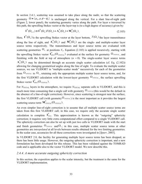
In section 2.4.1, scattering was assumed to take place along the nadir, so that the scatteringgeometry Ω ≡ { μ0 , μ,φ − φ0}is unchanged along the vertical. For a slant line-of-sight path(Figure 2, lower panel), the scattering geometry varies along the path. For layer n traversed bythis path, the upwelling Stokes vector at the layer-top is (to a high degree of accuracy) given by:↑↑↑↑I ( Ωn−1)≅ I ( Ωn) T(Ωn) + Λn( Ωn) + Mn( Ωn) . (2.103)↑Here, I ( Ωn) is the upwelling Stokes vector at the layer bottom, T ( Ωn) the layer transmittance↑along the line of sight, and ( Ω↑Λn n) and Mn( Ω n) are the single- and multiple-scatter layersource terms respectively. The transmittances and layer source terms are evaluated withscattering geometries Ωn at positions V n . Equation (2.103) is applied recursively, starting with↑the upwelling Stokes vector IBOA( ΩNTOTAL)evaluated at the surface for geometry ΩNTOTAL , andfinishing with the field at top of atmosphere (n = 0). The single-scatter layer source terms↑Λn( Ωn) may be determined through an accurate single scatter calculation (cf. Eq. (2.102))allowing for changing geometrical angles along the line of sight. To evaluate the multiple scattersources, we run <strong>VLIDORT</strong> in “multiple-scatter mode” successively for each of the geometriesfrom ΩNTOTAL to Ω1, retaining only the appropriate multiple scatter layer source terms, and, forthe first <strong>VLIDORT</strong> calculation with the lowest-layer geometry ΩNTOTAL , the surface upwelling↑Stokes vector IBOA( Ω NTOTAL).For N TOTAL layers in the atmosphere, we require N TOTAL separate calls to <strong>VLIDORT</strong>, and this ismuch more time consuming that a single call with geometry ΩNTOTAL (this would be the default inthe absence of a line-of-sight correction). However, since scattering is strongest near the surface,the first <strong>VLIDORT</strong> call (with geometryΩNTOTAL ) is the most important as it provides the largest↑scattering source term MNTOTAL( Ω NTOTAL).An even simpler line-of-sight correction is to assume that all multiple scatter source terms aretaken from this first <strong>VLIDORT</strong> call; in this case, we require only the accurate single scattercalculation to complete I↑ TOA. This approximation is known as the “outgoing” sphericitycorrection; it requires very little extra computational effort compared to a single <strong>VLIDORT</strong> call.The sphericity correction can also be set up with just two calls to <strong>VLIDORT</strong> made with the startand finish geometries ΩNTOTAL and Ω1; in this case, multiple scatter source terms at othergeometries are interpolated at all levels between results obtained for the two limiting geometries.In the scalar case, accuracies for all these corrections were investigated in [Spurr, 2003].In <strong>VLIDORT</strong> 2.0, the facility for generating multiple layer source terms has been dropped, asthere has been little usage. However, the outgoing sphericity correction is important, and a newformulation has been developed for this release. This has been validated against the TOMRADcode and is applicable also to the vector <strong>VLIDORT</strong> model. We now describe this.2.4.4. A more accurate outgoing sphericity correctionIn this section, the exposition applies to the scalar intensity, but the treatment is the same for the<strong>VLIDORT</strong> implementation.33
- Page 1: User’s GuideVLIDORTVersion 2.6Rob
- Page 5 and 6: Table of Contents1H1. Introduction
- Page 7 and 8: 1. Introduction to VLIDORT1.1. Hist
- Page 9 and 10: Table 1.1 Major features of LIDORT
- Page 11 and 12: In 2006, R. Spurr was invited to co
- Page 13: corrections, and sphericity correct
- Page 16 and 17: Matrix Π relates scattering and in
- Page 18 and 19: m⎛ P⎞l( μ)0 0 0⎜⎟mmm ⎜ 0
- Page 20 and 21: In the following sections, we suppr
- Page 22 and 23: of the single scatter albedo ω and
- Page 24 and 25: Here T n−1 is the solar beam tran
- Page 26 and 27: ~ + ~ ~ (1)~ ~ + ~ ~ (2)~ ~ − ~ 1
- Page 28 and 29: The solution proceeds first by the
- Page 30 and 31: Linearizations. Derivatives of all
- Page 34 and 35: One of the features of the above ou
- Page 36 and 37: L↑↑ ↑k (cot n −cotn −1)[
- Page 38 and 39: Note the use of the profile-column
- Page 40 and 41: βl,aer(1)(2)fz1e1βl+ ( 1−f ) z2
- Page 42 and 43: For BRDF input, it is necessary for
- Page 44 and 45: streams were used in the half space
- Page 46 and 47: anded tri-diagonal matrix A contain
- Page 48 and 49: in place to aid with the LU-decompo
- Page 50 and 51: In earlier versions of LIDORT and V
- Page 53 and 54: 4. The VLIDORT 2.6 package4.1. Over
- Page 55 and 56: (discrete ordinates), so that dimen
- Page 57 and 58: Table 4.2 Summary of VLIDORT I/O Ty
- Page 59 and 60: Table 4.3. Module files in VLIDORT
- Page 61 and 62: Finally, modules vlidort_ls_correct
- Page 63 and 64: end program main_VLIDORT4.3.2. Conf
- Page 65 and 66: $(VLID_DEF_PATH)/vlidort_sup_brdf_d
- Page 67 and 68: Finally, the command to build the d
- Page 69 and 70: Here, “s” indicates you want to
- Page 71 and 72: The main difference between “vlid
- Page 73 and 74: to both VLIDORT and the given VSLEA
- Page 75 and 76: STATUS_INPUTREAD is equal to 4 (VLI
- Page 77 and 78: 5. ReferencesAnderson, E., Z. Bai,
- Page 79 and 80: Mishchenko, M.I., and L.D. Travis,
- Page 81: Stamnes K., S-C. Tsay, W. Wiscombe,
- Page 84 and 85:
Table A2: Type Structure VLIDORT_Fi
- Page 86 and 87:
DO_WRITE_FOURIER Logical (I) Flag f
- Page 88 and 89:
USER_LEVELS (o) Real*8 (IO) Array o
- Page 90 and 91:
angle s, Stokes parameter S, and di
- Page 92 and 93:
DO_SLEAVE_WFS Logical (IO) Flag for
- Page 94 and 95:
6.1.1.8. VLIDORT linearized outputs
- Page 96 and 97:
NFINELAYERS Integer Number of fine
- Page 98 and 99:
6.1.2.4. VLIDORT linearized modifie
- Page 100 and 101:
The output file contains (for all 3
- Page 102 and 103:
The first call is the baseline calc
- Page 104 and 105:
for a 2-parameter Gamma-function si
- Page 106 and 107:
Remark. In VLIDORT, the BRDF is a 4
- Page 108 and 109:
6.3.3.1. Input and output type stru
- Page 110 and 111:
Table C: Type Structure VBRDF_LinSu
- Page 112 and 113:
Special note regarding Cox-Munk typ
- Page 114 and 115:
squared parameter, so that Jacobian
- Page 116 and 117:
6.4. SLEAVE SupplementHere, the sur
- Page 118 and 119:
is possible to define Jacobians wit
- Page 120 and 121:
etween 0 and 90 degrees.N_USER_OBSG
- Page 122:
6.4.4.2 SLEAVE configuration file c


