CV 601 - Total Hydraulics BV
CV 601 - Total Hydraulics BV
CV 601 - Total Hydraulics BV

You also want an ePaper? Increase the reach of your titles
YUMPU automatically turns print PDFs into web optimized ePapers that Google loves.
Contents<br />
Page 3<br />
General Information<br />
Page 4<br />
Technical data<br />
Page 5<br />
Performance Curves<br />
Page 6-7<br />
Dimensions<br />
Page 8<br />
Relief and Check Valves<br />
Page 9<br />
Spool - Control characteristics<br />
Page 10-11<br />
Spool Controls<br />
Page 12-13<br />
Order Code<br />
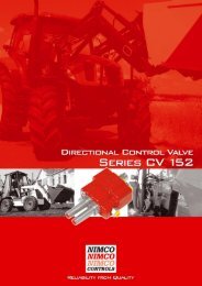
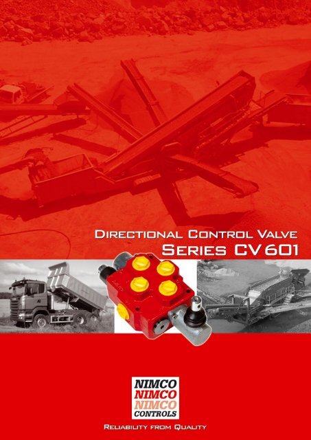
Directional Control Valve 2<br />
Series <strong>CV</strong> <strong>601</strong>
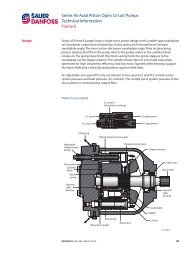
General Information<br />
The <strong>CV</strong> <strong>601</strong> is a robust single spool monoblock valve designed to offer its user very low pressure drops and<br />
with the option of additional spool functions by using a High Pressure Carry-Over Adaptor (Power Beyond).<br />
The valve is designed for a maximum working pressure of 320 bar (4600 psi.) with a flow from 25 to 180<br />
l/min (6.6-48 US GPM).<br />
The <strong>CV</strong> <strong>601</strong> valve offers its user optimised characteristics with regard to function, capacity and quality. It is<br />
designed with the machine builders high demands of cost effectiveness, function and need of exceptionally<br />
good load maneuverbility in mind. Suitable areas of use are dumpers, loaders and other equipment where<br />
precise load control is required.<br />
Although the valves external dimensions are small, it does allow high internal flows and can be equipped<br />
with a large number of accessories as standard. The uniquely designed canal system results in exceptionally<br />
low pressure drops leading to improved performance and longer life not only of the control valve but also<br />
of the other components in the hydraulic system. It can be fitted with two main relief valves to allow for up<br />
to 180 l/min (48 US GPM) flow.<br />
The <strong>CV</strong> <strong>601</strong> is manufactured using the highest quality alloy cast iron which in combination with NIMCO’s<br />
advanced machining and control methods assures the precise accuracy of every component. Each valve<br />
is tested and the results documented prior to despatch.<br />
Minimised spool leakage.<br />
Hard chromium plated spools, low friction and a specially developed honing method gives absolute minimum<br />
spool leakage of the valve.<br />
Easy assembly.<br />
The valve has two pressure inlets and two tank outlets allowing pipes and hoses to be connected either<br />
from the side or top of the valve.<br />
Excellent load control.<br />
The <strong>CV</strong> <strong>601</strong> has load check valves and can be fitted with both standard spools and with specially designed<br />
spools for specific metering needs which will provide optimum control characteristics.<br />
Full utilisation of the spool stroke.<br />
The optimised soft maneuver grooves integrated in each spool and the precise machining of every<br />
component allows the entire stroke of the spool to be used. This allows full control of the load whether the<br />
operator is using very little or full flow capacity. In addition the movement of any spool in any direction will<br />
give the same speed of machine function, enhancing security and reliability.<br />
Uniform and low lever forces.<br />
By combining the unique design features of the valve body and the spools, an excellent balance of the<br />
dynamic forces is achieved throughout the entire pressure and flow range. This keeps spring forces at a<br />
minimum and makes the valve very easy to operate by hand lever as well as when any of the NIMCO’s<br />
remote control valves are used.<br />
Wide range of accessories.<br />
The <strong>CV</strong> <strong>601</strong> offers a wide range spool and remote controls such as single wire controls, pneumatic and<br />
hydraulic proportional or on/off controls are available.<br />
3<br />
Directional Control Valve<br />
Series <strong>CV</strong> <strong>601</strong>
Technical Data<br />
Max Pressure Setting<br />
Main Relief Valve<br />
Tank line<br />
Flow rates<br />
Maximum for the valve<br />
Temperature Range<br />
Standard seals NBR BUNA-N seals<br />
Internal Leakage A(B) to T<br />
100 bar (1450 psi) and 46 mm²/s (cSt)<br />
(117 SSU) viscosity A and B port<br />
bar<br />
320<br />
10<br />
l/min<br />
180<br />
° C<br />
-40 to +80<br />
cm³/min<br />
Max 10<br />
psi<br />
4600<br />
145<br />
US GPM<br />
48<br />
°F<br />
-40 to +176<br />
inch³/min<br />
0.6<br />
Filtration<br />
Contamination level equal to or better then<br />
Viscosity<br />
Recommended operating<br />
Viscosity range<br />
Start viscosity up to<br />
Weight<br />
<strong>CV</strong> <strong>601</strong><br />
18/14 according to ISO 4406<br />
mm²/s<br />
10-400<br />
1000<br />
Kg<br />
7.3<br />
NAS 1638-class 10<br />
cSt<br />
47 - 1875<br />
4687<br />
lbs<br />
16.1<br />
Directional Control Valve 4<br />
Series <strong>CV</strong> <strong>601</strong>
Performance Curves<br />
Pressure Drop PT<br />
Bar 20<br />
10<br />
20 30 40<br />
US gpm<br />
15<br />
220 psi<br />
10<br />
145<br />
5<br />
PT<br />
75<br />
0<br />
30 60 90 120 150 180<br />
Flow L/min<br />
Pressure Drop PA(B)<br />
Bar 20<br />
10<br />
20 30 40<br />
US gpm<br />
15<br />
PA(B)<br />
With check-valve<br />
220 psi<br />
10<br />
145<br />
5<br />
PA(B)<br />
Without<br />
check-valve<br />
75<br />
0<br />
30 60 90 120 150 180<br />
Flow L/min<br />
Pressure Drop A(B)T<br />
Bar 20<br />
10<br />
20 30 40<br />
US gpm<br />
15<br />
220 psi<br />
10<br />
A(B)T<br />
145<br />
5<br />
75<br />
0<br />
30 60 90 120 150 180<br />
Flow L/min<br />
5<br />
Directional Control Valve<br />
Series <strong>CV</strong> <strong>601</strong>
Dimensions<br />
European view setting<br />
Directional Control Valve 6<br />
Series <strong>CV</strong> <strong>601</strong>
Dimensions<br />
US view setting<br />
7<br />
Directional Control Valve<br />
Series <strong>CV</strong> <strong>601</strong>
Relief and Check Valves<br />
One main relief valve. Differential<br />
operated relief valve for the main<br />
circuit. Adjustable from 35 to 320<br />
bar (500-4600 psi).<br />
Part No: 4S-6020<br />
High Flow Option<br />
Double Main Relief Valve Option<br />
Recommended for high flow (over 120 l/min).<br />
Part No: 4S-6020<br />
Part No: 4S-6020<br />
Check valve. Can be used when two or more valves<br />
are connected in series and operates with the same<br />
pressure. The first valve should then be equipped<br />
with a main relief valve RV and the subsequent<br />
valves with <strong>CV</strong>.<br />
Part No: 4S-11362<br />
High Pressure Carry-Over Adaptators (Power Beyond)<br />
are available to serial connect the <strong>CV</strong> <strong>601</strong> with one or<br />
more control valves.<br />
Part No: 4S-1851 (BSP 1″ → ¾″)<br />
Part No: 4S-65251 (UNF 16 → 12)<br />
Part No: 4S-1877 (BSP 1″ → ¾″)<br />
Tank Port Reduction Adaptator can be installed in the<br />
T1 port when the thread size is to be reduced.<br />
Part No: 4S-1891 (BSP 1″ → ¾″)<br />
Part No: 4B-11599 (UNF 16 → 12)<br />
Directional Control Valve 8<br />
Series <strong>CV</strong> <strong>601</strong>
Spool - Control Characteristics<br />
All of NIMCO’s spools are designed for specific flow rates in order to achieve optimal load controls characteristics<br />
and to fully utilise the spools entire stroke. By optimising the balance between spools and valve housing,<br />
spring forces are minimized and exact maneuvering is achieved. Besides the standard spools listed designed<br />
for maximum flow and minimum pressure drop there are also special spools available. For further information<br />
concerning these type of spools please contact your NIMCO representative.<br />
Spool type<br />
Symbol<br />
Order code<br />
Standard spool<br />
Part No.<br />
Double acting<br />
1X<br />
3B-6037<br />
Single acting<br />
A-port<br />
2XA<br />
3B-6111<br />
Single acting<br />
B-port<br />
2XB<br />
3B-6050<br />
Motor<br />
4X<br />
3B-6073<br />
Control Characteristics<br />
P-A(B), Spool S.<br />
Pump flow 70 l/min (19 US Gpm).<br />
Viscosity 25 mm²/s (cSt) (117 SSU)<br />
Oil temp. 50° C (122° F).<br />
1. Pressure in work port 50 bar (725 psi)<br />
2. Pressure in work port 150 bar (2175 psi)<br />
3. Pressure in work port 250 bar (3625 psi)<br />
9<br />
Directional Control Valve<br />
Series <strong>CV</strong> <strong>601</strong>
Spool Controls<br />
Code<br />
Type A-side<br />
B-side Type<br />
Code<br />
9<br />
Spring centered.<br />
(Standard Spool<br />
Control)<br />
Hand lever<br />
vertical.<br />
Link connection.<br />
S1<br />
9M<br />
10<br />
Marine version.<br />
Detent in position<br />
1, 2 and 3<br />
Hand lever<br />
vertical, opposite<br />
direction.<br />
Link connection.<br />
Other length and hand<br />
knobs upon request.<br />
S7<br />
10M<br />
9S<br />
Marine version<br />
Spring centered<br />
with straight<br />
through spool<br />
Hand lever<br />
horizontal.<br />
Link connection.<br />
S2<br />
10S<br />
Detent in position<br />
1, 2, 3 and<br />
straight through<br />
spool.<br />
Hand lever vertical.<br />
Encased.<br />
(Standard Spool<br />
Control)<br />
S5<br />
13<br />
Spring centered.<br />
Detent in position 2.<br />
14<br />
Spring centered.<br />
Detent in position 3.<br />
Hand lever<br />
vertical encased.<br />
Marine version<br />
in combination<br />
with 9M and<br />
10 M only.<br />
S5M<br />
Directional Control Valve 10<br />
Series <strong>CV</strong> <strong>601</strong>
Spool Controls<br />
Code<br />
Type A-side<br />
B-side Type<br />
Code<br />
P<br />
PP<br />
Pneumatic on/off.<br />
Pneumatic<br />
proportional.<br />
H<br />
Hydraulic on/off.<br />
Pilot pressure<br />
6-15 bar<br />
87-217 psi.<br />
Wire control for<br />
3-position spool.<br />
HP<br />
Hydraulic<br />
proportional.<br />
Pilot pressure<br />
6-15 bar<br />
87-217 psi.<br />
3W<br />
EP<br />
Electro-pneumatic<br />
on/off.<br />
12v/270mA alt.<br />
24v/150mA.<br />
Hirschmann contact<br />
is standard.<br />
Others are available<br />
on request.<br />
HD<br />
HPD<br />
Hydraulic on/off.<br />
Pilot pressure<br />
6-15 bar<br />
87-217 psi.<br />
Hydraulic<br />
proportional.<br />
Pilot pressure<br />
6-15 bar<br />
87-217 psi.<br />
HD and HPD<br />
cannot be<br />
combined with<br />
any other spool<br />
controls.<br />
HD<br />
HPD<br />
11<br />
Directional Control Valve<br />
Series <strong>CV</strong> <strong>601</strong>
Order Code<br />
Example 1<br />
This Directional Control Valve is equipped with one Main Relief Valve (code<br />
RV 150), a double acting spool (code 1X) with a spring centered spool control<br />
(code 9) and an enclosed type hand lever control (code S5)<br />
High Pressure Carry-Over Adaptor installed in the T1 port.<br />
Directional Control Valve 12<br />
Series <strong>CV</strong> <strong>601</strong>
Order Code<br />
Copy this page and use as<br />
your technical order form.<br />
Standard Main Pressure<br />
Setting is done at 70 lpm<br />
(16 US GPM). Please<br />
clairly indicate if you want<br />
the MRV pressure to be<br />
set at another flow.<br />
<strong>CV</strong> <strong>601</strong><br />
Main relief valve<br />
RV + pressure setting<br />
or<br />
Check Valve <strong>CV</strong><br />
Optional 2nd<br />
Main relief valve<br />
if flow is over 120 l/min<br />
RV + pressure setting<br />
if not applicable mark X<br />
Pump inlet side P1<br />
top P2<br />
Spool type code page 8<br />
MRV<br />
P2<br />
A T2<br />
P1<br />
Section 1<br />
T1<br />
B<br />
2nd MRV Optional<br />
BSP G<br />
SAE S<br />
Metric M<br />
Tank port side T1<br />
top T2<br />
High Pressure Carry-Over<br />
(Power Beyond) S<br />
Thread Reducing<br />
Adaptor R<br />
Spool control B-side code page 9-10<br />
Spool control A-side code page 9-10<br />
13<br />
Directional Control Valve<br />
Series <strong>CV</strong> <strong>601</strong>