simocode-dp - Auser
simocode-dp - Auser
simocode-dp - Auser
You also want an ePaper? Increase the reach of your titles
YUMPU automatically turns print PDFs into web optimized ePapers that Google loves.
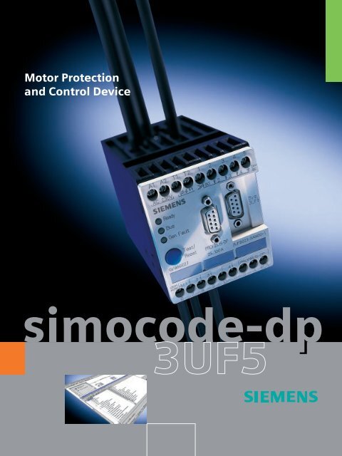
Motor Protection<br />
and Control Device<br />
<strong>simocode</strong>-<strong>dp</strong>
Contents<br />
Page<br />
The 3UF5 SIMOCODE-DP System 3<br />
Thermistor-Type Motor Protection<br />
Without Compromise 4<br />
Wide Scope of Control Functions 5<br />
Extensive Diagnostics 7<br />
Communication – PROFIBUS-DP 8<br />
Simple Start-Up 10<br />
Price Advantage with SIMOCODE-DP 12<br />
Modular Device Configuration 14<br />
SIVACON –<br />
The Communications-Capable<br />
Low-Voltage Switchgear 16<br />
Technical Specifications 17<br />
2
The 3UF5 SIMOCODE-DP System<br />
There is less and less time in between<br />
ordering and the start-up of<br />
a system – however, the requirements<br />
made on motor feeders are<br />
increasing. A system should, for<br />
example, be compact, intelligent<br />
and powerful. Every motor has<br />
optimum protection, the scope of<br />
wiring is as small as possible and<br />
spares must not mean high storage<br />
costs.<br />
To meet all these requirements, the<br />
system designer has to have extensive<br />
knowledge of the complete range of<br />
low-voltage switchgear. The new communications-capable<br />
SIMOCODE®-DP<br />
3UF5 – Siemens Motor Protection<br />
and Control Device - Decentralized<br />
Peripherals – makes life easier for the<br />
system designer.<br />
SIMOCODE-DP is a tried and tested<br />
system<br />
Increasingly, the communicationscapable<br />
SIMOCODE-DP 3UF5 motor<br />
protection and control device is being<br />
successfully used worldwide in lowvoltage<br />
switchgear systems.<br />
It represents the intelligent link<br />
between the motor feeder and the<br />
process control system.<br />
The fact that this state-of-the-art<br />
technology is being increasingly used<br />
reflects the requirement for increased<br />
plant availability but at the same time,<br />
cost savings during the construction<br />
and commissioning of a plant and its<br />
operation. This places a wide range of<br />
requirements on such an intelligent<br />
field device.<br />
As it is widely used in the process and<br />
others industries, you can find it all over<br />
the world. The system SIMOCODE-DP<br />
protects and controls load feeders for<br />
instance in the paper, chemical, textile,<br />
steel, oil and gas, waterwork plants,<br />
cement, petrochemical, shipbuilding,<br />
food and consumer goods industries.<br />
There it has proved its reliability for<br />
more than five years.<br />
Intelligent load feeders<br />
SIMOCODE-DP also helps ensure that<br />
high-availability systems such as coal,<br />
gas and hydroelectric plants run<br />
around the clock. SIMOCODE also<br />
provides the communication between<br />
the master level and the automation<br />
level by its integrated PROFIBUS-DP<br />
interface.<br />
In all that industries it is used for an<br />
enormous variety of applications.<br />
SIMOCODE-DP is capable to realize<br />
several control functions, like direct-,<br />
reversing-, star-delta starters and to<br />
implement user-specific controls by<br />
using the freely assignable inputs and<br />
outputs and the built-in truth tables,<br />
timers and counters. The existing<br />
motor protection functions (overload,<br />
phase failure and current imbalance<br />
detection) are supplemented by<br />
thermistor motor protection and earthfault<br />
monitoring.<br />
Supervisory level<br />
Master computer<br />
Control level<br />
Automation level<br />
ETHERNET<br />
PROFIBUS-DP<br />
PLC e.g.<br />
SIMATIC<br />
K1 K2 K3<br />
K4<br />
Communicationscapable<br />
low-voltage<br />
switchgear<br />
SIMOCODE-DP<br />
Motor<br />
Motor<br />
Motor<br />
Field level<br />
Fans<br />
Conveyor<br />
belt<br />
Fans<br />
3
Thermistor-Type Motor Protection<br />
Without Compromise<br />
Electrical equipment such as AC<br />
motors and transformers need<br />
protection against excessive heating.<br />
Unbalanced current consumption,<br />
phase failure or a stalled rotor are<br />
some of the possible causes of<br />
overloading.<br />
Overload protection<br />
SIMOCODE-DP protects the load,<br />
independent of the automation level,<br />
against overload, phase failure and<br />
current imbalance. The 3UF50 basic<br />
unit can also be used as an<br />
autonomous, solid-state overload relay<br />
for motor protection.<br />
Finely adjustable adaptation to<br />
start-up conditions<br />
It is possible to select a tripping class<br />
in six steps from CLASS 5 to CLASS<br />
30. The tripping time can be finely<br />
adjusted to the start-up conditions –<br />
and the utilization of the motors can<br />
be optimized.<br />
Built-in thermistor motor protection<br />
Thermistor motor protection is used for<br />
the thermal protection of motors. The<br />
temperature is measured directly at<br />
the motor windings via a PTC or NTC<br />
thermistor detector and is evaluated by<br />
SIMOCODE-DP.␣ No additional<br />
evaluation devices are required, thus<br />
saving space in the switchboard.<br />
Apart from binary thermistor detectors,<br />
SIMOCODE-DP also evaluates<br />
analogous (KTY) thermistor detectors.<br />
KTY detectors incorporate a resistance<br />
curve which rises linearly with the<br />
temperature. Therefore, a warning and<br />
a tripping threshold can be set in the<br />
SIMOCODE-DP.<br />
A considerable advantage.<br />
For motors with a thermally critical<br />
rotor, e.g. slipring and squirrel-cage<br />
motors with increased power, the combination<br />
of thermistor-type motor protection<br />
and electronically delayed overload<br />
relay offers full thermal protection –<br />
thermistor-type motor protection.<br />
Earth fault monitoring<br />
always available<br />
This protective function is also offered<br />
by the SIMOCODE-DP communications-capable<br />
motor protection and<br />
control device. The internal earth fault<br />
detection can be activated in addition<br />
to the thermistor evaluation.<br />
4<br />
For motors with 3-wire connection,<br />
fault currents which exceed the<br />
current setting I e (during nominal<br />
operation) by 30% can be detected<br />
with the internal earth fault detection.<br />
The SIMOCODE-DP system is also<br />
suitable for a precise earth fault<br />
detection. A version is available with<br />
external earth fault detection. By<br />
connecting an external summation<br />
current transformer, fault currents of<br />
0.3 A, 0.5 A and 1 A can be detected<br />
for both 3- and 4-wire motors.<br />
An additional evaluation device is not<br />
required, and the space requirement in<br />
the cubicle is further reduced.<br />
Protection against stalled rotors<br />
Protection against the stalling of<br />
motors during normal operation is<br />
achieved by a comparison of a settable<br />
current limit.<br />
Resettable everywhere – manual,<br />
remote and automatic reset<br />
A reset at the device is implemented<br />
with the Test/Reset button. By connecting<br />
a pushbutton to the inputs, via<br />
PROFIBUS-DP or via the Test/Reset<br />
button at the operating module, a<br />
remote reset can be implemented. An<br />
automatic reset can also be<br />
configured.<br />
Reduction of variants by large<br />
setting ranges: 0.25 A – 820 A<br />
A current window from 0.25 A to<br />
820 A is covered using only six units.<br />
This reduces product selection – and<br />
saves on spares costs.<br />
Tripping characteristics for 3-pole load<br />
Tripping time min<br />
s<br />
120<br />
100<br />
50<br />
20<br />
10<br />
5<br />
2<br />
1<br />
50<br />
20<br />
10<br />
5<br />
2<br />
15<br />
10<br />
Class 5<br />
Class 30<br />
25<br />
20<br />
0.6 1 2 5 10x I e<br />
Tripping current (mean values)<br />
Tolerance < ± 10%<br />
With a tolerance of less than 10%,<br />
SIMOCODE-DP has an accurate<br />
tripping curve which guarantees an<br />
optimum utilization of motors.<br />
Long-term stability also contributes to<br />
the high degree of accuracy.<br />
Cost reduction by built-in current<br />
transformers<br />
Current detection is achieved via three<br />
current transformers which are<br />
integrated in the device. This means that<br />
savings are made three ways – i.e.<br />
space, wiring and additional device<br />
requirements.<br />
Easy ‘through feed ‘connection<br />
Feeder cables up to 100 A rating can be<br />
easily connected to the 3UF50. The<br />
cables are not terminated to the device,<br />
but are fed through 3 integral conduits<br />
in the device housing – a major saving<br />
in installation time.<br />
Protection of motors in the EExe range<br />
The SIMOCODE-DP system complies<br />
to the regulations for overload<br />
protection of explosion-protected<br />
motors of the “increased safety“ type<br />
EExe DIN EN 50019/ DIN VDE0165,<br />
DIN VDE 0170/0171 and to the test<br />
regulations of the Federal Institute for<br />
Physics and Technology and the test<br />
requirements of the Federal Institute<br />
for Physics and Technology No. 3.53-<br />
14605/96.<br />
Tripping characteristics for 2-pole load<br />
min<br />
Tripping time<br />
s<br />
120<br />
100<br />
50<br />
20<br />
10<br />
5<br />
2<br />
1<br />
50<br />
20<br />
10<br />
5<br />
2<br />
15<br />
10<br />
Class 5<br />
Class 30<br />
25<br />
20<br />
0.6 1 2 5 10x I e<br />
Tripping current (mean values)
Wide Scope of Control Functions<br />
With the SIMOCODE-DP system, nine<br />
different control functions can be<br />
implemented:<br />
• Overload relay<br />
• Direct starter<br />
• Reversing starter<br />
• Star-delta starter<br />
• Dahlander<br />
• Pole-changing switch<br />
• Slide valve (encoder)<br />
• Solenoid valve<br />
• SIKOSTART® 3RW22<br />
(soft starter)<br />
In addition, permanent or nonmaintained<br />
command mode can be<br />
set. All control functions can be<br />
implemented using the 3UF50 basic<br />
unit. If more than four inputs and four<br />
outputs are required, an additional<br />
eight inputs and four outputs can be<br />
fitted by using an extension module.<br />
Cost reduction by pre-defined<br />
control functions<br />
In the SIMOCODE-DP, all necessary<br />
interlocking requirements for the<br />
relevant control function (e.g. with<br />
encoders the undelayed deactivation<br />
of the motor in case of an operation of<br />
the limit or torque switch) are implemented.<br />
This offers major advantages:<br />
• Reducing the demands put on the<br />
user program in the programmable<br />
controller, i.e. fast planning, fewer<br />
possibilities for errors, shorter<br />
program cycle times<br />
• Time-critical functions of the<br />
motor feeder are independent of<br />
the signal process time in the<br />
automation level and of the<br />
communication system.<br />
In addition, run time checks can be set<br />
for the start or stop of motors and for<br />
the slide valve control functions in<br />
between the limits.<br />
Safety by operator enable and<br />
manual/automatic switch-over<br />
In the automatic mode, control<br />
commands (e.g. ON, OFF) are transmitted<br />
to SIMOCODE-DP via the bus.<br />
Control commands from the switchgear<br />
cubicle (e.g. of the operating<br />
module) or from the local control<br />
station are only possible in this<br />
operating mode if the corresponding<br />
operator enable commands have been<br />
set.<br />
3/N/PE~ 50/60 Hz 400/230 V<br />
L1<br />
L2<br />
L3<br />
NPE<br />
Q1<br />
1L1<br />
2L1<br />
1N<br />
2N<br />
F11<br />
Q1<br />
RMT<br />
l ><br />
2<br />
3<br />
-K1 -K2<br />
-K3<br />
Overload<br />
Current imbalance<br />
Phase failure<br />
Thermistor<br />
Earth fault<br />
Blocking protection<br />
Current value detection<br />
1<br />
A1A2 T1T2 1 2 3 4 5<br />
230 V AC<br />
3UF50<br />
PROFIBUS-DP<br />
6 7 8 9 10 11 B A SPE/PE<br />
Ready<br />
Gen. Fault<br />
Test/<br />
Reset<br />
Switching at the<br />
cubicle door via<br />
the 3UF52<br />
operating module<br />
ON<br />
OFF<br />
2<br />
3<br />
ON<br />
OFF<br />
Local<br />
1<br />
1U 1V 1W<br />
M<br />
3~<br />
2W<br />
2U<br />
2V<br />
-K1 -K2<br />
-K3<br />
5
If the automatic level switches to<br />
manual operation, or if local control is<br />
activated by means of a local manual/<br />
automatic key switch, the bus control<br />
commands are ignored and the feeder<br />
can now be exclusively controlled via<br />
the operating module or using the local<br />
control station.<br />
Reduction of failure times by<br />
autonomous operation<br />
In case of system failures on the<br />
communication system, SIMOCODE-<br />
DP automatically switches to manual<br />
mode.<br />
When this occurs, the load is either<br />
switched OFF or the operating state is<br />
maintained. Further control is possible<br />
using the manual mode.<br />
Downtimes in case of failures in the<br />
automation and communication level<br />
are considerably reduced: The process<br />
can still be safely continued locally due<br />
to the autonomous structure of the<br />
SIMOCODE-DP.<br />
The process can be resumed however<br />
surely by the self-sufficient structure of<br />
the system SIMOCODE-DP locally.<br />
Self-sufficient means that all<br />
protective relays for motor and control<br />
functions are processed independently<br />
of the automation level in the<br />
SIMOCODE-DP.<br />
Flexibility due to decentralized<br />
signal logic, delays and<br />
conditioning<br />
The great flexibility of the SIMOCODE-<br />
DP system is especially characterized<br />
by the integrated:<br />
• 3 truth tables<br />
(3 inputs with 1 output each)<br />
• 1 truth table<br />
(5 inputs with 2 outputs)<br />
• 2 timers<br />
(0.5 s...60 min; output behaviour:<br />
ON delay, OFF delay, fleeting<br />
NO contact)<br />
• 2 counters<br />
(0...65535)<br />
• 4 elements of signal processing<br />
– Inverted level without memory<br />
– Rising edge with memory<br />
– Falling edge with memory<br />
• Signal conditioning<br />
– 3 flashing modules<br />
– 3 flickering modules<br />
• 2 elements of non-resetting<br />
on-voltage failure<br />
The inputs and outputs of the system<br />
can be assigned to predefined control<br />
functions as well as to the truth tables,<br />
timers and counters. Thus, a flexible<br />
use of the predefined control functions<br />
is possible.<br />
The make/break contact behaviour of<br />
the outputs is set by the signal<br />
processing modules.<br />
Selective start of the system<br />
After a mains failure, the motor feeders<br />
can be restarted using time-grading.<br />
This makes a fast and selective start of<br />
the system possible.<br />
6<br />
Control and signalling
Extensive Diagnostics<br />
SIMOCODE-DP offers a large amount<br />
of operational and statistical data on<br />
the feeder, which is available to the<br />
user for visualization and diagnostic<br />
purposes.<br />
This data can be accessed:<br />
• directly at the switchboard via the<br />
LED display of the hand-held unit<br />
plugged into the basic unit or<br />
operator panel, or via a PC with<br />
Win-SIMOCODE-DP/Smart.<br />
• via PROFIBUS-DP. The data can be<br />
read by the user program and it can<br />
be transferred to a corresponding<br />
operator communication and<br />
monitoring system. Thus, the various<br />
operational and statistical information<br />
can be displayed in the control room.<br />
• over PROFIBUS-DPV1 with a<br />
communications processor which<br />
were in the PC/PU and the software<br />
Win-SIMOCODE-DP/Professional.<br />
Always informed as to the current<br />
operating state<br />
SIMOCODE-DP continuously informs<br />
the process engineer about the current<br />
operating state:<br />
• actual phase current in %<br />
• ON/OFF<br />
• Anti-clockwise, clockwise LEFT/<br />
RIGHT<br />
• Fast, slow<br />
• Slide open, closed, moving<br />
• Warning<br />
• Fault<br />
Reduction of failures by the<br />
signalling of critical operating<br />
states<br />
The settable current limits inform the<br />
process engineer about critical states<br />
in the system. For example, a current<br />
which is below the lower current limit<br />
setting could mean a broken conveyor<br />
belt for example. The overloading of a<br />
mixing machine for example can be<br />
quickly detected by the display of<br />
‘upper current limit exceeded.’ To avoid<br />
an overload trip of the machine, the<br />
process engineer can take precise<br />
steps to change the working process,<br />
such as reducing the amount of<br />
material in the mixer.<br />
Display of other critical operating<br />
states:<br />
• Current imbalance<br />
• Overload warning/trip<br />
• Thermistor motor protection<br />
warning/trip<br />
• Earth fault warning/trip<br />
• Locked rotor protection<br />
• Warning/trip upper/lower current<br />
limit response<br />
Reduction of maintenance times<br />
Maintenance intervals can be<br />
increased, as all statistical data relating<br />
to the condition of a particular feeder is<br />
transmitted from the SIMOCODE-DP to<br />
the PLC. SIMOCODE-DP registers the<br />
number of starts and the number of<br />
overload trips, counts the operating<br />
hours and calculates the current in %<br />
of the last trip. All data is stored in a<br />
non-volatile memory in SIMOCODE-DP.<br />
Analog current display<br />
For display of analog current value<br />
through a display device on the panel<br />
door; the SIMOCODE-DP system is<br />
provided with an external current<br />
transformer (range 0.25 A–820 A/1A).<br />
With this it is also possible for the<br />
system selector to inform about the<br />
actual current flowing in the motor<br />
feeder.<br />
Self-monitoring<br />
The correct function of the<br />
SIMOCODE-DP processor is<br />
permanently monitored. If a fault<br />
occurs, SIMOCODE-DP switches the<br />
load into the safe condition which was<br />
previously parameterized (OFF or the<br />
operating status is maintained -<br />
monostable or bistable behaviour).<br />
Also testable ‘in action’<br />
This function gives SIMOCODE-DP<br />
additional safety and better monitoring<br />
features.<br />
The operation of SIMOCODE-DP can<br />
be checked during running – without<br />
switching off of the motor. This saves<br />
time and avoids unnecessary<br />
interruptions of the operation.<br />
Display and diagnoses with Win-SIMOCODE-DP software<br />
7
Communication –<br />
PROFIBUS-DP<br />
PC or PU with<br />
Win-SIMOCODE-DP/<br />
Professional<br />
PLC<br />
MMI<br />
with PROFIBUS-DPcommunication<br />
processor<br />
PC or PU<br />
PROFIBUS-DPV1<br />
Online parameterization,<br />
diagnostics, control<br />
and test via acyclical<br />
reading and writing<br />
of data<br />
PROFIBUS-DP<br />
Cyclical exchange of data of control and<br />
signal data. Moreover exchange of diagnostics<br />
by changing and parameterization at communication<br />
processor running-up<br />
PC or PU with<br />
Win-SIMOCODE-DP/Smart<br />
PLC Programmable<br />
Logic Controller<br />
MMI Man-Machine<br />
Interface<br />
PU/PC Programming Unit/<br />
Personal Computer<br />
3UF50 SIMOCODE-DP<br />
SIMOCODE-DP SIMOCODE-DP SIMOCODE-DP<br />
From point to point,<br />
parameterization, diagnostics,<br />
control SIMOCODE-DP and<br />
test via RS-232 interface<br />
PROFIBUS-DP (Process Fieldbus -<br />
Decentralized Peripherals) provides<br />
high-performance communication<br />
between the SIMOCODE-DP and the<br />
automation level. Control commands,<br />
operational data, statistical data and<br />
parameter data are transmitted via the<br />
two-wire bus cable. There is also the<br />
possibility to use optical link modules<br />
so that the data transmission would be<br />
effected via plastic or glass fibre optic<br />
cables.<br />
Here, the communications processor<br />
(CP/IM) plugged into the programmable<br />
logic controller (PLC) provides the<br />
management of the SIMOCODE-DP<br />
Technical specifications PROFIBUS-DP<br />
Total stations<br />
Transmission medium<br />
Max. distance<br />
devices connected to the bus and<br />
forms the interface to the user<br />
program. Further processing of the<br />
SIMOCODE-DP data, i.e. the integration<br />
into the supervisory control<br />
system and any subsequent<br />
processing is handled by the user<br />
program.<br />
Short transmission times<br />
To achieve short transmission times,<br />
PROFIBUS-DP features several data<br />
channels. Up to 12 bytes can be sent<br />
cyclically from SIMOCODE-DP<br />
to the automation level and up to<br />
4 bytes can be returned.<br />
30 SIMOCODE-DP per segment;<br />
with RS485 repeaters 122 SIMOCODE-DP<br />
shielded, twisted pair cable or plastic fibre<br />
or glass fibre optic cable<br />
9.6 km for two-wire, 100 km for glass fibre<br />
optic cable, 425 m for plastic fibre optic cable<br />
The diagnostic data of 20 bytes is<br />
only sent to the automation level of<br />
SIMOCODE-DP in case of a change,<br />
i.e. the diagnostic channel is eventcontrolled.<br />
213 bytes of parameter<br />
data are only sent to the SIMOCODE-<br />
DP during the start-up of the<br />
automation system.<br />
Communication –<br />
PROFIBUS-DPV1<br />
The PROFIBUS-DP standard has been<br />
extended by acyclic reading and writing<br />
of data and is named PROFIBUS-DPV1.<br />
Acyclic reading and writing means for<br />
SIMOCODE-DP that from a central<br />
workstation over PROFIBUS-DPV1<br />
with a PC or PU fitted with communications<br />
processor and the software<br />
Win-SIMOCODE-DP/Professional all<br />
control, diagnosis, test and parameter<br />
data can be read and written. The<br />
PROFIBUS-DPV1 is a secondary<br />
protocol for the PROFIBUS-DP, and it<br />
does notrequire additional lines or<br />
interfaces.<br />
Transmission medium<br />
Transmission speed<br />
PROFIBUS-DP (EN 50170), PROFIBUS-DPV1<br />
9.6, 45.45, 93.75, 187.5, 500, 1500 kBit/s<br />
8
See for yourself. You can<br />
get information on the highperformance<br />
PROFIBUS<br />
simply via the Internet. This<br />
will give you an immediate<br />
overview over the technology<br />
and all relevant products<br />
The communication processors<br />
SIMOCODE-DP can work with any<br />
standard DP master which is able to<br />
read GSD files and which is capable<br />
of processing the following amounts<br />
of data:<br />
• Control data 1 or 4 byte cyclic from<br />
the DP master to SIMOCODE-DP<br />
• Signalling data 1/4/12 byte cyclic<br />
from SIMOCODE-DP to the DP<br />
master<br />
• Diagnosis data 20 byte acyclic from<br />
SIMOCODE-DP to the DP master<br />
• Parameter data 213 byte<br />
For acyclic reading and writing of<br />
data, the communication processor<br />
must operate with the standard<br />
extension PROFIBUS-DPV1.<br />
Bus system expandable<br />
If no bus system is applicable at the<br />
today‘s point in time, this then can be<br />
easily re-tooled later. That‘s because<br />
SIMOCODE-DP processes all protective<br />
relays for motor and control<br />
functions independently of the<br />
automation level.<br />
Of course, SIMOCODE-DP is also<br />
generally applicable as self-sufficient<br />
protective relay for motor and<br />
controller without PROFIBUS-DP.<br />
Siemens together with<br />
more than 1,100 other<br />
members around the world<br />
makes PROFIBUS International<br />
(PI) the world’s<br />
largest organization for<br />
industrial communication.<br />
The local representation<br />
with regional PROFIBUS<br />
Associations (RPA) in 23<br />
countries ensures worldwide<br />
PROFIBUS support.<br />
SIMOCODE-DP is listed as<br />
a full compatible and certified<br />
PROFIBUS device. This<br />
ensures that the communications-capable<br />
devise fully<br />
supports the EN 50170<br />
PROFIBUS standard.<br />
9
Simple Start-Up<br />
PC or PU with<br />
Win-SIMOCODE-DP/<br />
Professional<br />
PLC<br />
MMI<br />
with PROFIBUS-DP<br />
Communication<br />
Processor<br />
PROFIBUS-DPV1<br />
Online Parameterization<br />
PROFIBUS-DP<br />
Transmission of device<br />
parameters during<br />
system start-up<br />
PC or PU with<br />
Win-SIMOCODE-DP/Smart<br />
SIMOCODE-DP SIMOCODE-DP SIMOCODE-DP<br />
Point-to-point parameterization<br />
over SIMOCODE-DP system<br />
interface<br />
Possibilities of parameterization<br />
Integrating many slaves using only<br />
one software<br />
The integration of SIMOCODE-DP as a<br />
DP slave within SIMATIC S7 is as easy<br />
as possible. Configuration and<br />
parameterization of the whole<br />
hardware including PROFIBUS-DP<br />
network and all PROFIBUS-DP slaves<br />
is handled by the SIMATIC Manager.<br />
No matter whether you work with<br />
central or decentral periphery devices,<br />
whether you have only SIMOCODE-DP<br />
or also other DP slaves – everything is<br />
handled by one software.<br />
SIMOCODE-DP – online<br />
parameterization<br />
Now the user is able to parameterize<br />
his SIMOCODE-DP “online“ from a<br />
central location by using the<br />
PROFIBUS-DP.<br />
So, what is meant by “online“?<br />
Up to now it was only possible to<br />
transmit device parameters from the<br />
DP master to the DP slave during the<br />
system start-up. From now on it´s also<br />
possible to read and write those<br />
afterwards. Access is now available not<br />
only for the cyclic transmitted input<br />
and output data but also to a number<br />
of SIMOCODE-DP data sets<br />
additionally to the device parameters.<br />
This means that based on a central<br />
development and diagnostic<br />
workstation with our new Win-<br />
SIMOCODE-DP/Professional software<br />
you are now able to parameterize,<br />
observe, control and test via the<br />
PROFIBUS-DP.<br />
This workstation should be equipped<br />
with a personal computer (PC) or a<br />
programming unit (PU) having an<br />
interface for PROFIBUS-DP (e.g.<br />
CP5611, CP5613). If a Siemens PU is<br />
used, the required PROFIBUS-DP<br />
interface is already integrated.<br />
Reduced commissioning time<br />
It’s no longer required to run from<br />
switchroom to switchroom to<br />
parameterize motor feeders. Based on<br />
a central workstation, all of the<br />
PROFIBUS-DP-connected<br />
SIMOCODE-DPs can be parameterized<br />
after the bus parameter has once been<br />
set correctly.<br />
Increased system availability<br />
In the past, changing of parameters<br />
often meant an interruption of program<br />
processing in the programmable logic<br />
controller (PLC) – meaning a full stop<br />
of the whole system.<br />
By using WinSIMOCODE-DP/Professional,<br />
you can transmit SIMOCODE-DP<br />
parameters directly via PROFIBUS-DP<br />
to each single unit – without stopping<br />
program processing in the PLC.<br />
10
”Totally Integrated” in SIMATIC S7 –<br />
with OM SIMOCODE-DP<br />
Win-SIMOCODE-DP/Professional is<br />
“totally integrated“ in SIMATIC S7.<br />
Is your application focusing on a central<br />
data management for programs<br />
and parameters, the object manager<br />
(OM SIMOCODE-DP) integrates<br />
SIMOCODE-DP/Professional into<br />
STEP7 HW-Config – allowing you to<br />
parameterize your SIMOCODE-DP<br />
from there.<br />
Therefore, you have got the unique<br />
possibility of parameterizing all units<br />
with the same software<br />
Win-SIMOCODE-DP/Professional<br />
regardless whether the parameters are<br />
stored in a central PLC or are loaded<br />
singly into each device.<br />
Totally Integrated in SIMATIC S7<br />
A plus for commissioning<br />
Another advantage of the SIMOCODE-DP<br />
system is that a motor feeder can be<br />
tested during the commissioning stage<br />
with the Win-SIMOCODE-DP/Professional<br />
software. This means, there lies a<br />
possibility that one can switch on and off<br />
from a central workstation and also set<br />
the testbits and enquire about the device<br />
state.<br />
Interconnectivity from SIMOCODE-DP to a PROFIBUS-DP network<br />
Parameterization with Win-SIMOCODE-DP/Professional<br />
11
Price Advantage with SIMOCODE-DP<br />
Figure 1 shows the configuration of a<br />
typical communications-capable motor<br />
feeder with overload relay, thermistor<br />
motor protection device, earth fault<br />
detection, current value transmission<br />
via A/D converters and a decentralized<br />
peripheral system for the bus<br />
connection.<br />
Figure 2 and Figure 3 show the motor<br />
branch of the future.<br />
Reduced number of products<br />
cover the entire range<br />
For the complete control and<br />
monitoring including connection to the<br />
PROFIBUS-DP, only SIMOCODE-DP is<br />
required. This means that no additional<br />
overload relays, thermistor evaluation<br />
devices etc. need to be installed.<br />
Reduction of the scope of wiring<br />
between field and control level<br />
Communication between the field<br />
level and the higher automation level<br />
(PLC or process control system DCS)<br />
is normally implemented via coupling<br />
devices and point-to-point connections<br />
to input and output modules of the<br />
PLC or DCS. With the application of<br />
SIMOCODE-DP, the scope of wiring is<br />
reduced to a minimum – a two-wire<br />
PROFIBUS-DP cable for up to 100<br />
motor feeders; coupling devices and<br />
input/output modules, cable gallery are<br />
not required.<br />
Reduction in wiring costs in<br />
the field level<br />
In the case of the reverser starter<br />
(figure 3), no electrical interlocking is<br />
required, and no time-delay relay which<br />
prevents a direct switch-over from<br />
clockwise to anti-clockwise rotation is<br />
necessary. Everything is implemented<br />
with SIMOCODE-DP.␣ The only thing<br />
required is to set the desired switchover<br />
delay time.<br />
Without 3UF5<br />
With 3UF5<br />
-Q1<br />
-K1<br />
3UL22<br />
-K2<br />
Earth fault<br />
detection<br />
3UL21<br />
Current value<br />
transmission<br />
–<br />
4...20 mA<br />
–<br />
-Q1<br />
-K1 -K2<br />
Overload<br />
Current imbalance<br />
Phase failure<br />
Earth fault protection<br />
Thermistor<br />
Blocking protection<br />
Current value detection<br />
Overload relay<br />
3RU50<br />
PROFIBUS-DP<br />
Figure 1: Well-tried technology<br />
12<br />
3UN21<br />
Thermistor<br />
motor protection<br />
M<br />
3~<br />
DI AI DO<br />
Decentralized peripherals<br />
M<br />
3~<br />
Figure 2: Motor branch of the future
L1<br />
L2<br />
L3<br />
N<br />
PE<br />
3/N/PE~ 50/60 Hz<br />
400/230 V<br />
Q1<br />
1L1<br />
1N<br />
2L1<br />
2N<br />
F11<br />
Q1<br />
RMT<br />
-K1 -K2<br />
1<br />
2<br />
4<br />
l ><br />
2<br />
4<br />
Overload<br />
Current unbalance<br />
Phase failure<br />
Thermistor<br />
Earth fault<br />
Blocking protection<br />
Current value detection<br />
A1 A2 T1T2 1 2 3 4 5<br />
230 V AC<br />
3UF50<br />
PROFIBUS-DP<br />
6 7 8 9 10 11 B A SPE/PE<br />
Ready<br />
Gen. Fault<br />
Test/<br />
Reset<br />
Anti-clockwise<br />
Clockwise<br />
Off<br />
Local<br />
M<br />
3~<br />
-1<br />
-K1 -K2<br />
Figure 3: Reversing starter with SIMOCODE-DP<br />
As all functions are integrated into one<br />
device, the following savings are<br />
possible.<br />
Savings possible:<br />
device variants in<br />
the motor feeders<br />
space requirement<br />
in the cubicle<br />
the wiring cost<br />
between control level<br />
and field level<br />
scope of wiring<br />
in the unit control<br />
level<br />
start-up<br />
times<br />
spares<br />
costs<br />
13
Modular Device Configuration<br />
The modular configuration of the<br />
SIMOCODE-DP system means that it<br />
can be used as a protection and<br />
control device for feeders. The system<br />
consists of the following components:<br />
3UF50 basic unit<br />
The basic unit with four inputs and<br />
four outputs implements all protection<br />
and control functions autonomously,<br />
and provides connection to the<br />
PROFIBUS-DP.␣ The four inputs are fed<br />
by the internal 24 V DC power supply.<br />
The extension module, the operating<br />
module, the manual operating device<br />
or the PC can be connected via the<br />
system interface. The basic unit is<br />
produced with three different control<br />
supply voltages<br />
(24 V DC, 115 V AC, 230 V AC).<br />
Win-SIMOCODE-DP<br />
Runs on any AT-compatible PC under<br />
Windows 95/98/ME/2000 or Windows<br />
NT 4.x. For start-up, diagnostics and<br />
maintenance. Manual control (ON,<br />
OFF, ...), diagnostics (current display,<br />
fault, ...), parameterization (address,<br />
baud rate, set current, control function,<br />
...). Includes online help and parameter<br />
data examples.<br />
3UF51 extension module<br />
The extension module additionally<br />
provides eight inputs and four outputs<br />
to the system. The device itself is fed<br />
by the basic unit. The eight inputs<br />
must be connected to an external<br />
voltage supply. Here, there are three<br />
different voltage versions (24 V DC,<br />
115 V AC, 230 V AC). The connection to<br />
the basic unit and the connection to<br />
the operating module or to the PC is<br />
via the system interface.<br />
3UF52 operating module<br />
For manual control of a drive in the<br />
cubicle. Can be connected to the basic<br />
unit and to the extension module.<br />
Power supply from the basic unit.<br />
Connection possibilities for the PC.<br />
Installation in the front panel or in the<br />
IP 54 cubicle door.<br />
Three buttons can be freely<br />
parameterized. Six signalling LEDs<br />
can be freely parameterized.<br />
14
Connection of a thermistor sensor circuit<br />
for optional thermistor-type motor<br />
Connection of a summation current<br />
transformer for earth fault monitoring<br />
Connection of control<br />
supply voltage<br />
– 24 V DC<br />
– 115 V AC<br />
– 230 V AC<br />
3 LED displays<br />
Device test, manual reset<br />
– Automatic reset parameterizable<br />
– Remote reset via bus or input<br />
3 + 1 relay outputs:<br />
– Function assignment<br />
parameterizable<br />
System interface<br />
– Connection to basic unit<br />
– Power supply from basic unit<br />
3 + 1 outputs:<br />
– Function assignment<br />
parameterizable<br />
A1 A2 T1 T2 1 2 3 4 5<br />
AC 230V I1 I2 I3 I4 24VDC<br />
G/9520<br />
Ready<br />
Bus<br />
Gen. Fault<br />
25...100A<br />
Test/<br />
Reset<br />
PROFIBUS-DP<br />
3UF5021-3AJ00-1<br />
01 02 03 03 PROFIBUS-DP<br />
Sys.<br />
3UFS<br />
6 7 8 9 10 11 B A SPE/PE<br />
20 21 22 23 24 25 26 27 28<br />
15 16 17 18 19 10 11 12<br />
Sys.<br />
3UFS<br />
G/9520<br />
05 06 07 08<br />
Sys.<br />
3UFS<br />
3UF5100-0XX00-0AA0<br />
30 31 32 33 34 35 PE<br />
4 optocoupled inputs:<br />
– 24 V DC, internally supplied<br />
– Function assignment<br />
parameterizable<br />
System interface<br />
– Connection of extension<br />
module, operating module,<br />
manual operating device or PC<br />
PROFIBUS-DP bus connection<br />
– Standard 9-pole SUB-D socket<br />
– Terminals, e.g. for drawout unit<br />
design<br />
8 optocoupled inputs:<br />
– 24 V DC, 115 V AC<br />
230 V AC, externally supplied<br />
– Function assignment<br />
parameterizable<br />
System interface<br />
– Connection of operating<br />
module or PC<br />
OM-SIMOCODE-DP<br />
STEP 7 Object Manager to call Win-<br />
SIMOCODE-DP/Professional in STEP 7.<br />
Connection cables with plugs<br />
Connection between basic unit,<br />
extension module or operating<br />
module.<br />
Bus terminal/bus termination<br />
modules<br />
If the PROFIBUS-DP is connected to<br />
the basic unit, the standard 9-pole Sub-<br />
D plugs with built-in bus terminating<br />
resistor can be used. Especially for the<br />
application of SIMOCODE-DP in Motor<br />
Control Centers (MCC drawout unit<br />
design) there is a bus termination<br />
module with built-in power supply. This<br />
guarantees that even the last unit in<br />
the bus can be removed without any<br />
impairment of the data flow.<br />
Operating manual<br />
A manual for the SIMOCODE-DP<br />
system is available which describes<br />
each detail of the functionality of<br />
SIMOCODE-DP. It is intended as an aid<br />
for project planning and system startup<br />
and it features a comprehensive<br />
description of the PROFIBUS-DP<br />
communications interface and project<br />
examples.<br />
2 status LEDs<br />
3 LED displays<br />
Function assignment<br />
parameterizable<br />
Device test<br />
Manual reset<br />
Ready<br />
Gen. Fault<br />
Test/<br />
Reset<br />
3 buttons,<br />
function assignment<br />
parameterizable<br />
3 LED displays<br />
function assignment<br />
parameterizable<br />
9-pole SUB-D socket<br />
for the connection of<br />
the PC<br />
15
SIVACON – The Communications-Capable<br />
Low-Voltage Switchgear<br />
As well as the communicationscapable<br />
3WN6 circuit-breakers and<br />
AS-Interface modules, SIMOCODE-DP<br />
now provides another communications<br />
module for low-voltage switchgear.<br />
SIMOCODE-DP can be used in<br />
SIVACON® for the control of all<br />
feeders in both fixed and drawout<br />
design.<br />
High availability – no problem with<br />
SIVACON drawout design<br />
SIVACON drawout design enables the<br />
system operator to adapt quickly to<br />
changing system requirements.<br />
With the integration of SIMOCODE-DP<br />
directly into the drawout units, a clear<br />
connection to the feeder and the<br />
corresponding SIMOCODE-DP is<br />
reached. A replacement of drawout<br />
units is possible without interruption<br />
of the bus connection.<br />
Technical configuration of the<br />
SIVACON switchgear with<br />
SIMOCODE-DP<br />
The 3UF52 operating module is<br />
always accessible from the front<br />
and is situated in the front panel<br />
of the relevant drawout unit.<br />
The 3UF50 basic unit with the integrated<br />
current transformers is built<br />
into the inside of the drawout units.<br />
Each feeder can be adjusted and controlled<br />
autonomously at the switchboard<br />
by connecting the PC with the<br />
Win-SIMOCODE-DP software to the<br />
operating module integrated into the<br />
front panel. In addition, all operation,<br />
diagnostic and statistical data determined<br />
by SIMOCODE-DP can be read.<br />
16
Technical Specification<br />
3UF50 basic unit, 3UF51 extension module, 3UF52 operator panel<br />
Permiss. ambient/storage temperature –25 °C to +60 °C/–40 °C to +80 °C<br />
Site altitude<br />
up to 2000 m above sea level<br />
Degree of protection (in acc. IEC 529) IP 20 max. setting curent I e w 100 A; IP 00 max. setting current I e > 100 A;<br />
Shock resistance (sinewave)<br />
Mounting position<br />
Mounting<br />
10 g/5 ms<br />
free choice<br />
max. setting current I e w 100 A: snap-on mounting onto 35 mm top-hat rail or screw fixing<br />
with insertion clip<br />
max. setting current I e > 100 A: screw fixing directly to contactor of srew fixing<br />
EMC interference immunity Conducted interference, burst in acc. with IEC 61000-4-4: 2 kV (corr. to severity 3)<br />
Conducted interference, surge in acc. with IEC 61000-4-5: 2 kV (corr. to severity 3)<br />
Electrostatic discharge in acc. with IEC 61000-4-2: 8 kV (corr. to severity 3)<br />
Field-related interference in acc. with IEC 61000-4-3: 3 V/m (corr. to severity 2)<br />
(see special notes in the manual)<br />
EMC emitted interference Limit value class A in acc. with EN 55011 1991<br />
3UF50 basic unit<br />
Display<br />
Green LED “Ready“<br />
Green LED “Bus“<br />
Red LED “General Fault“<br />
Buttons<br />
Test/Reset<br />
System interface<br />
PROFIBUS-DP interface<br />
Main circuit<br />
Permanent light “Ready“<br />
Off “no control supply voltage“ or “function test negative, device blocked“<br />
Permanent light “Bus operation“<br />
Permanent light/flashing light “Branch fault“,␣␣e.g. overload tripping<br />
By pressing the Test/Reset button, the device can be reset after a tripping or it can be<br />
tested as to its functionality<br />
RS232 for connection of extension module, operating module, manual operating device or PC<br />
RS485 for connection of the PROFIBUS-DP line via terminals (connection cross-section<br />
as with auxiliary contactors or via 9-pole SUB-D socket)<br />
Rated insulation voltage U I 690 V for blank/uninsulated conductor (3UF5001 - 3UF5021)<br />
} for pollution degree 3<br />
1000 V for insulated conductor 3UF5031 - 3UF5051<br />
1000 V for blank/uninsulated conductor (3UF5031 and 3UF5051)<br />
Rated impulse strength U imp<br />
6 kV 3UF5001 - 3UF5021<br />
8 kV 3UF5031 - 3UF5051<br />
Rated frequency and current type<br />
50 Hz/60 Hz; three-phase AC<br />
Diameter of push-through openings 10 mm (devices with max. setting current I e w 25 A)<br />
(max. I e w 100 A) 15 mm (devices with max. setting current I e 100 A)<br />
for devices with setting current I e >100 A: mounting with connection bars<br />
Busbar connection (current range) 50 to 205 A 125 to 500 A 200 to 820 A<br />
Torque M8: 10 to 14 Nm M10: 14 to 24 Nm M10: 14 to 24 Nm<br />
M12: 20 to 35 Nm<br />
Flexible with cable lug 35 to 95 mm 2 50 to 240 mm 2 50 to 240 mm 2<br />
Stranded with cable lug 50 to 120 mm 2 70 to 240 mm 2 70 to 240 mm 2<br />
Auxiliary circuit/control circuit<br />
Rated control supply voltage U e AC 50/60 Hz, 115 V and 230 V DC 24 V<br />
Working range AC 50/60 Hz, 0.85 to 1.1 U s DC 24 V, 0.85 to 1.2 U s (DIN 19240)<br />
Power consumption AC 50/60 Hz, 5 VA DC 24 V, 5 W<br />
Mains buffering time<br />
200 ms<br />
Rated insulation voltage U I 300 V (for pollution degree 3)<br />
Rated impulse strength U imp<br />
4 kV<br />
Outputs<br />
4 mono-/bistable outputs depending on the variant<br />
Auxiliary contacts of outputs<br />
3 outputs thereof are connected to a common potential and 1 is connected separately; can be freely assigned to the<br />
control functions (e.g. for activation of mains and star-delta contactor as well as signalling of the operating state)<br />
Upstream short-circuit protection for<br />
Fuse-links utilization category gL/gA 6 A, fast 10 A<br />
auxiliary contacts (outputs)<br />
Circuit-breaker 1.6 A, C characteristic<br />
Rated continuous current<br />
5 A<br />
17
Rated operating current<br />
(Switching capacity)<br />
Inputs<br />
AC-15; 6 A/24 V; 6 A/120 V; 3 A/230 V<br />
DC-13; 2 A/24 V; 0.55 A/60 V; 0.25 A/125 A<br />
4, own power supply due to device electronics (24 V DC); inputs connected to a common potential for the coupling<br />
of process signals such as e.g. local control station, key-operated switches or limit switches<br />
Thermistor motor protection<br />
Total cold resistance: 1.5 kO<br />
(PTC thermistor detector)<br />
Operating value: 2.7... 3.1 kO; release value: 1.5...1.65 kO<br />
Connection cross-section<br />
Torque<br />
0.8 to 1.2 Nm<br />
single-core and stranded 1 x (0.5 to 4.0) mm 2 ; 2 x (0.5 to 2.5) mm 2<br />
flexible with/without conductor barrel 1 x (0.5 to 2.5) mm 2 ; 2 x (0.5 to 1.5) mm 2<br />
3UF51 extension module<br />
System interface<br />
Auxiliary circuit/control circuit<br />
Rated insulation voltage U I 300 V (for pollution degree 3)<br />
Rated impulse strength U imp<br />
Outputs<br />
Auxiliary contacts of outputs<br />
Upstream short-circuit protection for<br />
auxiliary contacts (outputs)<br />
Rated continuous current<br />
Rated operating current<br />
(Switching capacity)<br />
Inputs<br />
RS232 as connection to the basic unit and<br />
for connection of operating module, manual operating device or PC<br />
4 kV<br />
4 bistable outputs<br />
3 outputs thereof are connected to a common potential and 1 is connected separately;<br />
can be freely assigned to the control functions (e.g. for activation of mains and star-delta contactor as well as<br />
signalling of the operating state)<br />
Fuse-links utilization category gL/gA 6 A, fast 10 A<br />
Circuit-breaker 1.6 A, C characteristic<br />
5 A<br />
AC-15; 6 A/24 V; 6 A/120 V; 3 A/230 V<br />
DC-13; 2 A/24 V; 0.55 A/60 V; 0.25 A/125 A<br />
Connection cross-section<br />
Torque<br />
0.8 to 1.2 Nm<br />
single-core and stranded 1 x (0.5 to 4.0) mm 2 ; 2 x (0.5 to 2.5) mm 2<br />
flexible with/without conductor barrel 1 x (0.5 to 2.5) mm 2 ; 2 x (0,5 to 1.5) mm 2<br />
3UF52 operating module<br />
Displays<br />
Green LED “Ready“<br />
8 externally supplied 24 V DC, 115 V AC, 230 V AC depending on the variant, inputs connected to a common potential<br />
for the coupling of process signals such as e.g. local control station, key-operated switches or limit switches<br />
Permanent light “Ready“<br />
OFF “no control supply voltage“ or “function test negative, device blocked“<br />
Red LED “General Fault“<br />
Permanent light/flashing light “Branch fault“,␣␣e.g. overload tripping<br />
3 green und 3 yellow LEDs Feeder-specific displays can be freely assigned, e.g. manual/automatic mode,<br />
tripping, thermistor motor protection, clockwise/anti-clockwise rotation etc.<br />
Operating buttons<br />
Keys<br />
Test/Reset<br />
System interface<br />
For controlling the motor feeder, freely programmable<br />
By pressing the Test/Reset button, the device can be reset after a trip<br />
or it can be tested as to its functionality<br />
RS232 for connection of manual operating device or PC<br />
18
Win-SIMOCODE-DP/Professional 3UF5710<br />
Parameterization, Operate, Observe, Testing over DPV1<br />
Parameterization, Operate, Observe, Testing over RS-232<br />
Target system<br />
SIMATIC S5<br />
Automation System<br />
SIMATIC S7/M7/C7<br />
foreign system<br />
PC/PU requirements<br />
sea PC/PU requirements Windows 95/98/ME/2000 or Windows NT ≥ 4.x<br />
free capacity hard disk<br />
minimum 25 MB<br />
STEP 7 requirements<br />
STEP 7 is not an absolute necessity. But when it is already installed it is necessary<br />
to have a version ≥ 4.0. (These versions contain the compatible support software for DPV1<br />
otherwise it will be directly loaded through Win-SIMOCODE-DP/Professional)<br />
PC/PU interface requirements<br />
PU integrated with MPI-SS or MPI Board<br />
CP 5411, CP 5412 (A2), CP 5511 or CP 5611<br />
RS-232 with compatible interface cable 3RW29 20-1DA00<br />
SIMOCODE-DP requirements DPV1 delivery date E10 (from June 98)<br />
Win-SIMOCODE-DP/Smart 3UF5711<br />
PC/PU requirements<br />
sea PC/PU preconditions Windows 95/98/ME/2000 or Windows NT ≥ 4.x<br />
free capacity hard disk<br />
minimum 25 MB<br />
PC/PU interface requirements<br />
OM-SIMOCODE-DP 3UF5712<br />
SIMATIC requirements<br />
RS-232 with compatible interface cable 3RW29 20-1DA00<br />
SIMATIC S7<br />
STEP 7 requirements Version ≥ 4.0<br />
PC/PU requirements Software STEP 7<br />
SIMOCODE-DP requirements DPV1 – delivery date E10 (from June 98)<br />
19
Subject to change without prior notice 07/02 | Order No. E20001-A230-P302-V1-7600 | DISPO 27615 | 21C7565 CPSM.52.2.02 WS 06021.0 | Printed in Germany<br />
Siemens AG<br />
Automation and Drives<br />
Low-Voltage Controls and Distribution Division<br />
P.O. Box 32 40, D-91050 Erlangen<br />
www.siemens.com/<strong>simocode</strong>-<strong>dp</strong>


