NanoSIMS 50 & 50L Instrumentation - Intercovamex
NanoSIMS 50 & 50L Instrumentation - Intercovamex
NanoSIMS 50 & 50L Instrumentation - Intercovamex

Create successful ePaper yourself
Turn your PDF publications into a flip-book with our unique Google optimized e-Paper software.
<strong>NanoSIMS</strong> <strong>50</strong>/ <strong>50</strong>L<br />
Secondary Ion Mass Spectrometer<br />
for trace element and isotope analysis<br />
at sub-micron resolution<br />
INTRODUCTION TO THE INSTRUMENTATION<br />
<strong>NanoSIMS</strong> <strong>50</strong>
Key components<br />
Duoplasmatron source: O -<br />
Optical<br />
microscope<br />
NEG<br />
Normal Electron<br />
flood Gun (option)<br />
Wien mass filter for the duo<br />
Retractable Cesium source: Cs +<br />
X-Y sample<br />
stage motors<br />
Motorized slits (option)<br />
Magnetic sector mass analyzer<br />
Ion pump<br />
for intermediate<br />
chamber<br />
Ion pump + Ti sublimator<br />
for Analysis chamber<br />
Multi-collection:<br />
5 EM plus 1-2 FC (NS<strong>50</strong>),<br />
7 EM-FC (NS<strong>50</strong>L)<br />
Geo Faraday<br />
low noise FC<br />
preamp option<br />
Motorized<br />
Exit slit option<br />
Co-axial primary and secondary ion beams<br />
Parallel detection of five (NS<strong>50</strong>) or seven (NS<strong>50</strong>L) ionic species<br />
High transmission at High Mass Resolution<br />
UHV technology, dry primary pump, turbomolecular pumps,<br />
ion pumps and titanium getter<br />
<strong>NanoSIMS</strong> <strong>50</strong>
Sample introduction<br />
Vacuum controller<br />
Intermediate/ Analysis<br />
Isolation Valve<br />
Transfer Rod<br />
Intermediate/ Analysis<br />
Intermediate<br />
chamber<br />
Transfer Rod<br />
Load-lock/ Intermediate<br />
Load-lock<br />
Heating lamp, turbo-pump<br />
Load-lock/ Intermediate<br />
Isolation Valve<br />
Selection of sample<br />
holder on Carrousel<br />
(8 parking positions)<br />
Standard 2-inch load-lock with turbo pumping, heating lamp for<br />
sample degasing, mechanical transfer rod to the storage chamber.<br />
8-position intermediate storage chamber with ion pumping,<br />
transfer rod to the analysis chamber.<br />
Vacuum automation with independant processor<br />
<strong>NanoSIMS</strong> <strong>50</strong>
Ultra fine feature<br />
SIMS analysis requirements<br />
1) FUNDAMENTAL LIMITATION: SIMS sensitivity gets poorer as lateral<br />
resolution gets better (SIMS is destructive)<br />
There are typically 1.25M atoms in a volume of <strong>50</strong> x <strong>50</strong> nm x 10 nm. With an ionisation of 0.005<br />
and a transmission of 1, one can detect around 6000 atomic ions, meaning a detection limit of<br />
roughly 0.1at. % level from a single pixel volume.<br />
For comparaison, using a CAMECA IMS instrument with larger beam current over a larger area<br />
(<strong>50</strong> x <strong>50</strong> µm x 10 nm), one will sputter 1.25E12 atoms and be able to reach ppb level from the<br />
whole area. This illustrates the compromise between lateral resolution and sensitivity,<br />
exacerbated in a destructive technique (one can not only accumulate longer, as sample is<br />
sputtered away).<br />
2) HIGH LATERAL RESOLUTION together with HIGH BEAM DENSITY:<br />
==> short working distance, normal incidence, high brightness ion sources<br />
3) HIGH IONIZATION YIELD OF SPUTTERED PARTICLES (small and<br />
limited volumes available, SIMS is destructive):<br />
The use of reactive primary ions (Oxygen and Cesium) is mandatory in order to enhance atomic<br />
secondary ions, in dynamic SIMS mode (sputtering of at least a few nm for trace element<br />
analysis). Gallium gives 100-1000x less elemental signal in general.<br />
No LMIS Gold or Bismuth as used on TOF-SIMS: enhancing molecular ion yield for static SIMS<br />
mode is of no use for element or isotope analysis in dynamic SIMS.<br />
4) HIGH TRANSMISSION MASS SPECTROMETER and PARALLEL<br />
DETECTION<br />
Small volumes available + perfect image or isotope registration ==> TOF or MAG. No<br />
quadrupole (low transmission and monocollection).<br />
High transmission together with high lateral resolution ==> Microprobe mode (ion microscope<br />
mode not usable for sub-micron resolution: low transmission)<br />
5) HIGH MASS RESOLUTION together with SMALL SPOT:<br />
==> MAGNETIC SECTOR (no TOF analyzer: small spot OR high mass resolution , no<br />
quadrupole analyzer: Low Mass Resolution)<br />
6) REASONABLE ACQUISITION TIME:<br />
==> MAGNETIC SECTOR (no TOF: much too low duty cycle & data rate:<br />
200-1000 longer acquisition time for same element or isotope signal)<br />
<strong>NanoSIMS</strong> <strong>50</strong>
<strong>NanoSIMS</strong> <strong>50</strong> synopsis<br />
Two reactive ion sources:<br />
O - , Cs +<br />
Normal, co-axial<br />
primaries &<br />
secondaries<br />
Parallel detection<br />
of five ionic i species<br />
(NS<strong>50</strong>) or seven (NS<strong>50</strong>L)<br />
<strong>NanoSIMS</strong> <strong>50</strong>
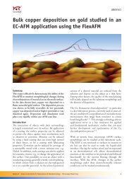
Conventional and co-axial<br />
probe forming systems<br />
Any design of a SIMS instrument must accommodate two conflicting needs: the objective lens of the primary ion<br />
column must be as close as possible to the sample in order to optimize its optical properties, leading to small<br />
and intense ion beam.<br />
On the other hand, secondary ions are emitted in a half-space, with a large energy spectrum (~ 0-200eV). In<br />
order to collect as a large fraction of these ions as possible, the extraction optics should also be placed as close<br />
as possible to the sample. As the extraction and objective optics have their own physical size, a compromize<br />
must be found leading to large sample/optics distances. The <strong>NanoSIMS</strong> design has escaped from this dilemna<br />
by switching to a totally new co-linear optics capable of simultaneously focusing the primary ions with high<br />
quality, and collecting most of the secondary ions.<br />
Primary beam<br />
Secondary beam<br />
Primary beam<br />
Secondary beam<br />
Probe<br />
forming<br />
optics<br />
Extraction<br />
optics<br />
Deflection<br />
plates<br />
Extraction<br />
and probe<br />
forming<br />
optics<br />
Sample<br />
Conventional<br />
SIMS<br />
Sample<br />
Co-axial<br />
<strong>NanoSIMS</strong><br />
Advantages of co-axial configuration :<br />
• Short working distance of the probe forming lens/ extraction<br />
1) smaller spot size for a given beam current<br />
2) higher collection efficiency and dramatical reduction of the broadening of the secondary ion beam<br />
due to the initial angular and energy distribution.<br />
This will favour transmission of the analyzer at high mass resolution.<br />
• Minimization of shadowing effects for non flat surfaces; hole or trench bottom analysis capability<br />
• Obtention of deep craters of small size<br />
• Reduction of the beam and raster distorsion<br />
Constraints due to co-axial configuration :<br />
• Primary and secondary ions must be of opposite polarity and equal energy (Cs + / negative ions, O - / positive<br />
ions). This excludes MCs + technique and the use of O2+ ions for electropositive elements.<br />
• Oxygen flooding can not be used<br />
<strong>NanoSIMS</strong> <strong>50</strong>
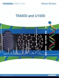
Lateral resolution with cesium<br />
The use of cesium primary ions is mandatory in SIMS for the analysis of electro-negative elements (H, C, O, N, F, Cl, P,<br />
Ge, Se, As, Br, Te, I, Au…). It enhances the ionization yield (= sensitivity) by several orders of magnitude compared to<br />
non-reactive primary species (Ar, Ga, Au, Bi…).<br />
The <strong>NanoSIMS</strong> is equipped with the patented CAMECA Microbeam cesium ion source, guaranteeing the highest<br />
brightness available among commercial cesium ion sources. The source brightness (in mA/sr/cm 2 ) measures the ion<br />
current available within a given solid angle from a given source area. It is an invariant in optics: a perfect (= without<br />
optical aberration) primary ion column could at maximum re-obtain this brightness in the final spot size. The high<br />
brightness of the ion source, the short final objective working distance, its reduced aberration coefficients, and the<br />
normal incidence guarantee the best performance available from a SIMS microprobe for electronegative secondary ion<br />
microanalysis.<br />
Beam spot size (= lateral resolution) is determined by extracting the 16%-84% intensity line-scan from a SIMS image of<br />
a TiCN sample giving sharp grain boundaries without artifact. Condition: 16 keV Cs + , negative secondaries.<br />
12<br />
C 2<br />
12<br />
C 14 N<br />
300nm<br />
Field: 4 X 4 µm, 512X512 pixels, Acq time: 30min.<br />
300nm<br />
12<br />
C 2<br />
12<br />
C 14 N<br />
Measured lateral<br />
resolution: 25nm<br />
200nm<br />
Field: 2.5 X 2.5 µm, 256X256 pixels, Acq time: 22min.<br />
200nm<br />
Conservative spot size specification (16-84%) for Cs + :<br />
<strong>50</strong>nm/0.3pA, 100nm/2pA.<br />
<strong>NanoSIMS</strong> <strong>50</strong><br />
Sample by courtesy of LAM, Luxemburg
Lateral resolution with oxygen<br />
The <strong>NanoSIMS</strong> is equipped with the high brightness CAMECA duoplasmatron ion source. Although it can<br />
generate positive ions (0 2+ ), it is mainly used in the <strong>NanoSIMS</strong> to generate 0 - ions. Due to the opposite<br />
polarity scheme, one can benefit from the strong ionization enhancement of electropositive elements with<br />
oxygen implantation. Additionally, the use of primary negative ions offers the well-known advantage of much<br />
lower sample charging problems compared with positive primary ions (the sample always tends to charge<br />
positively due to the secondary electron eec emission).<br />
sso The beam spot size is determined by extracting the 16%-84% intensity line-scan from a 27 Al + SIMS image<br />
recorded here on a sample containing Al grains.<br />
27Al +<br />
100%<br />
Intensity (A.U)<br />
84%<br />
16%<br />
O - : 0.3pA,<br />
16-84% < 170 nm<br />
0.0 1.0<br />
2.0<br />
Distance (microns)<br />
Field: 7.5 µm x 7.5 µm, 16-84% spot size: 170 nm, O-: 0.3pA<br />
27Al +<br />
100%<br />
Intensity (A.U)<br />
84%<br />
16%<br />
O - : 2pA,<br />
16-84% < 340 nm<br />
0%<br />
0.0 1.0<br />
2.0<br />
Distance (microns)<br />
Field: 10 µm x 10 µm, 16-84% spot size: 340 nm, O-: 2pA<br />
Conservative spot size specification (16-84%) in O - :<br />
200nm/0.3pA, 400nm/2pA.<br />
<strong>NanoSIMS</strong> <strong>50</strong><br />
O 2- current specs typically four time lower than O - .
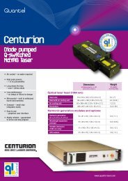
Analyzer Transmission<br />
versus Mass Resolution<br />
MRP T (%)<br />
3<strong>50</strong>0 100<br />
5910 68<br />
6120 65<br />
6770 56<br />
7120 51<br />
7390 45<br />
7885 39.9<br />
9470 29<br />
9615 24.5<br />
Without any slit, mass<br />
resolution is 3<strong>50</strong>0 and<br />
transmission is taken as<br />
100%. Other transmissions<br />
are referred to this one.<br />
Transmission<br />
e transmission<br />
relative Relative T<br />
100<br />
90<br />
80<br />
70<br />
60<br />
<strong>50</strong><br />
40<br />
30<br />
20<br />
10<br />
0<br />
100% Other transmissions 2000 3000 4000 <strong>50</strong>00 6000 7000 8000 9000 10000<br />
mass resolving power<br />
Mass Revolving Power<br />
Mass resolution is taken as M/dM = R/4 * L 10-90 , where R is trajectory radius<br />
and L 10-90 is line width corresponding to 80 % of intensity<br />
Optimized for lateral resolution and sensitivity, the <strong>NanoSIMS</strong> is a pure ion Microprobe (scanned<br />
focused ion beam) and has no ion microscope mode (transport of a stigmatic, magnified mass<br />
filtered ion image) as on the CAMECA IMS analyzers.<br />
One of the characteristics of the <strong>NanoSIMS</strong> is to work in high mass resolution: by design, there is<br />
no low mass resolution mode on the <strong>NanoSIMS</strong>, even when removing all apertures.<br />
In addition, the analyzer transmission is maintained very high (see plot above), even en when<br />
increasing the Mass Resolution. This is the result of:<br />
- a very high, normal extraction field allowing a very early secondary ion focusing,<br />
- a limited field of view together with a dynamic emittance matching,<br />
- a careful transport and rectangular shaping of the secondary beam resulting in<br />
the use of small slit compared to the magnet size, reducing aberrations,<br />
- the correction of the second order mass spectrometer optical aberrations.<br />
<strong>NanoSIMS</strong> <strong>50</strong>
<strong>NanoSIMS</strong> <strong>50</strong> main options<br />
NEG. Normal incidence Electron flood Gun for the analysis of strong electrical insulators in Cs + with negative<br />
secondary ions, when gold coating method is not sufficient, at high beam current.<br />
SED. Secondary Electron Detector. Works only in negative secondary polarity with cesium primary ions. Can<br />
give nicely contrasted topographical images for illustration and sample visualization.<br />
Full-MDA. Motor Driven Apertures. Automation of diaphragms, apertures and hexapole for an easier<br />
operation, a better reproducibility and a higher throughput.<br />
Z-motor. Automation of the sample stage Z-axis. Allows to re-adjust the sample Z position for sub-permil<br />
isotopic ratio reproducibility in geochemistry, in automated or chain acquisition mode.<br />
Geo-Faraday. Low-noise FC electrometer for geological applications in single FC-EMs mode.<br />
Dual-Faraday. Special trolleys #1 & #2 derived from NS<strong>50</strong>L design, equipped with both E.M. and F.C.,<br />
allowing FC-EM or FC-FC acquisition modes. Includes thermostated FC preamplifier chamber with<br />
intercalibration. Keeps the standard FC attached to the the lower mass side of trolley #1.<br />
NMR H/D. Additional NMR probe to ensure the best long term stability for hydrogen-deuterium measurements<br />
(the B field is too low for the standard NMR probe to improve the stability compared to the standard Hall probe<br />
regulation mode).<br />
<strong>NanoSIMS</strong> <strong>50</strong><br />
Note: all options are field-retrofittable
<strong>NanoSIMS</strong> <strong>50</strong>L<br />
The Multicollection analyzer of the <strong>NanoSIMS</strong> <strong>50</strong> can measure five masses with two key characteristics:<br />
1) Mass Dispersion (M max /M min in a parallel acquisition)<br />
= 13.2 (or 14.4 with LD option).<br />
For ex, one can follow 12C on trolley #1 and get mass 12 x 13 =<br />
156amu on the fixed detector #5 at large radius.<br />
2) Due to the finite width of the detectors and their<br />
angle relative to the focal plane, the minimum Mass<br />
Interval between two adjacent detectors is Mmax/30.<br />
Ex: 27, 28, 29, 30amu can be analyzed simultaneously but 57,<br />
58, 59, 60amu require two acquisitions: 57 & 59 then 58 & 60.<br />
8mm<br />
NS<strong>50</strong><br />
The <strong>NanoSIMS</strong> <strong>50</strong>L receives a larger Multicollection analyzer improving several specifications:<br />
-with the introduction of exit cylindrical sectors, the Mass Separation between een adjacent detectors is Mmax/58.<br />
- the magnet size is enlarged in order to reach a Mass Dispersion M max /M min = 21.<br />
- seven masses can be measured in parallel (five on the NS<strong>50</strong>)<br />
- in standard: one FC and seven EMs. In option, each trolley can be equipped with E.M. and FC.<br />
M max /58<br />
NS<strong>50</strong>L<br />
M max /M min = 21<br />
Side view of four trolleys of the<br />
NS<strong>50</strong>L multicollection<br />
7 masses in parallel (ex: all O and Si isotopes in parallel, or <strong>50</strong>-52-53-54Cr + 51V +48Ti + 55Mn)<br />
Up to 58Fe in multicollection and single mass separation (Ti, Cr, Mn, Fe isotopes accessible)<br />
Seven Faraday Cup option.<br />
<strong>NanoSIMS</strong> <strong>50</strong>
<strong>NanoSIMS</strong> <strong>50</strong>/<strong>50</strong>L<br />
The <strong>NanoSIMS</strong> <strong>50</strong>L mainly differs from the NS<strong>50</strong> by its larger multicollection and associated larger turbo-pump. Some<br />
other, minor differences: the Z-motor, optional on the NS<strong>50</strong>, is standard in the NS<strong>50</strong>L, and the LD large detector option<br />
of the NS<strong>50</strong> is not available on the NS<strong>50</strong>L.<br />
The general size of the instrument is not changed dramatically as can be seen from photos below:<br />
Standard NS<strong>50</strong><br />
NS<strong>50</strong>L<br />
<strong>NanoSIMS</strong> <strong>50</strong><br />
NS<strong>50</strong>L
Full-MDA option (NS<strong>50</strong>/<strong>50</strong>L),<br />
Seven-Faraday (NS<strong>50</strong>L) and Dual Faraday (NS<strong>50</strong>)<br />
1) Full-MDA: the <strong>NanoSIMS</strong> <strong>50</strong> and <strong>50</strong>L can both be equipped or<br />
retrofitted with the automation of D0 and D1 diaphragms, entrance, aperture<br />
and energy slits, hexapole centering, and individual trolley exit slit exchange.<br />
The benefits are an easier operation (important specially for multi-user<br />
operation), a better reproducibility for high precision isotopic ratios (subpermil<br />
level) and a higher throughput (faster tuning checks or pre-sputter at<br />
high current followed by analysis at high resolution in a chain analysis, etc…).<br />
Automated D0<br />
primary diaphragm<br />
Energy Slit<br />
Entrance & Aperture<br />
Slits<br />
Z-axis of the sample<br />
stage<br />
D1 co-axial lens<br />
diaphragm<br />
Automated exit slit exchange<br />
2) Seven-Faraday: each trolley of the <strong>NanoSIMS</strong> <strong>50</strong>L is equipped simultaneously with one E.M and one F.C.<br />
This allows to achieve deep sub-permil isotope ratio reproducibility using primary currents of a few nA. Each FC has<br />
its own preamplifier inside the thermostated FC preamp. chamber. The EM/FC selection is done multicollection<br />
opened at atmospheric pressure by mechanically sliding the detector behind the exit slit. There is no more FC<br />
attached on the smaller radius side of the trolley #1.<br />
FC<br />
EM<br />
Thermostated low-noise Seven FC<br />
preamplifier chamber allowing<br />
intercalibration of the FC signals.<br />
Synoptic of NS<strong>50</strong>L Seven-Faraday option<br />
NS<strong>50</strong>L detector trolley showing scanning<br />
plates, exit slit mechanism, cylindrical<br />
sector and detectors (EM and FC)<br />
3) Dual-Faraday is a standard <strong>NanoSIMS</strong> <strong>50</strong> option. The two lowest radius trolleys #1 and #2 are equipped<br />
simultaneously with one E.M and one F.C. Each FC has its own preamplifier inside the thermostated FC preamp.<br />
chamber. The EM/FC selection is done multicollection opened at atmospheric pressure by mechanically sliding the<br />
detector behind the exit slit. Note that contrary to the 7FC option of the NS<strong>50</strong>L, this option keeps the (third) FC<br />
attached on the lower side of trolley #1 of the NS<strong>50</strong>.<br />
<strong>NanoSIMS</strong> <strong>50</strong>
<strong>NanoSIMS</strong> sample mounting 1/2<br />
The standard <strong>NanoSIMS</strong> holder is <strong>50</strong>mm in diameter. The front plate can be customized depending on the user needs. Sample<br />
thickness can be up to 9mm. The sample surface must be flat. The Z movement of the sample stage can be used to keep<br />
sample/extraction distance at 400µm +/- <strong>50</strong>µm. Due to the small sample-lens distance, the sample must not degas too much in<br />
order to avoid risks of arcing. Typical working condition is in the E-9/ E-10 torr range. We thus recommend to minimize, if any, the<br />
embedding material volume. Gold coating of the sample is generally used in order to reduce sample charging problems.<br />
Below is a schematic of a <strong>NanoSIMS</strong> sample holder with 10mm holes (different hole sizes are available), with parts giving an idea of<br />
some possible mountings. For an easier viewing, the schematics are not at scale.<br />
PARTS<br />
SOME SAMPLE MOUNTINGS<br />
0.1mm<br />
Attention! If rectangular sample, check<br />
its diagonal to be less than 10.4mm !<br />
Ø9mm<br />
Ø10.4mm<br />
+0, -0.05<br />
Gold<br />
Part of the sample holder.<br />
Material: ARCAP AP4<br />
Ø10mm<br />
+0, -0.1<br />
Intermediate<br />
variable<br />
Ø10mm<br />
+0, -0.1<br />
ring.<br />
Material: ARCAP AP4<br />
Thin flat sample glued or fixed with non-degasing<br />
(< 1E-9 Torr) conductive double-side sticky tape<br />
4mm<br />
film<br />
Thicker flat sample glued or fixed with non-degasing<br />
(< 1E-9 Torr) conductive, double-side sticky tape<br />
Metallic cylinder.<br />
Material: ARCAP AP4<br />
Part #: 45620693<br />
0.1mm<br />
Ø10mm<br />
+0, -0.1<br />
4mm<br />
Ø10mm<br />
+0, -0.1<br />
Four<br />
Ø9mm<br />
Thin plate with holes.<br />
Four holes of diam. 3mm.<br />
Material: Z2-CN18-10,<br />
Part #: 45620694<br />
Small particles pressed into a gold foil<br />
Embedding ring.<br />
Material: ARCAP AP4, Part #: 45620692<br />
Attention! If rectangular sample to be embedded,<br />
check its diagonal to be less than 9mm !<br />
EOS<br />
Amagnetic Spring<br />
Small sample(s) analyzed through the<br />
holes of the thin top « grid » or « plate »<br />
EOP<br />
03mm 0.3mm<br />
Metal<br />
cylinder<br />
EOW<br />
Sample<br />
holder<br />
same<br />
potential<br />
Coaxial optics showing the short working distance<br />
Embedding in high vacuum resin or metal in metallic cylinder,<br />
then polished (or not if it is flat) and gold coated if needed.<br />
Ex: Korapox 439 epoxy (www.koemmerling-chemie.de),<br />
Varian Torr Seal Low Vapor Pressure Resin (www.varianinc.com).<br />
Also used: Wood metal (In-Bi alloy melting at 78°C)<br />
<strong>NanoSIMS</strong> <strong>50</strong>
<strong>NanoSIMS</strong> sample mounting 2/2<br />
<strong>50</strong>mm/ 2-inch diameter<br />
«WU-MPI» sample holder<br />
with one 1-inch , two halfinch<br />
and two 10mm holes.<br />
Ref #: 45620643<br />
25mm/ 1-inch diameter<br />
«Standard» sample holder<br />
with four 10mm holes.<br />
Ref #: 45620641<br />
<strong>50</strong>mm/ 2-inch diameter<br />
«Biology» sample holder<br />
with eight 10mm holes.<br />
Ref #: 45620642<br />
Shuttle<br />
Ref # : 45621551<br />
Reverse view of the « Biology» sample holder, unscrewed<br />
from its shuttle. One can see the springs pushing the<br />
sample cylinders in their hole against their lips.<br />
It is possible to simultaneously load two shuttles on the<br />
<strong>NanoSIMS</strong> sample stage : two 1-inch sample holders, or<br />
one 1-inch and one 2-inch sample holder. Note that the<br />
second 1-inch sample holder can be brought in SIMS<br />
position but not in the optical microscope position. It is<br />
generally used to store standard samples.<br />
The <strong>NanoSIMS</strong> is delivered with eight shuttles and eight<br />
sample holders: one “standard” and seven to be chosen<br />
within the different models available (not all displayed in<br />
this page, ask for a complete list).<br />
Ex. of wrong mounting ! Must be<br />
remounted with front reference.<br />
Thin samples (ex: biological sections)<br />
must be deposited on the POLISHED<br />
side of the metallic cylinder !<br />
Biological thin cross-section<br />
deposited on 7.3x7.3mm silicon<br />
square (diagonal=10 10.3mm).<br />
Sample under 4-<br />
hole thin plate<br />
Embedded<br />
sample<br />
10mm diam.<br />
embedding ring<br />
Ref #: 45620692<br />
10mm metallic cylinder<br />
Ref #: 45620693<br />
4-hole thin plate<br />
Ref #: 45620694<br />
Embedded<br />
sample<br />
Finger contacting the front<br />
electrode of the objective lens.<br />
<strong>NanoSIMS</strong> <strong>50</strong>
CORPORATE HEADQUARTERS<br />
CAMECA<br />
29 Quai des Grésillons<br />
92622 Gennevilliers Cedex - France<br />
Tel.: +33 1 43 34 62 00<br />
Fax: +33 1 43 34 63 <strong>50</strong><br />
E-mail: gennev@cameca.com<br />
Web-site: www.cameca.com<br />
MAIN INTERNATIONAL OFFICES<br />
CAMECA Germany Edisonstrasse 3, D-85716<br />
Unterschleissheim - Germany<br />
Tel.: +49 89 315 891-0<br />
Fax: +49 89 315 891-9999<br />
E-mail: sales.germany@cameca.com<br />
CAMECA Instruments, Inc. 4301 Garrity Blvd, #201<br />
Nampa, ID 83687 - U.S.A.<br />
Tel.: +1 208 442-6559<br />
Fax: +1 208 442-6595<br />
E-mail: sales.usa@cameca.com<br />
CAMECA Instruments Japan K.K.<br />
CAMECA Korea C°., Ltd.<br />
CAMECA Taiwan Corp. Ltd.<br />
8F Mikuni-East Bldg<br />
6-13-10, Sotokanda<br />
Chiyoda-ku, Tokyo 101-0021 - Japan<br />
Tel.: + 81 3 6831-6111<br />
Fax: + 81 3 6831-6112<br />
E-mail: sales.japan@cameca.com<br />
#309, 3rd Floor, Gyeonggi R&DB Center<br />
906-5 Iui-dong, Yeongtong-gu, Suwon-city<br />
Gyeonggi-do, Korea, 443-270<br />
Tel.: + 82 31-888-5225<br />
Fax: + 82 31-888-5228<br />
E-mail: sales.korea@cameca.com<br />
A2, 10F-6, No. 120, Sec. 2, GongDaoWu Rd.<br />
30056 Hsin Chu, Taiwan (R.O.C)<br />
Tel: + 886 3 57<strong>50</strong>099<br />
Fax: + 886 3 57<strong>50</strong>799<br />
E-mail: sales.taiwan@cameca.com<br />
<strong>NanoSIMS</strong> <strong>50</strong>