Download - MCM Electronics
Download - MCM Electronics
Download - MCM Electronics

Create successful ePaper yourself
Turn your PDF publications into a flip-book with our unique Google optimized e-Paper software.
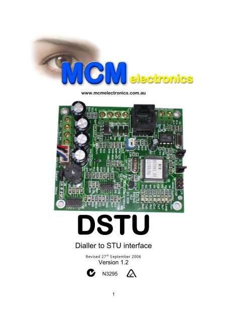
www.mcmelectronics.com.au<br />
DSTU<br />
Dialler to STU interface<br />
Revised 27 th September 2006<br />
Version 1.2<br />
N3295<br />
1
General Description<br />
The DSTU is an interface between an alarm panel reporting Contact ID and an <strong>MCM</strong> Securitel<br />
RS232STU. This interface enables the alarm panel to communicate via its PSTN connection.<br />
The DSTU emulates the PSTN telephone network and provides a DC line voltage together with<br />
optional simulated dial tone (link selectable).<br />
The DSTU acts as a Central Station Receiver generating Handshake and Acknowledge tones.<br />
The DSTU receives the Contact ID and translates the data as per the table below, then sends<br />
this data to the <strong>MCM</strong> RS232STU. The STU sends the event via the Securitel network using<br />
standard ASIAL Serial Data (ASD) format.<br />
System Wiring<br />
The Alarm Panel connects to the DSTU via PSTN (phone line terminal) and also 12volts DC. The<br />
DSTU connects to an <strong>MCM</strong> RS232 STU (4 wire) and the STU in turn is connected to the Securitel<br />
Line.<br />
The DSTU requires 12Vdc power supply @25mA....plus the 232STU@60mA<br />
The DSTU has connections for:<br />
• 12Vdc Input Power<br />
• PANEL RJ11 (panel connection)<br />
• + - Rx Tx. 4 wire connection to an <strong>MCM</strong> STU<br />
Control Panel Programming<br />
Setup these functions in the Alarm Panel:<br />
• Account Number…. This will become the STUs Hard ID<br />
• Contact ID Reporting<br />
• DTMF Tone Dialing<br />
• 1 or more Telephone Number digits; eg. 1 2 3 (Any digits)<br />
• Setup all the desired alarm and system reporting codes.<br />
Initial System Setup<br />
The DTU must receive an event (e.g. alarm /open /close) so it can receive the Account Number.<br />
The account number of the panel is then used as the Hard ID. This account number is then sent<br />
to the STU so that the STU can be brought on line (Upped).<br />
Note….<br />
Make sure only one account number is used (Not Multi Account number)<br />
If using a multi-partition Control Panel, ensure all account numbers are identical.<br />
Normal Operation.<br />
Panel makes a telephone call to report an event. When the DSTU detects the panel going offhook,<br />
the Loop LED on the DSTU operates. If J3 is linked, the DSTU will generate dial tone for<br />
up to 4 seconds and listen for the phone number to be dialled. (if a digit is detected Dial tone<br />
stops). When the panel finishes dialing, the DSTU generates a Handshake (as a normal Central<br />
Station receiver would). The panel transmits its account number and Contact ID event code.<br />
If a valid message is received an Acknowledge or Kiss-off signal is sent to the panel.<br />
Further events can be received on the same call. The DSTU translates the received account<br />
number and Contact ID event and sends this account number to the STU to be used as the<br />
Hard ID. The event data is sent to the STU as Serial data. Once this first transmission is<br />
received STU can be UPPED. Events are then sent as serial data using the translation table<br />
below.<br />
2
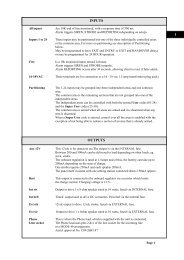
Indicators<br />
The DSTU has multiple LEDs to indicate the progress of the transmission and the status of the<br />
DSTU. These LEDs indicate the following ….<br />
Run will flash every second.<br />
Loop indicates when the panel has looped the line to the DSTU.<br />
RxT Receiving tone from the panel to the DSTU.<br />
TxT Transmiting tone from the DSTU to the panel. (Dial tone, Handshake or Acknowledge)<br />
Evt An event has been received by the DSTU and is waiting to be sent to STU.<br />
Acc An account number received by the DSTU from the panel. On after 1 st event received.<br />
TxD transmit data to the STU. Flashes every 1-3 seconds in normal operation.<br />
RxD receive data from the STU. Flashes every 1-3 seconds in normal operation.<br />
Out1 Status of Output1. On for 1 second every 1 Hr or 4 Hrs depending on J3 pin 7 and 8.<br />
Out1 can be used to trigger the panel to do a 1 hourly or 4 hourly test.<br />
Onboard Speaker<br />
The onboard speaker can be enabled with a link. This speaker gives audible output of<br />
communications between the dialler and DSTU.<br />
3
Wiring<br />
Power<br />
+ 12V and – 0v terminals connect to the panels +12V and – source. To make wiring easier, 2<br />
terminals are provided with +12v and – 0v connections. Both terminals are wired in parallel<br />
therefore power can be connected to either one. It’s recommended to run power from the panel<br />
to the J7 terminal block and power out to the STU from J5 terminal block or J6 if the STU has a<br />
4-pin header. This will result in a neater installation.<br />
Input 1<br />
The input does not require an EOL (End of Line) resistor. The input can be triggered via a GND<br />
with a response time of around 300ms. It can be programmed to send its own event to the<br />
STU.<br />
Out1<br />
The output can be used to trigger the panel if an event hasn’t been received for a period of time<br />
or wake it up to generate a test signal. The output can sink 100ma MAX.<br />
Tx & Rx<br />
Tx & Rx connections from J5 & J6 connect to the STU. A 4pin header and terminal block are<br />
provided for convenience, only one is required to be connected at any one time.<br />
Panel<br />
This is connected to the panel’s dialler via the RJ45 socket or terminal block. Only the two<br />
centre pins usually red and green are required on the telecom lead from the panel to the DSTU.<br />
Technical Specifications<br />
Nominal Input Voltage:<br />
Maximum Input Voltage:<br />
Maximum Current Draw:<br />
Minimum Current Draw:<br />
Input EOL Resistor:<br />
Output type:<br />
Maximum Output Current:<br />
+12v DC<br />
+15v DC<br />
110ma<br />
20ma<br />
No EOL required<br />
Output transistor, switches to GND.<br />
100ma<br />
4
Contact ID translation to ASIAL Serial Data (ASD)<br />
ALARM CLASSIFICATION - ALARM<br />
Contact ID Code<br />
ASD Code or Point Number<br />
E10? - Medical 06 Alarm point 200<br />
R10? - Medical Restore 08 Restore point 200<br />
E11? - Fire 06 Alarm point 201<br />
R11? - Fire Restore 08 Restore point 201<br />
E120 - Panic 06 Alarm point 202<br />
R120 - Panic Restore 08 Restore point 202<br />
E121 - Duress 06 Alarm point 203<br />
R121 - Duress Restore 08 Restore point 203<br />
…Other 12? Alarms/Restores….<br />
E12? - Alarm 06 Alarm point 204<br />
R12? - Restore 08 Restore point 204<br />
E137 - Tamper Alarm 06 Alarm point 205<br />
R137 - Tamper Restore 08 Restore point 205<br />
Where ? is digits 0-9<br />
Where xxx is the Point or Section# received.<br />
…Other Alarms/Restores….<br />
* * * Any 1xx series event code received that is not defined above will generate an ASD<br />
event code of 06 for an E (new trouble) or 08 for an R (new trouble restore) in line with<br />
the above but with the Point Number. (Point numbers above 220 will be sent as 220)<br />
* * * Any 200 Series event code received will generate an ASD event code of 12 for an E<br />
(new trouble) or 14 for an R (new trouble restore) in line with the above but with a<br />
Point Number of 220.<br />
TROUBLES CLASSIFICATION - TROUBLE<br />
Contact ID Code<br />
ASD Code or Point Number<br />
E300 - System Trouble 12 Trouble Alarm Point 255<br />
R300 - System Trouble Restore 14 Trouble Rest. Point 255<br />
E301 - AC Power Loss 12 Trouble Alarm Point 254<br />
R301 - AC Power Restore 14 Trouble Restore Point 254<br />
E302 - Low System Battery 12 Trouble Alarm Point 253<br />
R302 - Low System Battery Restore 14 Trouble Rest. Point 253<br />
E303 - RAM Checksum Bad 12 Trouble Alarm Point 252<br />
E304 - ROM Checksum Bad 12 Trouble Alarm Point 251<br />
E305 - System Reset 12 Trouble Alarm Point 250<br />
E306 - Panel Programming Changed 12 Trouble Alarm Point 249<br />
E310 - Ground Fault 12 Trouble Alarm Point 245<br />
R310 - Ground Fault Restore 14 Trouble Rest. Point 245<br />
E320 - Sounder/Relay Trouble 12 Trouble Alarm Point 244<br />
R320 - Sounder/Relay Restore 14 Trouble Rest. Point 244<br />
E321 - Bell 1 Trouble 12 Trouble Alarm Point 243<br />
R321 - Bell 1 Restore 14 Trouble Rest. Point 243<br />
E322 - Bell 2 Trouble 12 Trouble Alarm Point 242<br />
R322 - Bell 2 Restore 14 Trouble Rest. Point 242<br />
E323 - Alarm Relay Trouble 12 Trouble Alarm Point 241<br />
R323 - Alarm Relay Restore 14 Trouble Rest. Point 241<br />
5
E324 - Trouble Relay Trouble 12 Trouble Alarm Point 240<br />
R324 - Trouble Relay Restore 14 Trouble Rest. Point 240<br />
E325 - Reversing Relay Trouble 12 Trouble Alarm Point 239<br />
R325 - Reversing Relay Restore 14 Trouble Rest. Point 239<br />
E330 - System Peripheral Trouble 12 Trouble Alarm Point 238<br />
R330 - System Peripheral Restore 14 Trouble Rest. Point 238<br />
E331 - Polling Loop Open 12 Trouble Alarm Point 237<br />
R331 - Polling loop Open Restore 14 Trouble Rest. Point 237<br />
E332 - Polling Loop Short 12 Trouble Alarm Point 236<br />
R332 - Polling Loop Short Restore 14 Trouble Rest. Point 236<br />
E333 - Expansion Module Failure 12 Trouble Alarm Point 235<br />
R333 - Expansion Module Restore 14 Trouble Rest. Point 235<br />
E334 - Repeater Failure 12 Trouble Alarm Point 234<br />
R334 - Repeater Restore 14 Trouble Rest. Point 234<br />
E335 - Local Printer Paper Out 12 Trouble Alarm Point 233<br />
R335 - Local Printer Paper Restore 14 Trouble Rest. Point 233<br />
E336 - Local Printer Failure 12 Trouble Alarm Point 232<br />
R336 - Local Printer Restore 14 Trouble Rest. Point 232<br />
E350 - Communication Trouble 12 Trouble Alarm Point 231<br />
R350 - Communication Restore 14 Trouble Rest. Point 231<br />
E351 - Telecom 1 Fault 12 Trouble Alarm Point 230<br />
R351 - Telecom 1 Restore 14 Trouble Rest. Point 230<br />
E352 - Telco 2 Fault 12 Trouble Alarm Point 229<br />
R352 - Telco 2 Restore 14 Trouble Rest. Point 229<br />
E353 - Long Range Radio Xmitter Fault 12 Trouble Alarm Point 228<br />
R353 - Long Range Radio Xmitter Rest. 14 Trouble Rest. Point 228<br />
E354 - Failure to Communicate Event 12 Trouble Alarm Point 227<br />
R354 - Fail to Communicate Restore 14 Trouble Rest. Point 227<br />
E355 - Loss of Radio Supervision 12 Trouble Alarm Point 226<br />
R355 - Restore of Radio Supervision 14 Trouble Rest. Point 226<br />
E356 - Loss of Central Polling 12 Trouble Alarm Point 225<br />
R356 - Restore of Central Polling 14 Trouble Rest. Point 225<br />
E370 - Protection Loop 12 Trouble Alarm Point 224<br />
R370 - Protection Loop Restore 14 Trouble Rest. Point 224<br />
E371 - Protection Loop Open 12 Trouble Alarm Point 223<br />
R371 - Protection Loop Open Restore 14 Trouble Rest. Point 223<br />
E372 - Protection Loop Short 12 Trouble Alarm Point 222<br />
R372 - Protection Loop Short Restore 14 Trouble Rest. Point 222<br />
E373 - Fire Trouble 12 Trouble Alarm Point 221<br />
R373 - Fire Trouble Restore 14 Trouble Rest. Point 221<br />
E380 - Trouble (Global) 0E Tamper Alarm Point xxx<br />
R380 - Trouble (Global) Restore 10 Tamper Rest. Point xxx<br />
E381 - Loss of Supv. RF 0E Tamper Alarm Point xxx<br />
R381 - Loss of Supv. RF Restore 10 Tamper Rest. Point xxx<br />
E382 - Loss of Supv. RPM 12 Trouble Alarm Point xxx<br />
R382 - Loss of Supv. RPM Restore 14 Trouble Rest. Point xxx<br />
E383 - RPM Sensor Tamper 0E Tamper Alarm Point xxx<br />
R383 - RPM Sensor Tamper Restore 10 Tamper Rest. Point xxx<br />
E384 - RF Low Battery 12 Trouble Alarm Point xxx<br />
R384 - RF Low Battery Restore 14 Trouble Rest. Point xxx<br />
Where xxx is the Point/Section# received.<br />
* * * Any 3xx series event code received that is not defined above will generate an ASD<br />
event code of 12 for an E (new trouble) or 14 for an R (new trouble restore) in line with<br />
the above but with a Point Number of 220.<br />
6
OPEN/CLOSE or Access CLASSIFICATION<br />
Contact ID Code<br />
ASD Code or Point Number<br />
E400 - Opening 31 Opening User 255<br />
R400 - Closing 51 Closing User 255<br />
E401 - Group 00 Open User # 31 Opening ALL User #xxx<br />
R401 - Group 00 Close User # 51 Closing ALL User #xxx<br />
E401 - Grps 01-30 Open User #<br />
32-50 Partial Open Grp 01-30 User #xxx<br />
R401 - Grps 01-30 Close User #<br />
52-70 Partial Close Grp 01-30 User #xxx<br />
E402 - Group 00 Open User # 31 Opening ALL User #xxx<br />
R402 - Group 00 Close User # 51 Closing ALL User #xxx<br />
E402 - Group Opening<br />
32-50 Opening Grp 01-30 User #xxx<br />
R402 - Group Closing<br />
32-50 Closing Grp 01-30 User #xxx<br />
E403 - Automatic Opening 31 Opening User 253<br />
R403 - Automatic Closing 51 Closing User 253<br />
E405 - Deferred Opening 31 Opening User 252<br />
R405 - Deferred Closing 51 Closing User 252<br />
E406 - Cancel 31 Opening User 251<br />
E407 - Remote Disarm 31 Opening User 250<br />
R407 - Remote Arm 51 Closing User 250<br />
R408 - Quick Arm 51 Closing User 249<br />
E409 - Keyswitch Disarm 31 Opening User 248<br />
R409 - Keyswitch Arm 51 Closing User 248<br />
E411 - Callback Request Made 06 Alarm point 236<br />
E412 - Successful <strong>Download</strong>/Access 06 Alarm point 235<br />
E413 - Unsuccessful Access 06 Alarm point 234<br />
E414 - System Shutdown Command Recv. 06 Alarm point 233<br />
E415 - Dialler Shutdown Command Recv. 06 Alarm point 232<br />
E421 - Access Denied 06 Alarm point 231<br />
E422 - Access Report by User 06 Alarm point 230<br />
R441 - Armed STAY 51 Closing User 247<br />
E450 - Exception Open 31 Opening User 246<br />
R450 - Exception Close 51 Closing User 246<br />
E451 - Early Open 31 Opening User 245<br />
R451 - Early Close 51 Closing User 245<br />
E452 - Late Open 31 Opening User 244<br />
R452 - Late Close 51 Closing User 244<br />
E453 - Failed to Open 31 Opening User 243<br />
E454 - Failed to Close 31 Opening User 242<br />
E455 - Auto Arm Failed 31 Opening User 241<br />
R456 - Partial Arm 51 Closing User 240<br />
E457 - Exit Error 31 Opening User 239<br />
E458 - User on Premises 31 Opening User 238<br />
R459 - Recent Close 51 Closing User 237<br />
* * * Groups > 30 will be sent as 30<br />
* * * Users above 220 will be sent as 220.<br />
* * * Any 400 series event code received that is not defined above will generate an ASD event<br />
code of 31 for an E (new opening) or 51 for an R (new closing) in line with the above but<br />
with a Point Number of 220.<br />
7
BYPASS / DISABLE CLASSIFICATION<br />
CONTACT ID EVENT ASD CODE POINT NUMBER<br />
E57? - Bypasses 16 Isolate Point xxx<br />
R57? - Bypasses Restore 18 D-Isolate Point xxx<br />
E520 - Sounder/Relay Disable 16 Isolate point 255<br />
R520 - Sounder/Relay Enable 18 D-isolate point 255<br />
E521 - Bell 1 Disable 16 Isolate point 254<br />
R521 - Bell 1 Enable 18 D-isolate point 254<br />
E522 - Bell 2 Disable 16 Isolate point 253<br />
R522 - Bell 2 Enable 18 D-isolate point 253<br />
E523 - Alarm Relay Disable 16 Isolate point 252<br />
R523 - Alarm Relay Enable 18 D-isolate point 252<br />
E524 - Trouble Relay Disable 16 Isolate point 251<br />
R524 - Trouble Relay Enable 18 D-isolate point 251<br />
E525 - Reversing Relay Disable 16 Isolate point 250<br />
R525 - Reversing Relay Enable 18 D-isolate point 250<br />
E551 - Dialler Disabled 16 Isolate point 249<br />
R551 - Dialler Enabled 18 D-isolate point 249<br />
E552 - Radio Transmitter Disabled 16 Isolate point 248<br />
R552 - Radio Transmitter Enabled 18 D-isolate point 248<br />
* * * Any 500 series event code received that is not defined above will generate an ASD event code of<br />
16 for an E (new bypass) or 18 for an R (bypass restore) in line with the above but with a Point<br />
Number of 220.<br />
E601 - Test Manually Triggered 06 Alarm point 254<br />
E602 - Test Periodic 06 Alarm point 253<br />
E603 - Periodic RF Transmission 06 Alarm point 252<br />
E604 - Fire Test 06 Alarm point 251<br />
R604 - Fire Test 08 Restore point 251<br />
E605 - Status Report to Follow 06 Alarm point 250<br />
E606 - Listen-in to Follow 06 Alarm point 249<br />
E607 - Walk Test Mode Entered 06 Alarm point 248<br />
R607 - Walk Test Mode Exited 08 Restore point 248<br />
E621 - Event Log Reset 06 Alarm point 247<br />
E622 - Event Log 50% Full 06 Alarm point 246<br />
E623 - Event Log 90% Full 06 Alarm point 245<br />
E624 - Event Log Overflow 06 Alarm point 244<br />
E625 - Time/Date Reset 06 Alarm point 243<br />
E626 - Time/Date Inaccurate 06 Alarm point 242<br />
E627 - Program Mode Entry 06 Alarm point 241<br />
E628 - Program Mode Exit 06 Alarm point 240<br />
E630 - Schedule Change 06 Alarm point 239<br />
E631 - Exception Schedule Change 06 Alarm point 238<br />
E632 - Access Schedule Change 06 Alarm point 237<br />
* * * Any 200, 700, 800 and 900 series event code received will generate an ASD event code of 12 for<br />
an E (new trouble) or 14 for an R (new trouble restore) in line with the above but with a Point Number<br />
of 220.<br />
* * * Any 600 series event code received that is not defined above should generate an<br />
ASD event code of 06 for an E (new alarm) or 08 for an R (new restore) in line with<br />
the above but with a Point Number of 220.<br />
8