Chapter 8 Culvert Use, Installation, and Sizing
Chapter 8 Culvert Use, Installation, and Sizing
Chapter 8 Culvert Use, Installation, and Sizing

You also want an ePaper? Increase the reach of your titles
YUMPU automatically turns print PDFs into web optimized ePapers that Google loves.
<strong>Chapter</strong> 8<br />
Culver<br />
ert t <strong>Use</strong>, , <strong>Installation</strong>,<br />
tion,<br />
<strong>and</strong> <strong>Sizing</strong><br />
“Ensure that culverts are adequately sized or have overflow protection.”<br />
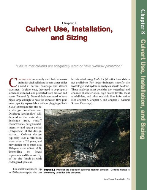
CULVERTS ARE commonly used both as crossdrains<br />
for ditch relief <strong>and</strong> to pass water under<br />
a road at natural drainage <strong>and</strong> stream<br />
crossings. In either case, they need to be properly<br />
sized <strong>and</strong> installed, <strong>and</strong> protected from erosion <strong>and</strong><br />
scour (Photo 8.1). Natural drainages need to have<br />
pipes large enough to pass the expected flow plus<br />
extra capacity to pass debris without plugging (Photo<br />
8.2). Fish passage may also be<br />
a design consideration.<br />
Discharge (design flow) will<br />
depend on the watershed<br />
drainage area, runoff<br />
characteristics, design rainfall<br />
intensity, <strong>and</strong> return period<br />
(frequency) of the design<br />
storm. <strong>Culvert</strong> design<br />
typically uses a minimum<br />
storm event of 20 years, <strong>and</strong><br />
may design for as much as a<br />
100-year event (Photo 8.3),<br />
depending on local<br />
regulations <strong>and</strong> the sensitivity<br />
of the site (such as with<br />
endangered species).<br />
be estimated using Table 8.1 (if better local data is<br />
not available). For larger drainages, specific site<br />
hydrologic <strong>and</strong> hydraulic analyses should be done.<br />
These analyses must consider the watershed <strong>and</strong><br />
channel characteristics, high water levels, local<br />
rainfall data, <strong>and</strong> other available flow information<br />
(see <strong>Chapter</strong> 5, <strong>Chapter</strong> 6, <strong>and</strong> <strong>Chapter</strong> 7- Natural<br />
Stream Crossings).<br />
<strong>Chapter</strong> 8 Culver<br />
Culv<br />
ert <strong>Use</strong>, <strong>Use</strong><br />
, <strong>Installation</strong>, Installa<br />
tion, <strong>and</strong> <strong>Sizing</strong><br />
For small watersheds (up<br />
to 120 hectares) pipe size can<br />
Photo 8.1 Protect the outlet of culverts against erosion. Graded riprap is<br />
commony used for this purpose.<br />
LOW-VOLUME ROADS BMPS:<br />
75
minimizing channel modifications;<br />
avoiding constriction of the<br />
bankfull flow channel width;<br />
maintaining the natural grade <strong>and</strong><br />
alignment; using quality, well<br />
compacted bedding <strong>and</strong> backfill<br />
material; <strong>and</strong> using inlet, outlet,<br />
<strong>and</strong> streambank protection<br />
measures (Photo 8.4). Trash racks<br />
(Figure 8.6) are often desirable in<br />
channels with significant amounts<br />
of debris to prevent pipe plugging<br />
(Photo 8.5).<br />
Photo 8.2 A culvert failure caused by insufficient flow capacity or<br />
inadequate pipe size to pass the debris (boulders) moving through the<br />
drainage.<br />
<strong>Culvert</strong>s are made of concrete<br />
or metal (corrugated steel or<br />
aluminum), <strong>and</strong> plastic pipe is<br />
occasionally used, as well as wood<br />
<strong>and</strong> masonry. The type of material<br />
used depends on cost <strong>and</strong><br />
availability of the materials.<br />
However, corrugated metal pipe<br />
(CMP) <strong>and</strong> concrete pipe are<br />
generally more durable than<br />
plastic pipe. The shape of the<br />
culvert, such as a round pipe, pipe<br />
arch, structural arch, or box,<br />
depends on the site, the needed<br />
span, <strong>and</strong> the allowable height of<br />
soil cover. The key factors in<br />
culvert selection are that the<br />
culvert has adequate flow<br />
capacity, fits the site, <strong>and</strong> that the<br />
installation is cost-effective.<br />
structure or catch basin, <strong>and</strong> the<br />
outlet area should be protected<br />
against scour.<br />
<strong>Culvert</strong> installation <strong>and</strong><br />
alignment factors for drainage<br />
crossings are shown in Figures<br />
8.2, 8.3, 8.4, <strong>and</strong> 8.5. Important<br />
installation details include:<br />
Bedding <strong>and</strong> backfill material<br />
for culverts is commonly specified<br />
as “select granular material” or<br />
“select mineral soil”. Actually,<br />
most soils are satisfactory if they<br />
are free of excessive moisture,<br />
muck, lumps of frozen soil, roots,<br />
highly plastic clay, or rock larger<br />
than 7.5 cm. Bedding material<br />
beneath the pipe should not have<br />
rocks larger than 3.8 cm. Clay soil<br />
can be used if it is carefully<br />
compacted at a uniform, nearoptimum<br />
moisture content. Ideal<br />
Cross-drain culvert<br />
installation options <strong>and</strong> details for<br />
ditch relief are seen in Figure 8.1,<br />
as well as Figures 7.6 <strong>and</strong> 7.7.<br />
The cross-drain pipe should<br />
ideally be placed at the bottom of<br />
the fill, the inlet should be<br />
protected with a drop inlet<br />
LOW-VOLUME ROADS BMPS:76<br />
Photo 8.3 Install masonry/concrete box or metal culverts with a large<br />
enough size (capacity) to safely pass the anticipated design flow<br />
(typically a 20- to 50-year recurrence event), based upon hydrological<br />
analysis. <strong>Use</strong> headwalls <strong>and</strong> wingwalls whenever possible.
ackfill material is a moist, wellgraded<br />
granular or s<strong>and</strong>y<br />
gravel soil with up to 10 percent<br />
fines <strong>and</strong> free of rocks. The<br />
material should be well<br />
compacted, at least as dense as the<br />
adjacent ground, <strong>and</strong> preferably at<br />
a density of 90-95% of the<br />
AASHTO T-99 maximum density.<br />
It should be placed in 15cm thick<br />
layers (lifts). A dense, uniform<br />
backfill is important to structurally<br />
support the lateral pressure from<br />
the pipe, particularly with plastic<br />
pipes.<br />
Uniform fine s<strong>and</strong> <strong>and</strong> silt soils<br />
can be problematic when used for<br />
culvert bedding or backfill<br />
material. These fine, non-cohesive<br />
soils are very susceptible to scour<br />
<strong>and</strong> piping from moving water<br />
(Photo 8.6). Thus their use is<br />
discouraged. If used, they should<br />
be very well compacted against<br />
the pipe. Ideally, a clay plug or<br />
anti-seepage collar, made of<br />
metal, concrete, or even<br />
geotextile, should be placed<br />
around the culvert pipe to force<br />
any water channel to flow in a<br />
longer path through the soil.<br />
Concrete headwalls also deter<br />
piping.<br />
Because of changing climatic<br />
conditions, debris <strong>and</strong> bedload in<br />
channels, changing l<strong>and</strong> use<br />
patterns, <strong>and</strong> uncertainties in<br />
hydrologic estimates, culvert size<br />
<strong>and</strong> capacity should be<br />
conservative, <strong>and</strong> should be<br />
oversized rather than undersized.<br />
Ideally, a culvert will be of a size<br />
as wide as the natural channel to<br />
avoid channel constriction.<br />
Channel protection, riprap,<br />
overflow dips, headwalls, <strong>and</strong><br />
trash racks can all help mitigate<br />
culvert problems, but none are as<br />
good as an adequately sized <strong>and</strong><br />
well placed pipe. An oversized<br />
culvert, designed to avoid pipe<br />
repairs or failure as well as<br />
prevent environmental damage,<br />
can be very cost-effective in the<br />
long run. Also, the addition of<br />
concrete or masonry headwalls<br />
helps reduce the likelihood of pipe<br />
plugging <strong>and</strong> failure.<br />
Pipe size, as a function of<br />
anticipated design flow (capacity)<br />
<strong>and</strong> headwater depth, can easily<br />
be determined using the<br />
Nomograms presented in Figures<br />
8.7a, 8.7b, <strong>and</strong> 8.7c. These figures<br />
apply to commonly used culverts<br />
of round corrugated metal pipe,<br />
Table le 8.1<br />
DRAINAGE STRUCTURE SIZING<br />
Drainage Area<br />
(Hectares)<br />
Size of Drainage Structure<br />
Inches <strong>and</strong> Area (m2)<br />
Steep Slopes<br />
Gentle Slopes<br />
Logged, Light Vegetation Unlogged, Heavy Vegetation<br />
C= 0.7 C=0.2<br />
Round Pipe (in) Area (m2) Round Pipe (in) Area (m2)<br />
0-4 30” 0.46 18" 0.17<br />
4-8 42" 0.89 24" 0.29<br />
8-15 48" 1.17 30" 0.46<br />
15-30 72" 2.61 42" 0.89<br />
30-50 84" 3.58 48" 1.17<br />
50-80 96" 4.67 60" 1.82<br />
80-120 72" 2.61<br />
120-180 84" 3.58<br />
Notes: If pipe size is not available, use the next larger pipe size for the given drainage area. For intermediate<br />
terrain, interpolate between pipe sizes.<br />
-Pipe size is based upon the Rational Formula <strong>and</strong> <strong>Culvert</strong> Capacity curves. Assumes a rainfall intensity of<br />
75 mm/hr. (3"/hr) to 100 mm/hr (4”/hr). Values of “C” are the Runoff Coefficients for the terrain.<br />
-For tropical regions with frequent high intensity rainfall (over 250 mm/hr or 10”/hr), these drainage areas<br />
for each pipe size should be reduced at least in half.<br />
LOW-VOLUME ROADS BMPS:<br />
77
Figur<br />
igure 8.1 <strong>Culvert</strong> cross-drain installation options in a fill.<br />
<strong>Culvert</strong><br />
cross-drain<br />
Yes<br />
No<br />
Outlet protection<br />
with rock riprap<br />
Erosion or scour<br />
unless slope<br />
protection is<br />
added.<br />
The outlet of the pipe should extend beyond the toe of the fill <strong>and</strong> should<br />
never be discharged on the fill slope without erosion protection.<br />
Optional<br />
Roadbed<br />
Compacted fill<br />
Inlet<br />
structure<br />
Pipe<br />
Anchor the downdrain<br />
pipe to the fill slope<br />
with stakes, cable,<br />
anchor blocks, etc.<br />
Natural Ground<br />
Optional use of a downdrain pipe, especially in large fills with poor soils <strong>and</strong> high<br />
rainfall areas, where fill settlement may require culvert repairs.<br />
round concrete pipe, <strong>and</strong> concrete<br />
boxes. Each of these figures<br />
applies to pipes with inlet control,<br />
where there is no constraint on the<br />
downstream elevation of the<br />
water exiting the structure.<br />
Ideally, the inlet water elevation<br />
(headwater depth) should not<br />
greatly exceed the height or<br />
diameter of the structure in order<br />
to prevent saturation of the fill <strong>and</strong><br />
minimize the likelihood of the pipe<br />
plugging from floating debris.<br />
More detailed information is<br />
found in FHWA Manual HDS-5,<br />
Hydraulic Design of Highway<br />
<strong>Culvert</strong>s, 1998)<br />
LOW-VOLUME ROADS BMPS:78<br />
Photo 8.4 A structural plate arch pipe culvert with stream bank<br />
protection using large rock riprap placed upon a geotextile filter<br />
layer.
Figur<br />
igure 8.2 <strong>Culvert</strong> alignment <strong>and</strong> installation detail (continued on next page).<br />
Poor – Requires a stream channel<br />
modification.<br />
Adequate – No channel modifications but<br />
requires a curve in the road.<br />
a. <strong>Culvert</strong> alignment options.<br />
Best – No channel modification, <strong>and</strong> the road is perpendicular<br />
to the culvert without a curve in the road alignment.<br />
Poor – Single pipe concentrates flow in the<br />
broad channel or floodplain.<br />
Better – Multiple pipes disperse the flow<br />
across the channel. Middle pipe may be<br />
slightly lower to pass the normal low flow<br />
<strong>and</strong> to promote fish passage.<br />
b. <strong>Culvert</strong> installation in a broad channel.<br />
LOW-VOLUME ROADS BMPS:<br />
79
Figur<br />
igure 8.2 (continued)<br />
NO – TOO DEEP<br />
NO – TOO HIGH<br />
YES<br />
Roadbed<br />
30 cm min.<br />
2<br />
Slope 1<br />
Seed <strong>and</strong> mulch or protect<br />
with riprap<br />
Do not change stream bottom elevation!<br />
c. Install culverts at natural stream grade.<br />
Figur<br />
igure e 8.3 <strong>Culvert</strong> backfill <strong>and</strong> compaction. (Adapted from Montana Department of State L<strong>and</strong>s, 1992)<br />
Roadbed<br />
At least 30 cm of cover<br />
for CMP or one-third of<br />
diameter for large<br />
culverts. <strong>Use</strong> 60 cm<br />
cover for concrete pipe.<br />
Base <strong>and</strong> sidewall fill<br />
material should be<br />
compacted. Compact the<br />
fill a minimum of one<br />
culvert diameter on each<br />
side of the culvert.<br />
<strong>Culvert</strong><br />
Tamp backfill material at<br />
regular intervals (lifts) of<br />
15 to 20 cm.<br />
Level of<br />
natural<br />
streambed<br />
gravel or soil<br />
culvert bed<br />
(no rock larger than 8 cm)<br />
Existing ground<br />
LOW-VOLUME ROADS BMPS:80
Figur<br />
igure 8.4 <strong>Culvert</strong> inlet <strong>and</strong> outlet protection.<br />
Geotextile or gravel filter (or both)<br />
a. Normal metal culvert installation using riprap around the inlet <strong>and</strong> outlet of culverts. Also use<br />
geotextile (filter fabric) or gravel filter beneath the riprap for most installations. (Adapted from<br />
Wisconsin’s Forestry Best Management Practice for Water Quality, 1995)<br />
b. Concrete box culvert with concrete wingwalls for inlet/outlet protection <strong>and</strong> fill retention.<br />
LOW-VOLUME ROADS BMPS:<br />
81
Figur<br />
igure 8.5 <strong>Culvert</strong> installation <strong>and</strong> outlet protection details with splash apron or rirap lined plunge<br />
pool.<br />
Headwall with or<br />
without<br />
wingwalls<br />
Entrance<br />
elevation<br />
Natural<br />
ground<br />
Slope 1½ : 1<br />
Roadbed width<br />
Fill<br />
30 cm min.<br />
Slope of channel<br />
Compacted<br />
fill<br />
Total length of pipe<br />
Slope 1½ : 1 or flatter<br />
Outlet elevation<br />
at ground level<br />
Distance between headwalls<br />
Splash apron<br />
with Key<br />
Typical culvert installation with headwalls <strong>and</strong> splash<br />
apron or plunge pool with riprap for energy dissipation<br />
<strong>and</strong> scour control.<br />
or<br />
Water level<br />
1-2 m wide<br />
with roughened or<br />
rocky surface<br />
Pool to<br />
dissipate energy<br />
Riprap lining<br />
Detail of outlet with riprap<br />
<strong>and</strong> plunge pool.<br />
Key 0.3-1.0 m deep<br />
Detail of splash apron<br />
with scour cutoff key.<br />
LOW-VOLUME ROADS BMPS:82
Figur<br />
igure 8.6 Trash rack options for culverts to prevent plugging from debris. Note that some trash racks<br />
are located at the pipe <strong>and</strong> others are located upstream of the pipe, depending on site conditions <strong>and</strong><br />
access for cleaning <strong>and</strong> maintenance. Location at the pipe is typically best.<br />
Photo 8.5 <strong>Use</strong> trash racks on<br />
culverts where a lot of debris is<br />
found in the channel. Remember<br />
that trash racks require<br />
cleaning <strong>and</strong> maintenance.<br />
Photo 8.6 Piping can occur<br />
under poorly installed culverts<br />
<strong>and</strong> lead to failure. Avoid the<br />
use of fine s<strong>and</strong> <strong>and</strong> silt bedding<br />
<strong>and</strong> backfill soil, <strong>and</strong><br />
ensure that the material is well<br />
compacted. <strong>Use</strong> clay plugs or<br />
anti-seepage collars as needed.<br />
LOW-VOLUME ROADS BMPS:<br />
83
Figur<br />
igure 8.7a Headwater depth <strong>and</strong> capacity for corrug<br />
ugated metal pipe culver<br />
erts<br />
with inlet<br />
control (metric system). (Adapted from FHWA, HDS 5, 1998)<br />
He/D SCALES<br />
EXAMPLE<br />
Corrugated Metal<br />
Structural Plate<br />
D = 0.9 m<br />
Q = 1.8 m 3 /sec<br />
Entrance He/D He<br />
Type (meters)<br />
(1) 1.8 1.67<br />
(2) 2.1 1.89<br />
(3) 2.2 1.98<br />
Diameter of <strong>Culvert</strong> -(D) (in Meters)<br />
St<strong>and</strong>ard Corrugated Metal Pipe<br />
Discharge - (Q) (in m 3 /sec)<br />
Scale<br />
He/D<br />
Example<br />
Entrance Type<br />
(1) Headwall (with<br />
wingwalls)<br />
(2) Mitered (to conform<br />
to theslope)<br />
(3) Projecting<br />
To use Scale (2) or (3) project<br />
horizontally to scale (1), then<br />
use a straight inclined line<br />
through Scales D <strong>and</strong> Q, or<br />
reverse as illustrated in the<br />
example above.<br />
Headwater Depth in Diameters -( He/D)<br />
Headwall <strong>and</strong> Wingwalls (Type 1)<br />
Mitered (Type 2)<br />
○ ○ ○ ○ ○ ○ ○ ○ ○ ○ ○ ○ ○ ○ ○<br />
○ ○ ○ ○ ○ ○ ○ ○ ○ ○ ○ ○ ○ ○ ○ ○ ○ ○ ○ ○ ○ ○ ○ ○ ○ ○ ○ ○ ○<br />
○ ○ ○ ○<br />
Projecting beyond the Embankment<br />
(Type 3)<br />
∆<br />
He<br />
D<br />
LOW-VOLUME ROADS BMPS:84
Figur<br />
igure 8.7b Headwater depth <strong>and</strong> capacity for concrete pipe culver<br />
erts<br />
with inlet control.<br />
(Adapated from FHWA, HDS 5, 1998)<br />
SCALES<br />
EXAMPLE<br />
D = 0.8 m<br />
Q = 1.7 m 3 /seg<br />
Inlet He/D He<br />
(meters)<br />
(1) 2.5 2.00<br />
(2) 2.1 1.68<br />
(3) 2.15 1.72<br />
Diameter of the <strong>Culvert</strong> -(D) (in Meters)<br />
Discharge -(Q) (in m 3 /sec)<br />
He/D<br />
Scale<br />
Example<br />
Entrance Type<br />
(1) Square Edge with<br />
Concrete Headwalls<br />
(2) Groove end with<br />
Concrete Headwall<br />
(3) Groove end with<br />
Projecting Pipe<br />
T o use Scales (2) or (3) project<br />
horizontally to Scale (1), <strong>and</strong> then<br />
use a straight inclined line through<br />
D <strong>and</strong> Q, or reverse as illustrated<br />
above.<br />
Headwater Depth in Diameters - He/D<br />
LOW-VOLUME ROADS BMPS:<br />
85
Figur<br />
igure 8.7c Headwater depth <strong>and</strong> capacity for concrete box culver<br />
erts<br />
with inlet control.<br />
(Adapted from FHWA, HDS5, 1998)<br />
EXAMPLE<br />
SCALES<br />
D x B = 0.60 x 0.80 m<br />
Q = 1.08 m 3 /sec<br />
Q/B = 1.35 m 3 /sec/m<br />
Inlet He/D He<br />
(Meters)<br />
(1) 1.75 1.05<br />
(2) 1.90 1.14<br />
(3) 2.05 1.23<br />
Height of Box- ( D) (in Meters)<br />
Ratio of Discharge to Width - (Q/B) (in m 3 /sec/m)<br />
Example<br />
Angle of<br />
Wingwall<br />
Flare<br />
He/D Wingwall<br />
Scale Flare<br />
(1) 30° to 75°<br />
(2) 90° <strong>and</strong> 15°<br />
(3) 0° (extensions<br />
of the sides)<br />
To use Scales (2) or (3),<br />
project horizotally to Scale<br />
(1), then use straight<br />
inclined line through the D<br />
<strong>and</strong> Q/B Scales, or reverse<br />
as illustrated above.<br />
Headwater Depth in Terms of Height -( He/D)<br />
LOW-VOLUME ROADS BMPS:86
RECOMMENDED PRACTICES<br />
Ditch Relief Cross-Drain<br />
<strong>Culvert</strong>s<br />
• Ditch relief cross-drain<br />
pipes should typically have<br />
a diameter of 45 cm (minimum<br />
diameter of 30 cm).<br />
In areas with debris,<br />
unstable cut slopes, <strong>and</strong><br />
raveling problems, use 60<br />
cm or larger pipes.<br />
• Ditch relief cross-drain<br />
pipe grade should be at<br />
least 2% more (steeper)<br />
than the ditch grade <strong>and</strong><br />
skewed 0 to 30 degrees<br />
perpendicular to the road<br />
(see Figure 7.4). This<br />
additional grade helps keep<br />
the pipe from plugging<br />
with sediment.<br />
• Ditch relief cross-drains<br />
should exit at the toe of the<br />
fill near natural ground<br />
level, at least 0.5 meters<br />
beyond the toe of the fill<br />
slope. Armor the pipe<br />
outlet (see Figures 7.6,<br />
7.7, <strong>and</strong> Figure 8.1).<br />
Don’t discharge the pipe<br />
on unprotected fill material,<br />
unstable slopes, or<br />
directly into streams (see<br />
Photo 8.1 vs. Photo 8.9).<br />
• In large fills, culvert downdrains<br />
may be needed to<br />
move the water to the toe<br />
of the fill (Figure 8.1).<br />
Anchor downdrains to the<br />
slope with metal stakes,<br />
concrete anchor blocks, or<br />
cable. Pipes, flumes, or<br />
armored ditches may be<br />
used.<br />
Drainage Crossing <strong>Culvert</strong>s<br />
• Install permanent culverts<br />
with a size large enough to<br />
pass design flood flows plus<br />
anticipated debris. Design<br />
for 20- to 50-year storm<br />
events. Sensitive streams<br />
may require designs to pass<br />
a 100-year flood. Pipe size<br />
can be determined using<br />
general design criteria, such<br />
as in Table 8.1, but is ideally<br />
based upon site-specific<br />
hydrologic analysis.<br />
• Consider impacts of any<br />
structure on fish passage <strong>and</strong><br />
the aquatic environment.<br />
Select a structure such as a<br />
bridge or bottomless arch<br />
culvert that is as wide as the<br />
ordinary high water width<br />
(bankfull width), that minimizes<br />
channel disturbance,<br />
<strong>and</strong> that maintains the<br />
natural channel bottom<br />
material (Photo 8.7).<br />
• Make road crossings of<br />
natural drainages perpendicular<br />
to the drainage to<br />
minimize pipe length <strong>and</strong><br />
area of disturbance (Figure<br />
8.2a).<br />
• <strong>Use</strong> single large pipes or a<br />
concrete box versus<br />
multiple smaller diameter<br />
pipes to minimize plugging<br />
potential in most channels<br />
(unless roadway elevation<br />
is critical). In very broad<br />
channels, multiple pipes<br />
are desirable to maintain<br />
the natural flow spread<br />
across the channel (Figure<br />
8.2b).<br />
• For sites with limited<br />
height, use “squash pipe”<br />
or arch pipes <strong>and</strong> box<br />
culverts that maximize<br />
capacity while minimizing<br />
height.<br />
• <strong>Use</strong> concrete or masonry<br />
headwalls on culvert pipes<br />
as often as possible. The<br />
advantages of headwalls<br />
include: preventing large<br />
pipes from floating out of<br />
the ground when they<br />
plug; reducing the length<br />
of the pipe; increasing pipe<br />
capacity; helping to funnel<br />
debris through the pipe;<br />
retaining the backfill<br />
material; <strong>and</strong> reducing the<br />
chances of culvert failure if<br />
it is overtopped (Photo<br />
8.8).<br />
• Install culverts long<br />
enough so that both ends<br />
of the culvert extend<br />
beyond the toe of the<br />
roadway fill (Figure 8.2c,<br />
Photo 8.9). Alternatively,<br />
use retaining walls<br />
(headwalls) to hold back<br />
the fill slope (Figure 8.5).<br />
• Align culverts in the<br />
bottom <strong>and</strong> middle of the<br />
natural channel so that<br />
installation causes no<br />
change in the stream<br />
channel alignment or<br />
stream bottom elevation.<br />
<strong>Culvert</strong>s should not cause<br />
LOW-VOLUME ROADS BMPS:<br />
87
RECOMMENDED PRACTICES (cont.)<br />
damming or pooling or<br />
increase stream velocities<br />
significantly (Figure 8.2).<br />
• Firmly compact well-graded<br />
fill material around culverts,<br />
particularly around the<br />
bottom half, using placement<br />
in layers to achieve a uniform<br />
density (Figure 8.3). <strong>Use</strong><br />
slightly plastic s<strong>and</strong>y gravel<br />
with fines. Avoid the use of<br />
fine s<strong>and</strong> <strong>and</strong> silt rich soils<br />
for bedding material because<br />
of their susceptibility to<br />
piping. Pay particular attention<br />
to culvert bedding <strong>and</strong><br />
compaction around the<br />
haunches of the pipe. Do not<br />
allow the compaction to<br />
move or raise the pipe. In<br />
large fills, allow for settlement<br />
by installing the pipe<br />
with camber.<br />
• Cover the top of metal <strong>and</strong><br />
plastic culvert pipes with fill<br />
to a depth of at least 30 cm<br />
to prevent pipe crushing by<br />
heavy trucks. <strong>Use</strong> a minimum<br />
cover of 60 cm of fill over<br />
concrete pipe (Figure 8.3).<br />
For maximum allowable fill<br />
height, follow the manufacturer’s<br />
recommendations.<br />
• <strong>Use</strong> riprap, flared metal end<br />
sections or masonry/concrete<br />
headwalls around the inlet<br />
<strong>and</strong> outlet of culverts to<br />
prevent water from eroding<br />
the fill or undercutting the<br />
pipe, as well as to improve<br />
pipe efficiency. With riprap,<br />
use graded small rock,<br />
gravel or a geotextile filter<br />
under the coarse riprap<br />
slope protection (Figure<br />
8.4).<br />
• At culvert outlets where pipe<br />
velocities are accelerated,<br />
protect the channel with<br />
either a plunge pool (on<br />
gentle slopes), rock<br />
armoring (riprap) or with a<br />
splash apron with a rough or<br />
rock inset surface <strong>and</strong> cutoff<br />
key (Figure 8.5).<br />
• On existing pipes with<br />
plugging potential, add a<br />
trash rack upstream of the<br />
pipe or at the pipe entrance<br />
(inlet) to trap debris before<br />
plugging the pipe (Figure<br />
8.6, Photo 8.5). Trash racks<br />
may be constructed with<br />
logs, pipe, rebar, angle iron,<br />
railroad rail, H-Piles, <strong>and</strong> so<br />
on. However, trash racks<br />
typically require additional<br />
maintenance <strong>and</strong> cleaning.<br />
They are undesirable if other<br />
alternatives, such as installing<br />
a larger pipe, are available.<br />
• Examine stream channels for<br />
the amount of debris, logs,<br />
<strong>and</strong> brushy vegetation. In<br />
channels with large amounts<br />
of debris, consider using a<br />
low-water ford, oversized<br />
pipes, or placing a trash rack<br />
upstream of the pipe entrance.<br />
• Install overflow dips off the<br />
side of the culvert in drainage<br />
channels with a large fill<br />
that could be overtopped.<br />
Also use overflow dips on<br />
long sustained road grades<br />
where a plugged culvert<br />
could divert water down the<br />
road, plugging subsequent<br />
culverts <strong>and</strong> causing extensive<br />
off-site damage (see<br />
<strong>Chapter</strong> 7, Figure 7.11).<br />
• Temporary log culverts<br />
(“Humboldt” culverts)<br />
usually have very little flow<br />
capacity. When used, ensure<br />
that the structure <strong>and</strong> all fill<br />
material are removed from<br />
the channel before the rainy<br />
season or expected large<br />
runoff events (Photo 8.10).<br />
• Do periodic maintenance <strong>and</strong><br />
channel cleaning to keep<br />
culverts protected <strong>and</strong> clear<br />
of debris that could plug the<br />
pipe.<br />
LOW-VOLUME ROADS BMPS:88
• Discharging cross-drain<br />
pipes on a fill slope unless<br />
the slope is protected or a<br />
down drain is used.<br />
• Using pipes undersized for<br />
the expected flow <strong>and</strong><br />
amount of debris.<br />
PRACTICES TO AVOID<br />
• Using non-cohesive fine<br />
s<strong>and</strong>s <strong>and</strong> silt bedding<br />
materials that are very<br />
susceptible to piping.<br />
• Installing pipes too short to<br />
fit the site.<br />
• Placing pipes improperly (i.e.<br />
buried or aligned with the<br />
natural stream channel<br />
bottom).<br />
• Leaving low-capacity temporary<br />
drainage crossing<br />
structures in place over the<br />
rainy season.<br />
Photo 8.7 <strong>Use</strong> structures with<br />
natural stream bottoms, such as<br />
arch pipes, bottomless arches,<br />
or concrete box culverts, to<br />
promote fish passage <strong>and</strong><br />
minimize impacts to the stream.<br />
Photo 8.8 Install culverts with<br />
adequate capacity. <strong>Use</strong><br />
headwalls to improve culvert<br />
capacity, protect the roadway<br />
fill, resist overtopping damage,<br />
<strong>and</strong> prevent bank scour, particularly<br />
at a bend in the channel.<br />
LOW-VOLUME ROADS BMPS:<br />
89
Photo 8.9 Avoid culvert outlets in the middle of a fill slope. <strong>Use</strong> culverts<br />
long enough to extend to the toe of the slope, or use headwall<br />
structures to retain the fill material <strong>and</strong> minimize the pipe length.<br />
Photo 8.10 Most log culverts have very little flow capacity. Remove<br />
temporary log (Humboldt) culverts before major rainstorms or before<br />
the rainy season.<br />
LOW-VOLUME ROADS BMPS:90