
You also want an ePaper? Increase the reach of your titles
YUMPU automatically turns print PDFs into web optimized ePapers that Google loves.
<strong>Chapter</strong> 7<br />
Draina<br />
ainage <strong>of</strong> <strong>Low</strong>-<strong>Volume</strong> olume <strong>Roads</strong><br />
“Three <strong>of</strong> the most important aspects <strong>of</strong> road design --<br />
drainage, drainage, and drainage”<br />
ROAD LOCATION and drainage <strong>of</strong> roads,<br />
construction areas, and other areas <strong>of</strong> activity<br />
are the most significant factors that can affect<br />
water quality, erosion, and road costs. <strong>Drainage</strong><br />
includes controlling surface water and adequately<br />
passing water under roads in natural channels.<br />
<strong>Drainage</strong> issues that must be addressed in road design<br />
and construction include roadway surface drainage;<br />
control <strong>of</strong> water in ditches and<br />
at pipe inlets/outlets;<br />
crossings <strong>of</strong> natural channels<br />
and streams; wet area<br />
crossings; subsurface<br />
drainage; and selection and<br />
design <strong>of</strong> culverts (<strong>Chapter</strong><br />
8), low water crossings<br />
(<strong>Chapter</strong> 9), and bridges<br />
(<strong>Chapter</strong> 10). Three <strong>of</strong> the<br />
most important aspects <strong>of</strong><br />
road design are drainage,<br />
drainage, and drainage!<br />
rainy periods to see how the water is actually moving,<br />
where it is concentrated, what damage it may cause,<br />
and what measures are needed to prevent damage<br />
and keep the drainage systems functioning properly.<br />
ROADWAY SURFACE DRAINAGE CONTROL<br />
The roadway surface needs to be shaped to disperse<br />
water and move it <strong>of</strong>f the road quickly and as<br />
<strong>Chapter</strong> 7 Draina<br />
ainage <strong>of</strong> <strong>Low</strong>-<strong>Volume</strong> <strong>Low</strong>-V<br />
olume <strong>Roads</strong><br />
Adequate road drainage<br />
requires careful attention to<br />
detail. <strong>Drainage</strong> conditions<br />
and patterns must be studied<br />
on the ground. <strong>Drainage</strong><br />
should be observed during<br />
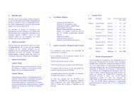
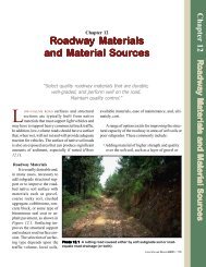
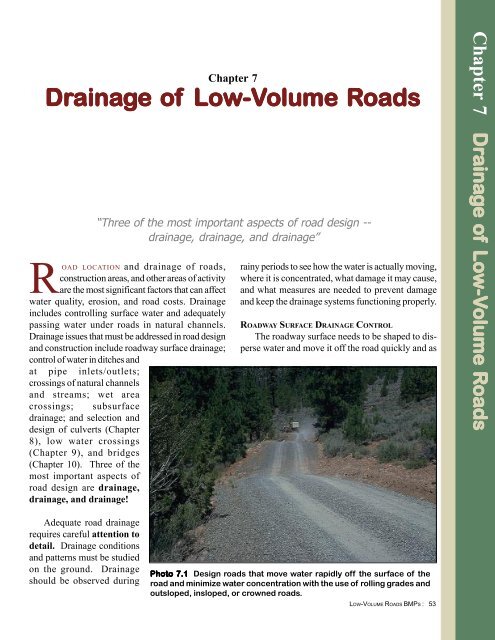
Photo 7.1 Design roads that move water rapidly <strong>of</strong>f the surface <strong>of</strong> the<br />
road and minimize water concentration with the use <strong>of</strong> rolling grades and<br />
outsloped, insloped, or crowned roads.<br />
LOW-VOLUME ROADS BMPS : 53
difficult to drain and can feel unsafe.<br />
Brush<br />
2:1<br />
2:1<br />
2:1<br />
3-5%<br />
Figur<br />
igure e 7.1 Typical road surface draina<br />
ainage e options.<br />
frequently as possible (Photo<br />
7.1). Water standing in potholes,<br />
ruts and sags will weaken the<br />
subgrade and accelerate damage.<br />
Water concentrated in ruts or kept<br />
on the road surface for long distances<br />
can accelerate erosion as<br />
well as wash <strong>of</strong>f the surface material.<br />
Steep road grades cause<br />
surface and ditch water to move<br />
rapidly, and make surface drainage<br />
difficult to control. Steep<br />
grades accelerate erosion unless<br />
surfaces are armored or water is<br />
dispersed or removed frequently.<br />
Crown Section<br />
Outslope Section<br />
3-5%<br />
3-5%<br />
3-5%<br />
Inslope with Ditch Section<br />
1:1<br />
2:1<br />
2:1<br />
1:1<br />
Armored<br />
Ditch<br />
need for an inside ditch, and minimizes<br />
costs. Outsloped roads<br />
with clay rich, slippery road surface<br />
materials <strong>of</strong>ten require rock<br />
surface stabilization or limited use<br />
during rainy periods to assure traffic<br />
safety. On road grades over 10<br />
to 12 percent and on steep hill<br />
slope areas, outsloped roads are<br />
Insloped roads best control<br />
the road surface water but concentrate<br />
water and thus require a<br />
system <strong>of</strong> ditches, cross-drains,<br />
and extra road width for the ditch.<br />
Cross-drains, using either rolling<br />
dips (broad-based dips) or culvert<br />
pipes, must be spaced frequently<br />
enough to remove all the expected<br />
road surface water before erosion<br />
occurs. The maximum recommended<br />
distances (listed in Table<br />
7.1) should be used for guidance<br />
on spacing <strong>of</strong> cross-drains and<br />
ditch relief structures. Specific locations<br />
should be determined in<br />
the field based upon actual water<br />
flow patterns, rainfall intensity,<br />
road surface erosion characteristics,<br />
and available erosion resistant<br />
outlet areas.<br />
Crown section roads are appropriate<br />
for higher standard, two<br />
lane roads on gentle grades. They<br />
also require a system <strong>of</strong> inside<br />
Roadway surface water<br />
should be controlled with positive<br />
drainage measures using<br />
outsloped, insloped, or crown<br />
sections <strong>of</strong> road, as shown in Figure<br />
7.1. Outsloped roads best<br />
disperse water and minimize road<br />
width, but may require roadway<br />
surface and fill slope stabilization.<br />
An outsloped road minimizes<br />
concentration <strong>of</strong> water, minimizes<br />
needed road width, avoids the<br />
LOW-VOLUME ROADS BMPS:54<br />
Photo 7.2 Use rolling dip (broad-based dip) cross-drains to move<br />
water <strong>of</strong>f the road surface efficiently and economically, without the<br />
use <strong>of</strong> culvert pipes. Rolling dip cross-drains are not susceptible to<br />
plugging.
Table 7.1<br />
Recommended Maximum Distance Between Rolling Dip<br />
or Culvert Cross-Drains (meters)<br />
<strong>Low</strong> to<br />
Road Grade % Non-Erosive soils (1) Erosive Soils (2)<br />
Table le 7.2<br />
0-3 120 75<br />
4-6 90 50<br />
7-9 75 40<br />
10-12 60 35<br />
12+ 50 30<br />
Recommended Water Bar Spacing (meters)<br />
Road/Trail <strong>Low</strong> to<br />
Grade % Non-Erosive soils (1) Erosive Soils (2)<br />
0-5 75 40<br />
6-10 60 30<br />
11-15 45 20<br />
16-20 35 15<br />
21-30 30 12<br />
30+ 15 10<br />
Note: (1) <strong>Low</strong> Erosion Soils = Coarse Rocky Soils, Gravel, and<br />
Some Clay<br />
(2) High Erosion Soils = Fine, Friable Soils, Silt, Fine<br />
Sands<br />
Adapted from Packer and Christensen (1964)<br />
& Copstead, Johansen, and Moll (1998)<br />
ditches and cross drains. It is difficult<br />
to create and maintain a<br />
crown on a narrow road, so generally<br />
insloped or outsloped road<br />
drainage is more effective for rural<br />
roads.<br />
Culvert cross-drains are used<br />
to move ditch water across the<br />
road. They are the most common<br />
type <strong>of</strong> road surface drainage, and<br />
are most appropriate for highstandard<br />
roads where a smooth<br />
road surface pr<strong>of</strong>ile is desired.<br />
However the pipes are expensive,<br />
and the relatively small culvert<br />
pipes used for cross-drains are<br />
suseptible to plugging and require<br />
cleaning.<br />
Rolling dip cross-drains<br />
(broad-based dips) are designed<br />
to pass slow traffic, while also dispersing<br />
surface water (Photo 7.2).<br />
Rolling dips usually cost less, require<br />
less maintenance, and are<br />
less likely to plug and fail than<br />
culvert pipes. Rolling dips are<br />
ideal on low volume, low to moderate<br />
speed roads (20-50 kph).<br />
Spacing is a function <strong>of</strong> road<br />
grade and soil type, as seen in<br />
Table 7.1. Other types <strong>of</strong> roadway<br />
surface cross-drain structures occasionally<br />
used include open top<br />
wood or metal flumes, and rubber<br />
water deflectors.<br />
Steep road grades are undesirable<br />
and problematic, but occasionally<br />
necessary. On grades up<br />
to 10%, cross-drains with culverts<br />
or rolling dips are easy to use. Between<br />
10 and 15%, frequently<br />
spaced culvert cross-drains work,<br />
<strong>of</strong>ten in conjunction with armored<br />
ditches. On grades over 15%, it<br />
is difficult to slow down the wa-<br />
LOW-VOLUME ROADS BMPS : 55
RECOMMENDED PRACTICES<br />
ROADWAY SURFACE<br />
DRAINAGE CONTROL<br />
• Design and construct roads<br />
so that they will move water<br />
rapidly <strong>of</strong>f the road surface<br />
to keep the surface drained<br />
and structurally sound.<br />
• Avoid steep road grades in<br />
excess <strong>of</strong> 12 to 18%. It is<br />
very difficult and expensive<br />
to properly control drainage<br />
on steep grades.<br />
• Maintain positive surface<br />
drainage with an outsloped,<br />
insloped, or crown roadway<br />
section using 3 - 5 % cross<br />
slopes (up to 5% is best)<br />
(Figure 7.1).<br />
• Roll grades or undulate the<br />
road pr<strong>of</strong>ile frequently to<br />
disperse water, particularly<br />
into and out <strong>of</strong> stream<br />
crossings (Figure 7.2a,<br />
Photo 7.1).<br />
• Use frequently spaced<br />
lead<strong>of</strong>f ditches (Figure 7.2b<br />
and Figure 7.8) to prevent<br />
accumulation <strong>of</strong> excessive<br />
water in the roadway<br />
ditches.<br />
• Use roadway cross-drain<br />
structures (either rolling<br />
dips, pipe culverts, or open<br />
top culverts (flumes)) to<br />
move water across the road<br />
from the inside ditch to the<br />
slope below the road. Space<br />
the cross-drain structures<br />
frequently enough to remove<br />
all surface water. Table 7.1<br />
gives recommended crossdrain<br />
spacing.<br />
• Protect cross-drain outlets<br />
with rock (riprap), brush, or<br />
logging slash to dissipate<br />
energy and prevent erosion,<br />
or locate the outlet <strong>of</strong> cross<br />
drains on stable, non-erosive<br />
soils, rock, or in well vegetated<br />
areas (Figure 7.2b).<br />
• Construct rolling dips<br />
rather than culvert crossdrains<br />
for typical, lowvolume,<br />
low speed roads<br />
with grades less than 12%.<br />
Construct rolling dips deep<br />
enough to provide adequate<br />
drainage, angled 0-25<br />
degrees from perpendicular<br />
to the road, with a 3-5%<br />
outslope, and long enough<br />
(15 to 60 meters) to pass<br />
vehicles and equipment (See<br />
Photo 7.2). In s<strong>of</strong>t soils,<br />
armor the mound and dip<br />
with gravel or rock, as well<br />
as the outlet <strong>of</strong> the dip<br />
(Figure 7.3).<br />
• Install culvert cross-drains<br />
with an angle <strong>of</strong> 0-30 degrees<br />
perpendicular to the<br />
road, using an outslope <strong>of</strong><br />
2% greater than the ditch<br />
grade to prevent plugging.<br />
(Figure 7.4). (See <strong>Chapter</strong><br />
8 for more information on<br />
culverts). Use culvert crossdrains<br />
on roads with an<br />
inside ditch and moderately<br />
fast vehicle speeds.<br />
• Construct water bars on<br />
infrequently used roads or<br />
closed roads to control<br />
surface run<strong>of</strong>f. Construct<br />
frequently spaced waterbars<br />
angled at 0-25 degrees with<br />
an outslope <strong>of</strong> 3-5% and a<br />
depth <strong>of</strong> 0.3 to 0.6 meters.<br />
Install water bars as shown<br />
in Figure 7.5. Spacing <strong>of</strong><br />
waterbars is shown in Table<br />
7.2.<br />
• Use catch water ditches<br />
(intercept ditches) across the<br />
natural ground above a cut<br />
slope only in areas with high<br />
intensity rainfall and overland<br />
flow. These ditches are<br />
useful to capture overland<br />
sheet flow before it pours<br />
over the cut slope and<br />
erodes or destabilizes the<br />
cut. However, be aware that<br />
catch water ditches are that<br />
are not properly maintained<br />
can become a counterproductive<br />
pool for water<br />
above the slope, increasing<br />
the probability <strong>of</strong> a slope<br />
failure.<br />
• Avoid the use <strong>of</strong> outside<br />
ditches, along the outside<br />
edge <strong>of</strong> the road, except in<br />
specific areas that must be<br />
protected from sheet flow<br />
<strong>of</strong>f the road surface. Preferably,<br />
use berms. Note that an<br />
outside ditch or berm necessitates<br />
additional road width.<br />
LOW-VOLUME ROADS BMPS:56
• Long sustained road grades<br />
that concentrate flows.<br />
• Discharging water onto<br />
PRACTICES TO AVOID<br />
erosive, unprotected soils.<br />
• “Eyeballing” grades in flat<br />
terrain. Use a clinometer,<br />
abney level, or survey<br />
equipment to ensure that<br />
you have proper slopes or<br />
grades.<br />
Figur<br />
igure 7.2<br />
Cut slope<br />
Fill slope<br />
Reinforced<br />
dip<br />
Ground slope<br />
a. Basic road surface drainage with outsloping, rolling grades, and reinforced dips.<br />
b. Basic road surface drainage with lead<strong>of</strong>f ditches and culvert cross-drains exiting into vegetation or a<br />
streamside buffer area. (Adapted from Montana State Univ. 1991)<br />
LOW-VOLUME ROADS BMPS : 57
Figur<br />
igure 7.3 Rolling (broad-based) dip cross-drains.<br />
Mound<br />
Inslope or<br />
Outslope<br />
Spacing 30 - 150 m<br />
0-25 o<br />
Riprap<br />
at Dip<br />
Exit<br />
Armored<br />
Dip<br />
a. Perspective View<br />
Dip<br />
Dip<br />
Average Road Grade<br />
2-5%<br />
Outslope<br />
2-5%<br />
Outslope<br />
b. Pr<strong>of</strong>ile<br />
Armor Dip and Mound<br />
Surface as Needed with<br />
5-15 cm Aggregate<br />
For Insloped Road – Slope to Depth<br />
<strong>of</strong> Inside Ditch<br />
For Outsloped Road – 3-5 cm Deep<br />
or Match Depth <strong>of</strong> Inside Ditch at<br />
Entrance – 15-30 cm Deep at Exit<br />
Road Grade<br />
2-12%<br />
Reverse Slope<br />
3-6%<br />
Average Road Grade<br />
8-30m 7-12m<br />
8-30m<br />
c. Rolling Dip Pr<strong>of</strong>ile Detail<br />
LOW-VOLUME ROADS BMPS:58
○ ○ ○ ○ ○ ○ ○ ○ ○ ○ ○ ○ ○ ○ ○ ○ ○ ○ ○<br />
Figur<br />
igure 7.4 Culvert cross-drains.<br />
Inlet<br />
Structure<br />
as Needed<br />
Spacing 30–150 m<br />
Berm<br />
0 o -30 o<br />
Place Outlet Pipe at<br />
Natural Ground<br />
Level or Riprap<br />
Armor the Fill<br />
Material.<br />
Figur<br />
igure e 7.5 Water bar construction. (Adapted from Wisonsin’s Forestry Best Management Practices<br />
for Water Quality. 1995, Publication FR093, Wisconsin Department <strong>of</strong> Natural Resources)<br />
Berm Tied into<br />
Embankment<br />
Spacing 10–75 m<br />
0-25 o<br />
Exit onto Stable<br />
or Armored<br />
Ground<br />
a. Perspective View<br />
30-60 cm 30-60 cm<br />
Road Grade<br />
1 - 2 m 1 - 2 m 1 - 2 m<br />
b. Cross-Section<br />
LOW-VOLUME ROADS BMPS : 59
CONTROL AT INLETS AND OUTLETS<br />
OF CROSS-DRAINS AND DITCHES<br />
Water should be controlled,<br />
directed, or have energy dissipated<br />
at the inlet and outlet <strong>of</strong><br />
culverts, rolling dips, or other<br />
cross-drainage structures. This<br />
can ensure that water and debris<br />
enters the cross-drain efficiently<br />
without plugging, and that it exits<br />
the cross-drain without damaging<br />
the structure or causing erosion<br />
at the outlet.<br />
Photo 7.3 Use masonry, concrete, or metal inlet structures to<br />
control water in the ditch, direct the water into the cross-drain pipe,<br />
and prevent ditch down-cutting.<br />
ter or remove it from the road<br />
surface rapidly. On such steep<br />
grades, it is best to use frequently<br />
spaced cross-drain culverts, with<br />
armored ditches. Also, the road<br />
surface will need armoring or surfacing<br />
with some form <strong>of</strong> pavement<br />
to resist erosion. For seasonal<br />
or low use roads, interim<br />
drivable waterbars could also be<br />
constructed.<br />
Water bars are used to control<br />
drainage on closed or inactive<br />
roads, 4-wheel drive roads,<br />
skid roads, and skid trails. Water<br />
bars are frequently spaced (see<br />
Table 7.2) for maximum erosion<br />
control and can be shaped to pass<br />
high clearance vehicles or to block<br />
traffic.<br />
Culvert inlet structures (drop<br />
inlets) are usually placed in the inside<br />
ditchline at the location <strong>of</strong> a<br />
culvert cross-drain. They are commonly<br />
constructed <strong>of</strong> concrete,<br />
masonry (Photo 7.3), or from<br />
round metal pipe, as seen in Figure<br />
7.6. They are typically used<br />
where the ditch is eroding and<br />
downcutting, so that the structure<br />
controls the ditch elevation. Inlet<br />
structures are also useful to<br />
change the direction <strong>of</strong> water<br />
flowing in the ditch, particularly<br />
on steep grades, and they can help<br />
stabilize the cut bank behind the<br />
pipe inlet.<br />
Photo 7.4 Add outlet protection and/or energy dissipators to prevent<br />
erosion and the formation <strong>of</strong> gullies.<br />
LOW-VOLUME ROADS BMPS:60<br />
The outlet <strong>of</strong> pipes and dips<br />
are ideally located in a stable, nonerosive<br />
soil area or in a well-vegetated<br />
or rocky area. The accelerated<br />
velocity <strong>of</strong> water leaving a<br />
roadway can cause severe erosion<br />
or gullying if discharged directly<br />
onto erosive soils (Photo 7.4).<br />
The pipe, dip, or drain outlet area<br />
can be stabilized, and the energy<br />
<strong>of</strong> the water dissipated, by discharging<br />
the water onto 1-2 cubic<br />
meters <strong>of</strong> a graded rock riprap,<br />
as seen in Figure 7.7. Other energy<br />
dissipation measures include<br />
the use <strong>of</strong> stilling basins, rein-
slow down the velocity <strong>of</strong> water,<br />
as shown in Figure 7.8. Ditches<br />
are commonly armored with grass,<br />
erosion control matting, rock, or<br />
masonry /concrete paving (Photo<br />
7.6). Grasses can resist flow velocities<br />
to 1-2 meters per second.<br />
A durable armoring such as graded<br />
rock riprap or concrete is recommended<br />
on grades over 5 percent<br />
in erosive soils or for velocities<br />
over a few meters per second.<br />
Photo 7.5 Protect the outlet <strong>of</strong> culvert pipe and rolling dip crossdrains<br />
with riprap or a masonry splash apron, or choose areas <strong>of</strong><br />
bedrock or dense vegetation.<br />
forced splash aprons, or use <strong>of</strong><br />
dense vegetation or bedrock<br />
(Photo 7.5).<br />
Ditches on steep road grades,<br />
RECOMMENDED PRACTICES<br />
CONTROL AT INLETS & OUTLETS<br />
• When ditch grade control is<br />
needed, use drop inlet structures<br />
with culvert cross-drains<br />
to prevent ditch down-cutting<br />
or where space is limited<br />
against the cut bank (Figure<br />
7.6). Alternately, use catch<br />
basins excavated into firm<br />
soil.<br />
• Discharge culverts and crossdrain<br />
dips at natural ground<br />
level, on firm, non-erosive<br />
soil or in rocky or brushy<br />
areas. If discharged on the fill<br />
slopes, armor outlets with<br />
riprap or logging slash, or use<br />
down-drain structures. (Figures<br />
7.3, 7.4, 7.7 and Figure<br />
8.1). Extend the pipe 0.5 to<br />
in erosive soils, and with flow velocities<br />
over one meter per second<br />
may require armoring or the<br />
use <strong>of</strong> small ditch dike or dam<br />
structures placed in the ditch to<br />
1.0 meters beyond the toe <strong>of</strong><br />
the fill slope to prevent<br />
erosion <strong>of</strong> the fill material.<br />
• In erosive soils, armor<br />
roadway ditches and lead<strong>of</strong>f<br />
ditches with rock riprap<br />
(Photo 7.7), masonry,<br />
concrete lining or, at a<br />
minimum, grasses. Ditch<br />
dike structures can also be<br />
used to dissipate energy and<br />
control ditch erosion.<br />
(Figure 7.8).<br />
• Discharge roadway drains in<br />
an area with infiltration<br />
capability or into filter strips<br />
to trap sediment before it<br />
reaches a waterway. Keep<br />
the road and streams hydrologically<br />
“disconnected.”<br />
Ditch dikes will prevent ditch<br />
erosion, and dikes can serve to<br />
catch sediment, but they require<br />
maintenanceneed in that they need<br />
to be periodically cleaned out.<br />
Common ditch dike construction<br />
materials include loose rock, masonry,<br />
concrete, bamboo, and<br />
wooden posts. Each dike structure<br />
should be keyed into the banks <strong>of</strong><br />
the ditch and a notch is needed<br />
over each structure to keep the<br />
flow in the middle <strong>of</strong> the ditch.<br />
PRACTICES TO<br />
AVOID<br />
• Discharging a cross-drain<br />
pipe or dip onto any unprotected<br />
fill slope or barren,<br />
erosive soil.<br />
• Discharging cross-drain<br />
pipes mid-height on a fill<br />
slope.<br />
• Discharging cross-drain<br />
pipes or dips onto unstable<br />
natural slopes.<br />
LOW-VOLUME ROADS BMPS : 61
Photo 7.6 Armor ditches with vegetation, rock, masonry, or concrete to<br />
resist ditch erosion and carry the water to a stable exit point.<br />
Figur<br />
igure e 7.6 Typical drop inlet structure types (with culvert cross-drains).<br />
Use drop inlet structure to control the level <strong>of</strong> water,<br />
turn water into the pipe, and prevent downcutting and erosion <strong>of</strong> the ditch.<br />
Roadbed surface<br />
Grass for<br />
Erosion<br />
Control<br />
Energy<br />
Dissipation<br />
with Riprap,<br />
Concrete<br />
Apron or<br />
Splash pool<br />
with water<br />
General Information<br />
Bottom <strong>of</strong> ditch<br />
Roadbed Surface<br />
Slope<br />
45 cm<br />
Slope<br />
30 cm<br />
Window<br />
45 cm<br />
"1 m<br />
Drop inlet<br />
structure<br />
Culvert Pipe (30-60 cm diameter)<br />
Sand trap<br />
30 cm<br />
0.6-1.2 m<br />
Masonry<br />
LOW-VOLUME ROADS BMPS:62<br />
Design and Installation Detail<br />
90 cm<br />
Metal
Figur<br />
igure 7.7 Culvert outlet protection.<br />
Fill Slope<br />
Rocks:<br />
15-50 kg<br />
5% greater than 25 kg<br />
0.5 m<br />
minimum<br />
1-2 m<br />
15-30 cm<br />
minimum<br />
depth<br />
Ground Line<br />
Photo 7.7 A rock armored ditch and metal drop inlet to control the<br />
water and prevent down-cutting <strong>of</strong> the ditch.<br />
LOW-VOLUME ROADS BMPS : 63
Figur<br />
igure 7.8 Ditches and ditch armoring.<br />
Roadway<br />
Exit ditch in<br />
stable, vegetated<br />
area<br />
Flow<br />
Excavate ditch into firm soil.<br />
Armor ditch in erosive soil areas.<br />
a. Ditch Layout and Lead<strong>of</strong>f (Adapted from Wisconsin’s Forestry Best Management Practices for Water<br />
Quality, 1995)<br />
Insloped Roadbed<br />
Armor the ditch with<br />
rock, masonry or grass<br />
1 m<br />
Cut slope<br />
30 cm min.<br />
b. Typical Ditch Armoring and Shape<br />
Cut slope<br />
Roadway<br />
Ditch dikes made <strong>of</strong> rock or<br />
wood to reduce flow velocity<br />
Weir shape to keep<br />
flow mid-ditch<br />
c. Use <strong>of</strong> Ditch Dikes<br />
LOW-VOLUME ROADS BMPS:64
NATURAL STREAM CROSSINGS<br />
Road crossings <strong>of</strong> natural<br />
drainage channels and streams require<br />
hydrologic and hydraulic design<br />
expertise to determine the<br />
proper size and type <strong>of</strong> structure,<br />
as discussed in <strong>Chapter</strong>s 5 and 6.<br />
Structures for small drainages can<br />
be sized using Table 8.1. The<br />
choice <strong>of</strong> structure includes culvert<br />
pipes, arch or box culverts,<br />
low water fords, or bridges, as<br />
shown in Figure 7.9.<br />
nel scour, traffic delays, and costly<br />
repairs if a structure fails. Also,<br />
structures can greatly impact fish,<br />
as well as other aquatic species,<br />
at all stages <strong>of</strong> life. Stream crossings<br />
should be as short as possible<br />
and cross perpendicular to the<br />
channel (Photo 7.8). The road and<br />
ditches should be armored, ditches<br />
should divert surface water before<br />
it reaches the stream channel, and<br />
construction should minimize the<br />
area <strong>of</strong> disturbance, as shown in<br />
Figure 7.10. Large drainage<br />
crossings should receive site-specific<br />
analysis and design input, ideally<br />
by an experienced hydraulic<br />
engineer and other specialists.<br />
In drainages with uncertain<br />
flow values, large quantities <strong>of</strong> debris<br />
in the channel, or on sites with<br />
existing undersized pipes, there is<br />
a high risk <strong>of</strong> a culvert pipe plugging<br />
and the site washing out or<br />
failing. In such areas, or in particularly<br />
sensitive watersheds,<br />
overflow protection is desirable.<br />
A low point in the fill and an armored<br />
overflow “spillway,” as<br />
shown in Figures 7.11a & b, will<br />
protect the fill and keep the flow<br />
in the same drainage, thus reducing<br />
diversion potential and usually<br />
preventing a failure. A plugged<br />
pipe that diverts the stream water<br />
down the road can cause a great<br />
deal <strong>of</strong> <strong>of</strong>f-site damage or gullying<br />
or cause landslides, as seen in<br />
Figures 7.11c & d. Overflow<br />
structures should not be used as a<br />
substitute for good hydraulic design,<br />
but they can <strong>of</strong>fer “cheap<br />
insurance” against failure at culvert<br />
crossings.<br />
Figur<br />
igure e 7.9 Structural options for crossing natural streams. (Adapted from Ontario Ministry <strong>of</strong> Natural<br />
Resources, 1988)<br />
Because drainage crossings<br />
are at areas <strong>of</strong> running water, they<br />
can be costly to construct and can<br />
have major negative impacts on<br />
water quality. Impacts from improper<br />
design or installation <strong>of</strong><br />
structures can include degraded<br />
water quality, bank erosion, chana.<br />
Bridge b. <strong>Low</strong>-Water Crossing<br />
c. Arch Pipe d. Culvert with Single or Multiple Pipes<br />
LOW-VOLUME ROADS BMPS : 65
NATURAL STREAM CROSSINGS<br />
• Use drainage structures that<br />
best conform to the natural<br />
channel and that are as wide<br />
as the active stream channel<br />
(bankfull width). Minimize<br />
natural channel changes and<br />
the amount <strong>of</strong> excavation or<br />
fill in the channel.<br />
• Limit construction activity to<br />
periods <strong>of</strong> low flow in live<br />
streams. Minimize use <strong>of</strong><br />
equipment in the stream.<br />
Stay out <strong>of</strong> the stream!<br />
• Design structures and use<br />
construction practices that<br />
minimize impacts on fish and<br />
other aquatic species or that<br />
can enhance fish passage.<br />
• Cross drainage channels as<br />
infrequently as possible.<br />
When necessary, cross<br />
streams at right angles<br />
except where prevented by<br />
terrain features (Figure<br />
7.10).<br />
• Keep approaches to stream<br />
crossings to as gentle a<br />
RECOMMENDED PRACTICES<br />
grade as practical. Roll<br />
grades into and out <strong>of</strong> the<br />
crossing to disperse water.<br />
• Stabilize disturbed soil<br />
around crossings soon after<br />
construction. Remove or<br />
protect fill material placed in<br />
the channel and floodplain.<br />
• Use bridges, low-water fords<br />
or improved fords, and large<br />
arch pipes with natural<br />
stream bottoms wherever<br />
possible to maximize flow<br />
capacity, minimize the<br />
possibility <strong>of</strong> a plugged pipe,<br />
and minimize impacts on<br />
aquatic species.<br />
• Locate crossings where the<br />
stream channel is straight,<br />
stable, and not changing<br />
shape. Bedrock locations are<br />
desirable for concrete<br />
structures.<br />
• For overflow protection,<br />
construct fills over culverts<br />
with an armored low point<br />
near the pipe in low fills or<br />
add an armored rolling dip<br />
on native ground just beyond<br />
a large fill to return<br />
water to the drainage and<br />
prevent <strong>of</strong>f-site damage<br />
(Figure 7.11).<br />
• Stabilize roadway approaches<br />
to bridges, fords,<br />
or culvert crossings with<br />
gravel, rock, or other<br />
suitable material to reduce<br />
road surface sediment<br />
from entering the stream<br />
(Figure 7.12). Install<br />
cross-drains on both sides<br />
<strong>of</strong> a crossing to prevent<br />
road and ditch run<strong>of</strong>f from<br />
entering the drainage<br />
channel.<br />
• Construct bridges and<br />
culvert fills higher than the<br />
road approach to prevent<br />
road surface run<strong>of</strong>f from<br />
draining directly into the<br />
stream -- but ONLY if<br />
likelihood <strong>of</strong> culvert<br />
failure is VERY small.<br />
(Figure 7.13). Typically,<br />
the crossing should be<br />
designed to minimize the<br />
amount <strong>of</strong> fill.<br />
PRACTICES TO AVOID<br />
• Working with equipment in<br />
an unprotected natural<br />
streambed.<br />
• Locating stream crossings<br />
in sinuous or unstable<br />
channels.<br />
• Adversely impacting fisheries<br />
with a stream crossing<br />
structure.<br />
• Allowing run<strong>of</strong>f from roadside<br />
ditches to flow directly<br />
into streams.<br />
LOW-VOLUME ROADS BMPS:66
Figur<br />
igure 7.10 Natural drainage crossings. Minimize the area <strong>of</strong> disturbance with a perpendicular<br />
stream crossing alignment, and armor the roadway surface.<br />
Poor Stream Crossing<br />
Better Stream Crossing<br />
Crossdrain<br />
Road<br />
Road<br />
Road<br />
Large<br />
cutslope<br />
area<br />
Road<br />
Cutslopes<br />
Crossings near parallel to the drainage cause a<br />
large disturbed area in the channel, streambank,<br />
and approach cuts.<br />
<strong>Drainage</strong> crossings perpendicular to the creek<br />
minimize the area <strong>of</strong> disturbance. Armor the<br />
stream crossing and roadway surface.<br />
Photo 7.8 Avoid natural drainage crossings that are broad and that are<br />
not perpendicular to the drainage. Stay out <strong>of</strong> the stream! This broad<br />
channel is a good site for a vented ford.<br />
LOW-VOLUME ROADS BMPS : 67
Figur<br />
igure 7.11<br />
Culvert Installed with Protection using an Armored<br />
Overflow Dip to Prevent Washout and Fill Failure<br />
A<br />
B<br />
C<br />
D<br />
(A) Roadway Cross Drain (Dip)<br />
(B) Culvert<br />
(C) Overflow Protection Dip<br />
(D) High point in the road pr<strong>of</strong>ile<br />
A<br />
Road Pr<strong>of</strong>ile Across the <strong>Drainage</strong> and Dip<br />
Fill<br />
B<br />
D<br />
C<br />
Armored dip<br />
Pipe<br />
a. Overflow dip protection at a fill stream crossing. (Adapted from Weaver and Hagans, 1994)<br />
LOW-VOLUME ROADS BMPS:68
Figur<br />
igure 7.11 (continued)<br />
Good Installation<br />
b. Armored dip over a low fill to prevent stream diversion.<br />
Poor Installation<br />
c. Sketch <strong>of</strong> a stream diverted down the road, forming a new channel.<br />
Plugged Culvert<br />
Abandoned<br />
Channel<br />
Slumping<br />
New Channel<br />
in a Gully<br />
d. Consequence <strong>of</strong> stream diversion out <strong>of</strong> its natural channel. (Adapted from M. Furniss, 1997)<br />
LOW-VOLUME ROADS BMPS : 69
Figur<br />
igure 7.12 Protection measures at stream crossings.<br />
15-30 m stone<br />
or gravel<br />
approach<br />
Hardened<br />
stream<br />
bottom<br />
Gravel<br />
or stone<br />
surfacing<br />
Ditch<br />
Rolling dip<br />
or<br />
cross-drain<br />
Riprap (rock)<br />
Debris<br />
Armor or stabilize the actual stream crossing (ford), add surfacing to the roadbed, and<br />
drain water <strong>of</strong>f the road surface before reaching the crossing. Set stream channel<br />
armoring at the elevation <strong>of</strong> the natural stream bottom.<br />
Figur<br />
igure e 7.13 High point over the crossing. (Adapted from Wisconsin’s Forestry Best Management<br />
Practices for Water Quality, 1995)<br />
Road<br />
If a plugging failure is unlikely to occur, place fill directly over a culvert higher than<br />
the road approach to prevent surface road run<strong>of</strong>f from draining toward the crossing<br />
structure and into the stream.<br />
LOW-VOLUME ROADS BMPS:70
WET AREAS AND MEADOW<br />
CROSSINGS, USE OF UNDERDRAINS<br />
Road crossings in wet areas,<br />
including damp meadows,<br />
swamps, high groundwater areas,<br />
and spring sources are problematic<br />
and undesirable. Wet areas are<br />
ecologically valuable and difficult<br />
for road building, logging, or other<br />
operations. Soils in these areas are<br />
<strong>of</strong>ten weak and require considerable<br />
subgrade reinforcement.<br />
<strong>Drainage</strong> measures are expensive<br />
and may have limited effectiveness.<br />
Wet areas should be<br />
avoided!<br />
If wet areas must be crossed<br />
and cannot be avoided, special<br />
drainage or construction methods<br />
should be used to reduce impacts<br />
from the crossing. They include<br />
multiple drainage pipes (Photo<br />
7.9) or coarse permeable rock fill<br />
to keep the flow dispersed,<br />
subgrade reinforcement with<br />
coarse permeable rock, grade control,<br />
and the use <strong>of</strong> filter layers and<br />
geotextiles, as shown in Figure<br />
7.14. The objective is to maintain<br />
the natural groundwater level and<br />
flow patterns dispersed across the<br />
meadow and, at the same time,<br />
provide for a stable, dry roadway<br />
surface.<br />
can provide some reinforcement<br />
strength as well as provide separation<br />
to keep aggregate or other<br />
materials from punching into the<br />
weak subgrade.<br />
Subsurface drainage, through<br />
use <strong>of</strong> underdrains or aggregate<br />
filter blankets, is commonly used<br />
along a road in localized wet or<br />
spring areas, such as a wet cut<br />
bank with seepage, to specifically<br />
remove the groundwater and<br />
keep the roadway subgrade dry.<br />
A typical underdrain design uses<br />
an interceptor trench 1-2 meters<br />
deep and backfilled with drain<br />
rock, as shown in Figure 7.16.<br />
Subsurface drainage is typically<br />
needed in local wet areas and is<br />
much more cost-effective than<br />
adding a thick structural section<br />
to the road or making frequent<br />
road repairs. Design and filtration<br />
requirements for underdrains are<br />
discussed in <strong>Chapter</strong> 6 and other<br />
references.<br />
In extensive swamp or wet areas,<br />
subsurface drainage will <strong>of</strong>ten<br />
not be effective. Here, either<br />
the roadway platform needs to be<br />
raised well above the water table,<br />
such as with a turnpike roadway<br />
section, or the surfacing thickness<br />
design may be based upon wet,<br />
weak subgrade conditions that<br />
will require a relatively thick<br />
structural section. A thick aggregate<br />
layer is commonly used, with<br />
the thickness based upon the<br />
strength <strong>of</strong> the soil and anticipated<br />
traffic loads.<br />
PRACTICES<br />
TO AVOID<br />
• Crossing wet areas unnecessarily.<br />
• Concentrating water flow<br />
in meadows or changing<br />
the natural surface and<br />
subsurface flow patterns.<br />
• Placing culverts below the<br />
meadow surface elevation.<br />
Local wet areas can be temporarily<br />
crossed, or “bridged”<br />
over, using logs, landing mats,<br />
tires, aggregate, and so on. (see<br />
Figure 7.15). Ideally, the temporary<br />
structure will be separated<br />
from the wet area with a layer <strong>of</strong><br />
geotextile. The geotextile helps facilitate<br />
removal <strong>of</strong> the temporary<br />
material and minimizes damage to<br />
the site. Also, a layer <strong>of</strong> geotextile<br />
Photo 7.9 Avoid crossing wet meadow areas. When necessary to<br />
cross, use multiple drainage pipes to keep water flow dispersed<br />
across the meadow.<br />
LOW-VOLUME ROADS BMPS : 71
Roadway<br />
Figur<br />
igure 7.14 Wet meadow road crossing options. (From Managing <strong>Roads</strong> for Wet Meadow Ecostream<br />
Recovery by Wm. Zeedyk, 1996)<br />
PERMEABLE FILL WITH CULVERTS<br />
(for periodic high flows on flood plains and meadows)<br />
a.<br />
Berm<br />
Culverts<br />
Flow<br />
Flow<br />
Meadow<br />
b.<br />
Roadway<br />
Meadow<br />
surface<br />
Berm<br />
Geotextile<br />
Flow<br />
10-15 cm minus rock<br />
c.<br />
Geotextile<br />
ROCK FILL WITHOUT CULVERTS<br />
(for minimal overland flow)<br />
Roadway<br />
15 cm Thick<br />
Aggregate<br />
Base Course<br />
15 cm Minus Rock<br />
Course Placed Approx.<br />
30 cm Thick<br />
Flow<br />
Flow<br />
LOW-VOLUME ROADS BMPS:72
Figur<br />
igure 7.15 Pole or plastic pipe fords for wet area and bog crossings. Pole fords must be removed<br />
immediately after use or before the upstream end becomes clogged with debris and impedes stream<br />
flow. (Adapted from Vermont Department <strong>of</strong> Forests, Parks and Recreation, 1987)<br />
WET AREAS AND MEADOW<br />
CROSSINGS, UNDERDRAINS<br />
• For permanent road crossings<br />
<strong>of</strong> meadows and wetlands,<br />
maintain the natural<br />
groundwater flow patterns<br />
by the use <strong>of</strong> multiple pipes<br />
set at meadow level to<br />
spread out any overland<br />
flow (See Photo 7.9).<br />
Alternatively, a coarse,<br />
permeable rock fill can be<br />
used where overland (surface)<br />
flow is minimal (see<br />
Figure 7.14).<br />
• In areas with local wet spots<br />
and limited road use, reinforce<br />
the roadway with at<br />
least 10-30 cm <strong>of</strong> coarse<br />
graded rock or a very coarse<br />
granular soil. Ideally, separate<br />
the coarse rock and wet<br />
RECOMMENDED PRACTICES<br />
soil with a filter layer <strong>of</strong><br />
geotextile or gravel.<br />
• For temporary crossing <strong>of</strong><br />
small, wet drainages or<br />
swamps, “corduroy” the<br />
road with layers <strong>of</strong> logs<br />
placed perpendicular to the<br />
road and capped with a soil<br />
or gravel driving surface.<br />
PVC pipe, landing mats,<br />
wood planks, tire mats and<br />
other materials have also<br />
been used (see Figure 7.15).<br />
Place a layer <strong>of</strong> geotextile<br />
between the saturated soil<br />
and logs or other material<br />
for additional support and to<br />
separate the materials.<br />
Remove logs from any<br />
natural drainage channel<br />
before the rainy season (see<br />
Photo 8.8). A layer <strong>of</strong> chainlink<br />
fencing or wire under<br />
the logs can help facilitate<br />
removal <strong>of</strong> the logs.<br />
• In spring areas, use drainage<br />
measures such as<br />
underdrains or filter blankets<br />
to remove local groundwater<br />
and keep the road<br />
subgrade dry (Figure 7.16,<br />
Photo 7.10).<br />
• Use underdrains behind<br />
retaining structures to<br />
prevent saturation <strong>of</strong> the<br />
backfill. Use underdrains or<br />
filter blankets behind fills<br />
(embankments) placed over<br />
springs or wet areas to<br />
isolate the fill material and<br />
prevent saturation and<br />
possible subsequent fill<br />
failure.<br />
LOW-VOLUME ROADS BMPS : 73
Figur<br />
igure 7.16 Typical road underdrain used to remove subsurface water.<br />
Cut<br />
15 cm Cap <strong>of</strong><br />
Impermeable Soil<br />
Roadbed<br />
Ditch<br />
Geotextile Enveloping the<br />
Filter Material<br />
Ground Water<br />
Variable<br />
Depth<br />
(Typically<br />
+/- 1.5 m<br />
Deep)<br />
5-10 cm<br />
60 cm<br />
min.<br />
Filter Material, Permeable Sandy<br />
Gravel, Well Graded<br />
NOTE: With Geotextile, use clean,<br />
coarse gravel.<br />
Without Geotextile, use fine, clean<br />
sand.<br />
Pipe, Perforated<br />
15 cm dia. (min)<br />
Photo 7.10 Use subdrains or filter blankets when necessary to remove groundwater<br />
from the roadway subgrade in local wet or spring areas. Note that this design<br />
needs a second layer <strong>of</strong> geotextile between the s<strong>of</strong>t subgrade soil and the coarse<br />
filter rock to keep the rock clean.<br />
LOW-VOLUME ROADS BMPS:74