
You also want an ePaper? Increase the reach of your titles
YUMPU automatically turns print PDFs into web optimized ePapers that Google loves.
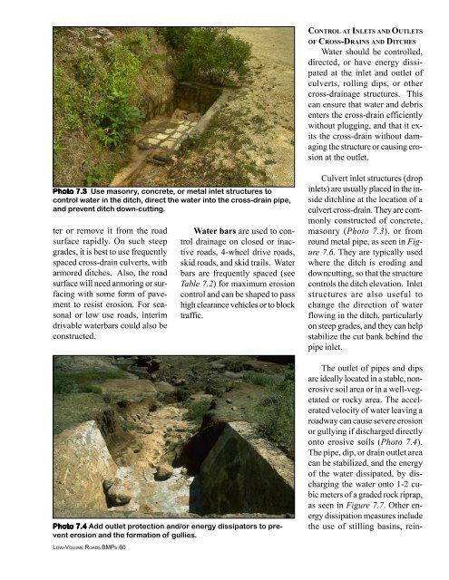
CONTROL AT INLETS AND OUTLETS<br />
OF CROSS-DRAINS AND DITCHES<br />
Water should be controlled,<br />
directed, or have energy dissipated<br />
at the inlet and outlet <strong>of</strong><br />
culverts, rolling dips, or other<br />
cross-drainage structures. This<br />
can ensure that water and debris<br />
enters the cross-drain efficiently<br />
without plugging, and that it exits<br />
the cross-drain without damaging<br />
the structure or causing erosion<br />
at the outlet.<br />
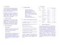
Photo 7.3 Use masonry, concrete, or metal inlet structures to<br />
control water in the ditch, direct the water into the cross-drain pipe,<br />
and prevent ditch down-cutting.<br />
ter or remove it from the road<br />
surface rapidly. On such steep<br />
grades, it is best to use frequently<br />
spaced cross-drain culverts, with<br />
armored ditches. Also, the road<br />
surface will need armoring or surfacing<br />
with some form <strong>of</strong> pavement<br />
to resist erosion. For seasonal<br />
or low use roads, interim<br />
drivable waterbars could also be<br />
constructed.<br />
Water bars are used to control<br />
drainage on closed or inactive<br />
roads, 4-wheel drive roads,<br />
skid roads, and skid trails. Water<br />
bars are frequently spaced (see<br />
Table 7.2) for maximum erosion<br />
control and can be shaped to pass<br />
high clearance vehicles or to block<br />
traffic.<br />
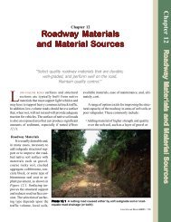
Culvert inlet structures (drop<br />
inlets) are usually placed in the inside<br />
ditchline at the location <strong>of</strong> a<br />
culvert cross-drain. They are commonly<br />
constructed <strong>of</strong> concrete,<br />
masonry (Photo 7.3), or from<br />
round metal pipe, as seen in Figure<br />
7.6. They are typically used<br />
where the ditch is eroding and<br />
downcutting, so that the structure<br />
controls the ditch elevation. Inlet<br />
structures are also useful to<br />
change the direction <strong>of</strong> water<br />
flowing in the ditch, particularly<br />
on steep grades, and they can help<br />
stabilize the cut bank behind the<br />
pipe inlet.<br />
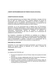
Photo 7.4 Add outlet protection and/or energy dissipators to prevent<br />
erosion and the formation <strong>of</strong> gullies.<br />
LOW-VOLUME ROADS BMPS:60<br />
The outlet <strong>of</strong> pipes and dips<br />
are ideally located in a stable, nonerosive<br />
soil area or in a well-vegetated<br />
or rocky area. The accelerated<br />
velocity <strong>of</strong> water leaving a<br />
roadway can cause severe erosion<br />
or gullying if discharged directly<br />
onto erosive soils (Photo 7.4).<br />
The pipe, dip, or drain outlet area<br />
can be stabilized, and the energy<br />
<strong>of</strong> the water dissipated, by discharging<br />
the water onto 1-2 cubic<br />
meters <strong>of</strong> a graded rock riprap,<br />
as seen in Figure 7.7. Other energy<br />
dissipation measures include<br />
the use <strong>of</strong> stilling basins, rein-