Ethernet Technology
Ethernet Technology
Ethernet Technology

Create successful ePaper yourself
Turn your PDF publications into a flip-book with our unique Google optimized e-Paper software.
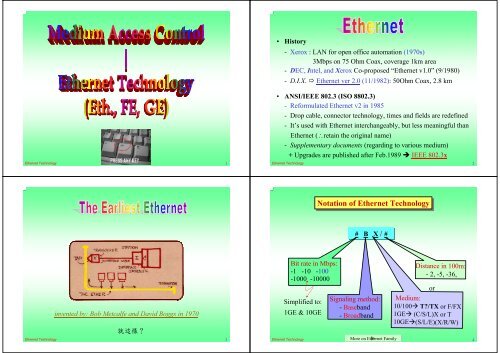
• History<br />
- Xerox : LAN for open office automation (1970s)<br />
3Mbps on 75 Ohm Coax, coverage 1km area<br />
- DEC, Intel, and Xerox Co-proposed “<strong>Ethernet</strong> v1.0” (9/1980)<br />
- D.I.X. <strong>Ethernet</strong> ver 2.0 (11/1982): 50Ohm Coax, 2.8 km<br />
• ANSI/IEEE IEEE 802.3 (ISO 8802.3)<br />
- Reformulated <strong>Ethernet</strong> v2 in 1985<br />
- Drop cable, connector technology, times and fields are redefined<br />
- It’s used with <strong>Ethernet</strong> interchangeably, but less meaningful than<br />
<strong>Ethernet</strong> (retain the original name)<br />
- Supplementary documents (regarding to various medium)<br />
+ Upgrades are published after Feb.1989 IEEE 802.3x<br />
<strong>Ethernet</strong> <strong>Technology</strong> 1 <strong>Ethernet</strong> <strong>Technology</strong> 2<br />
Notation of of <strong>Ethernet</strong> <strong>Technology</strong><br />
# B X / #<br />
invented by: Bob Metcalfe and David Boggs in 1970<br />
<br />
<strong>Ethernet</strong> <strong>Technology</strong> 3<br />
Bit rate in Mbps:<br />
-1 -10 -100<br />
-1000 -10000<br />
Simplified to:<br />
1GE & 10GE<br />
Signaling method:<br />
- Baseband<br />
- Broadband<br />
Medium:<br />
Distance in 100m:<br />
- 2, -5, -36,<br />
10/100 T?/TX or F/FX<br />
1GE (C/S/L)X or T<br />
10GE(S/L/E)(X/R/W)<br />
<strong>Ethernet</strong> <strong>Technology</strong> More on <strong>Ethernet</strong> Family<br />
4<br />
or
Bus Topology -- 10Base2/5/36<br />
• Connecting nodes via (tap to) coaxial cable<br />
• Transmission and receiving over the same media (line)<br />
• Basic configuration (Ex: A 10Base5 segment = a coax) :<br />
Terminator<br />
500 <br />
Coaxial Cable<br />
<br />
Transceiver<br />
node<br />
50 <br />
<br />
100 NPS<br />
MSL<br />
DBT<br />
Multiple of 2.5m<br />
TRL<br />
tap<br />
Terminator<br />
<br />
Extension ?<br />
MES<br />
Explanation of the Abbreviations<br />
TRL ~ Transceiver’s cable Length<br />
DBN ~ Distance Between Nodes<br />
NPS ~ Nodes Per Segment<br />
MSL ~ Maximum Segment Length<br />
MES ~ Maximum Extendable Segments<br />
• Important parameters: TRL, DBT, NPS, MSL, and MND.<br />
<strong>Ethernet</strong> <strong>Technology</strong> 5<br />
<strong>Ethernet</strong> <strong>Technology</strong> 6<br />
Star/Tree Topology -- 10BaseT/F, 1Base5<br />
Transmitting and Receiving Frames<br />
• Connecting nodes via (tap to) UTP / FO<br />
• Transmission and receiving over separate media (line)<br />
• Basic configuration (Ex: one 10BaseT segment)<br />
A<br />
B<br />
segment<br />
Hub<br />
Number of ports/hub<br />
segment<br />
Bus<br />
Hub - multiple repeater<br />
()<br />
All stations are in the same “collision domain”<br />
Physically a star,<br />
logically a bus<br />
A<br />
B<br />
Length (PC/Hub-to-PC/Hub) = a “segment” ; 100m, max<br />
<strong>Ethernet</strong> <strong>Technology</strong> 7<br />
Star<br />
<strong>Ethernet</strong> <strong>Technology</strong> 8
IEEE 802.3 (MAC) Frame Format<br />
7 1 6 6 2 46 bytes 1500 4 <br />
LEN<br />
Preamble SFD DA SA or<br />
Type<br />
LLC PAD FCS<br />
IEEE 802.3 versus <strong>Ethernet</strong> II<br />
Preamble: (10101010 . . . 10101010) for receiving synchronization<br />
SFD: Start Frame Delimiter (10101011)<br />
DA: Destination Address<br />
SA: Source Address<br />
L/T: Length of LLC-Frame / Protocol type<br />
LLC-Frame: Greater than 46 but up to 1500 bytes<br />
PAD: Padding when LLC-Frame < 46 bytes<br />
FCS: Frame Check Sequence (CRC-32)<br />
MAC-frame size -- from DA to FCS<br />
- Min (18+46) bytes to distinguish from collision<br />
- Max (18+1500) bytes to prevent dominating bandwidth/channel<br />
<strong>Ethernet</strong> <strong>Technology</strong> 9<br />
(LLC/MAC)<br />
In practice, however, both frame formats can coexist on the same<br />
physical coax. This is done by using protocol type numbers (type<br />
field) greater than 1,500 in the <strong>Ethernet</strong> frame. However, different<br />
device drivers are needed to handle each of these formats.<br />
<strong>Ethernet</strong> <strong>Technology</strong> 10<br />
Length/Type field<br />
• Used in two different way:<br />
~ indicating “length of data field” , not including any padding<br />
(by IEEE -- a true standard way)<br />
~ indicating the “type of data” (by DIX)<br />
• How do we know which one is being interpreted?<br />
If 1500 L/T > 0 data size/length IEEE frame (802.3)<br />
If L/T > 1500 protocol type <strong>Ethernet</strong> II / DIX frame<br />
* The reason for this is rooted in how <strong>Ethernet</strong> become a standard.<br />
• Fortunately, <strong>Ethernet</strong>s’ hardware never use L/T field.<br />
It is there strictly for the convenience of the higher-layer protocols.<br />
<strong>Ethernet</strong> <strong>Technology</strong> 11<br />
Node’s operation<br />
• Repeater’s operation : Copy what received and sent to all,<br />
no filtering. Refresh preamble and regenerate incoming frames<br />
• Node’s (NIC) operation modes (upon sensing a frame):<br />
1. Address filtering - unicast and multicasting<br />
- selects (if MAC address matched) and copies to node<br />
2. Broadcast<br />
- sent to all by letting MAC = 48 1’s<br />
- used very often for searching for other stations<br />
(Discovery)<br />
3. Promiscuous copies any presented-frames<br />
- turn off filtering and copy all frames received<br />
(regardless of Destination’s MAC address)<br />
- for diagnostic and network traffic monitoring<br />
<strong>Ethernet</strong> <strong>Technology</strong> 12
Some Key Parameters<br />
• Collision Window (= Maximum PDV)*<br />
Path Delay Value ~ time difference between two<br />
nodes, in terms of propagation delay<br />
- the time between when a MAC transmits the first bit of a frame<br />
and when it detect a collision with any node on the LAN<br />
- proportional to network diameter (positively)<br />
• Max allowable C.W. = 512 bit times (in specification)<br />
- called Slot time<br />
- It determines Min frame size and Max network diameter.<br />
• Min Frame Size = 512 bits (64 bytes)<br />
• Network Diameter<br />
- the max. cable distance between any two stations<br />
- Collision domain<br />
- the nodes that share an <strong>Ethernet</strong> using the CSMA/CD rules<br />
<strong>Ethernet</strong> <strong>Technology</strong> 13<br />
• InterFrame gap (IPG) = 96 bit-time<br />
~ the minimum period to be waiting for the end of the<br />
last transmitted frame / packet Let stations to sense channel idle<br />
Start of Frame<br />
End of Frame<br />
IPG IPG IPG<br />
<br />
• JamSize = 32 bit (For collision enforcement)<br />
• AttempLimit = 16 (Max # of retransmissions)<br />
• BackoffLimit = 10 (Max # of backoff times)<br />
• MaxFrameSize = 1518 bytes<br />
• MinFrameSize = 64 bytes<br />
• AddressSize = 48 bits<br />
<strong>Ethernet</strong> <strong>Technology</strong> 14<br />
time<br />
Important Terms/Parameters for <strong>Ethernet</strong>s<br />
CSMA/CD<br />
The soul of <strong>Ethernet</strong> and IEEE 802.3<br />
~ Carrier Sense Multiple Access/Collision Detection<br />
• Operation:<br />
A station with data ready for transmission first listens (senses) to<br />
the channel/medium before its frame transmission:<br />
1. If the channel Idle transmits frame; otherwise, go to 2.<br />
2. If the channel busy continues to listen until idle, then<br />
transmits frame immediately<br />
(1-persistent CSMA/CD)<br />
3. Senses carrier while transmission. If collision detected<br />
during transmission<br />
Collision<br />
transmits jamming signal and ceases its transmission<br />
4. Waits a random time (back-off) and attempt to transmit again<br />
(back to step 1)<br />
<strong>Ethernet</strong> <strong>Technology</strong> 15<br />
collision<br />
N<br />
too much collision<br />
Transmitting a Frame<br />
N<br />
N<br />
CSMA/CD<br />
(cont’d)<br />
Has the IPG passed since<br />
this node received the<br />
last bit of any frames ?<br />
<strong>Ethernet</strong> <strong>Technology</strong> 16
Receiving a Frame<br />
Reveiving/sensing<br />
the next frame<br />
CSMA/CD<br />
(cont’d)<br />
Back-off Algorithm - Collision Recovery<br />
N<br />
Error frame<br />
More bits<br />
received ?<br />
Y<br />
Framing error<br />
Y<br />
N<br />
N<br />
Receiving<br />
completed ?<br />
Frame too short<br />
(collision) ?<br />
Address matched ?<br />
Decapsulating header/trailer<br />
Received<br />
successfully<br />
<strong>Ethernet</strong> <strong>Technology</strong> 17<br />
Y<br />
Y<br />
N<br />
CRC<br />
correct ?<br />
Y<br />
Length (if)*<br />
correct ?<br />
N<br />
Length error<br />
Y<br />
N<br />
Submit to<br />
higher layer<br />
• Collision back-off and retransmission in <strong>Ethernet</strong>s<br />
~ Truncated Binary Exponential Back-off Algorithm (BEBA)<br />
Let n = number of collisions experienced<br />
k = Min(n,10) Truncation<br />
then Retry in the r th slot-time , 1 r 2 k<br />
~ Back-off time<br />
RAND(0,2<br />
min(n,10)<br />
( n 16)<br />
• Disadvantage of BEBA unfair<br />
Last-in-First-out effect:<br />
- Stations with no or few collisions will have a better chance<br />
to transmit before stations that have waited longer.<br />
<strong>Ethernet</strong> <strong>Technology</strong> 18<br />
)<br />
15 retries, 16 attampts in total<br />
Waiting for # of slot-time<br />
• Waiting for: 0 ~ (2 k -1) slot-time<br />
Binary back-off<br />
Backoff (cont’d)<br />
Example: 10Base5 Medium Specification<br />
• Waiting for: 0 ~ (ak + b)-1 slot-time Linear back-off<br />
• Probability of successful retransmission ?<br />
collision<br />
Collide:<br />
A ~ the first time<br />
B ~ the second time<br />
slot time = 512 bit-time = 2 <br />
<br />
<br />
reattempt<br />
Randomly choose<br />
From the 2 k time slots<br />
<strong>Ethernet</strong> <strong>Technology</strong> 19<br />
• 10Mbps, Manchester encoding<br />
• Use a 50-ohm(D=10mm) coaxial cable (characteristic<br />
impedance = 50 ohm)<br />
(Impedance is a measure of how much voltage must be<br />
applied to the cable to achieve a certain signal strength)<br />
• The maximum length of a segment is 500m<br />
• The maximum length of a 10Base5 network is 2500m<br />
• The distance between any two adjacent taps being a multiple<br />
of 2.5m (Tap); A maximum of 100 taps is allowed<br />
• Slot time = 51.2 us; IFG = 9.6us<br />
• Packet size: 64 bytes (Min) ~ 1518 bytes (Max)<br />
<strong>Ethernet</strong> <strong>Technology</strong> 20
Manchester Encoding for 10Base <strong>Ethernet</strong><br />
Coaxial Cable -- speed = 0.77C<br />
• Basic 10Base2 <strong>Ethernet</strong> LAN (one segment)<br />
Idle<br />
Preamble<br />
Data<br />
Idle<br />
1 0 1 ... 0 1 0 0 ... 1 0<br />
50<br />
• Bit interval<br />
For 10BaseTx:<br />
= 1/(10Mbps)<br />
= 0.1 us<br />
0V<br />
-0.225V<br />
-1.825V<br />
//<br />
//<br />
<br />
(50 ohm terminator) <br />
(Thin Coax Cable)<br />
<br />
(T-Connector)<br />
Idle<br />
Preamble<br />
Data<br />
Idle<br />
10Base2 Example<br />
1 0 1 . . . 0 1 1 1 . . 0 0<br />
// //<br />
• Thin cable (for 10Base2) is thinner and supports fewer taps<br />
over shorter distance than thick cable (for 10Base5)<br />
100ns<br />
50ns<br />
10Mbps<br />
<strong>Ethernet</strong> <strong>Technology</strong> 21<br />
• For 10base2 <strong>Ethernet</strong>, a transceiver is replaced by a simple<br />
T-connector<br />
<strong>Ethernet</strong> <strong>Technology</strong> 22<br />
10Base2 Example<br />
CSMA/CD Collision for the Farest Stations<br />
A<br />
B<br />
D<br />
C<br />
t 1<br />
: B and C ready to TX, but B defers<br />
upon sensing the carrier from A<br />
time<br />
t 2<br />
: C detects collision and ceases TX<br />
collision<br />
t 3<br />
: collision propagates to A and A ceases TX<br />
<strong>Ethernet</strong> <strong>Technology</strong> 23<br />
<strong>Ethernet</strong> <strong>Technology</strong> CSMA/CD<br />
24
time<br />
Collision Detection and Late Collision<br />
A B<br />
Start of A’s frame<br />
Start of B’s frame<br />
Extensions of Bus (10Base2/5) Networks<br />
• Two segments (Cable) <strong>Ethernet</strong> (10Base5 for each segment)<br />
500 <br />
jammed<br />
B<br />
C<br />
A<br />
<br />
End of A’s frame<br />
• An undetected collision<br />
Why ? A<br />
time<br />
Collision of<br />
two frames<br />
B<br />
End of B’s frame<br />
50 <br />
(repeater)<br />
<br />
E<br />
D<br />
I<br />
50m max<br />
F<br />
G<br />
H<br />
Collision<br />
back<br />
<strong>Ethernet</strong> <strong>Technology</strong> CSMA/CD<br />
25<br />
500 <br />
<strong>Ethernet</strong> <strong>Technology</strong> 26<br />
<br />
Extending 10Base5 <strong>Ethernet</strong> with Repeater/Half-repeater<br />
A<br />
C<br />
J<br />
1<br />
1<br />
2<br />
B<br />
I<br />
4<br />
K<br />
(max length A N = 2,500m)<br />
(repeater)<br />
3<br />
G H<br />
3<br />
<strong>Ethernet</strong> <strong>Technology</strong> (Reference: N.-F. Huang, LAN and HSN)<br />
27<br />
D<br />
F<br />
, half repeater<br />
<br />
1000 <br />
4<br />
2<br />
N<br />
5<br />
5<br />
6<br />
E<br />
500m, max<br />
L<br />
M<br />
<br />
Slot time (Collision window) calculation<br />
<br />
<br />
<br />
<br />
<br />
<br />
<br />
0.1us 0.1us 5 5 2.0us<br />
5.13ns/ 0 300 300 3.08us<br />
0.05us 0.3us 3 3 2.10us<br />
0.05us 0.6us 3 0 1.95us<br />
0 0.9us 0 3 2.70us<br />
4.33ns/ 0 1500 1500 12.99us<br />
5.13ns/ 0 1000 1000 10.26us<br />
0.1us 0 2 2 0.40us<br />
0.1us 0 2 2 0.40us<br />
0.2us 0.4us 2 0 1.20us<br />
0.2us 0.2us 0 2 0.80us<br />
0 0.2us 5 0 1.00us<br />
0 0.2us 0 5 1.00us<br />
0 0.1us 3 0 0.30us<br />
70% 500<br />
50% 0 2.0us 0 3 6.00us<br />
94% 500<br />
0 0.2us 0 1 0.20us<br />
51.2uS<br />
<br />
46.38us<br />
<strong>Ethernet</strong> <strong>Technology</strong> 28
Approximating the Slot-time<br />
<br />
5-4-3-2-1 Design Rule for Bused <strong>Ethernet</strong><br />
• (refer to five-segment 10Base5 configuration)<br />
• Round-trip propagation delay (A to N ) = 46.38 us<br />
• For 10Mbps <strong>Ethernet</strong>, Data bits that can be transmitted in this<br />
duration<br />
= 46.38 10 -6 10 7 = 463.8 bits<br />
• For convenient,<br />
Let slot time = 51.2 us 512 bits<br />
<strong>Ethernet</strong> <strong>Technology</strong> 29<br />
• Design of an cabled <strong>Ethernet</strong> network:<br />
- Max no of segments = 5<br />
- Max no of repeaters = 4<br />
- Max no of populated segments = 3<br />
- Min. TWO of five segments function as an inter-link between<br />
repeater, called IRL.<br />
- All stations are located in the same ONE collision domain<br />
• Repeaters ~ extending the length of the network; segment are<br />
not “isolated” (collision ??)<br />
• No loop allowed ~ limiting one path (of segments and<br />
repeater) between any two stations<br />
(It is user’s responsibility to make it loop-free)<br />
<strong>Ethernet</strong> <strong>Technology</strong> 30<br />
5-4 --1 Rule for 10BaseT <strong>Ethernet</strong><br />
<strong>Ethernet</strong> Wiring Examples<br />
5 ~ limited to Five segments; 4 ~ limited to Four Hubs; 1 ~ One collision domain<br />
A<br />
12-port Hub<br />
100m Max<br />
(segment)<br />
12-port Hub<br />
12-port Hub<br />
12-port Hub<br />
10Base5<br />
B<br />
10Base2<br />
500m Max (100m/segment)<br />
Cat. 3 or better<br />
- restrictions time constraint of <strong>Ethernet</strong> (512 bit time = 51.2 uS)<br />
- if violated packets lost excessive re-sents degrade network performance<br />
or create trouble for application<br />
<strong>Ethernet</strong> <strong>Technology</strong> 31<br />
UTP<br />
RJ-45<br />
10BaseT<br />
<strong>Ethernet</strong> <strong>Technology</strong> 32
Comparison of various <strong>Ethernet</strong> Specifications<br />
<br />
<br />
<br />
Medium<br />
<br />
Encoding<br />
<br />
Data rate<br />
<br />
(MSL)<br />
<br />
(MES)<br />
<br />
<br />
(NPS)<br />
<br />
(DBN)<br />
Topology<br />
10BASE5 10BASE 2 1BASE5* 10BASET* 10BROAD36 10BaseFP<br />
<br />
50 50 <br />
<br />
Manchester<br />
10 Mbps<br />
500 <br />
2500 925 2500 <br />
100<br />
2.5 <br />
<br />
Bus<br />
<br />
Manchester<br />
10 Mbps<br />
185 <br />
30<br />
0.5 <br />
Bus<br />
<br />
<br />
<br />
Manchester<br />
<br />
<br />
<br />
Manchester<br />
1 Mbps 10 Mbps<br />
500 <br />
2*<br />
depends on<br />
hub’s ports<br />
1000m *<br />
Star<br />
100 <br />
500 <br />
2*<br />
depends on<br />
hub’s ports<br />
200m*<br />
Star<br />
<br />
75 <br />
<br />
DPSK<br />
10 Mbps<br />
1800 <br />
3600 <br />
Bus/Tree<br />
850-nm FO<br />
pair<br />
<br />
Manchester<br />
10Mbps<br />
500 <br />
1000 <br />
2*<br />
up to 33/coupler<br />
1000m *<br />
Star<br />
• Recall<br />
Throughput - Performance of CSMA/CD<br />
B transmits<br />
. . .<br />
. . .<br />
• Consider time on the medium to be organized into slots<br />
(slot time = the max time (2), from the start of transmission, required to detected a collision)<br />
2<br />
Spacing doesn’t exist<br />
. . .<br />
. . .<br />
(either a collision or no<br />
transmission in each slot)<br />
Avg.=m<br />
* “ 1 ” if per-media segment <strong>Ethernet</strong> <strong>Technology</strong> 34<br />
<strong>Ethernet</strong> <strong>Technology</strong> 33<br />
TH<br />
max<br />
U <br />
R<br />
<br />
a(1 A)<br />
<br />
A<br />
1<br />
(<br />
max<br />
0.368 .)<br />
(U)<br />
Max distance<br />
Data rate<br />
propagation time d / v dR <br />
L<br />
Let ; m <br />
R<br />
, <br />
transmission time L/<br />
R vL m<br />
Signal propagation velocity<br />
Average frame length<br />
1 1<br />
1 2 13.44a<br />
A e as N<br />
2<br />
51.2s (512 bit time)<br />
(N)<br />
High-load<br />
<strong>Ethernet</strong> <strong>Technology</strong> 35<br />
d<br />
v<br />
comparison<br />
• Frame in <strong>Ethernet</strong>s<br />
Maximum Throughput<br />
(w/o collision)<br />
56 8 48 48 16 12,000 max 32 96 <br />
Preamble SFD DA SA L/T LLC PAD FCS<br />
* Sometimes, whole thing excluding IPG<br />
a packet in Layer1<br />
Frame = Payload<br />
Frame Size Data Payload Max Throughput Efficiency<br />
(bytes) (bytes) Frames/sec Bytes/sec (%)<br />
1518 1500 812.744* 1219116 97.53<br />
1280 1262 961.538 1213461 97.08<br />
1024 1006 1197.318 1204502 96.36<br />
512 494 2349.624 1160714 92.86<br />
256* 238 4528.986 1077899 86.23*<br />
128 110 8445.946 929054 74.32<br />
64 46 14880.952* 684524 54.76<br />
64 32 14880.952* 476191 38.10<br />
64 24 14880.952* 357143 28.57<br />
64 16 14880.952* 238095 19.05<br />
64 8 14880.952* 119048 9.52<br />
64 3 14880.952* 44643 3.57<br />
+ 144 bits<br />
T = DP x MF<br />
How efficiently the LAN is being<br />
<strong>Ethernet</strong> <strong>Technology</strong><br />
used over a given period of time ?<br />
36<br />
IPG<br />
812.744 = 10x10 6 /[56+8+ . . . +(1500 x 8) +32+96] * wire-speed traffic<br />
T/E<br />
FS
Why Faster <strong>Ethernet</strong> ?<br />
• Applications Driving Network Growth<br />
Intranets, Extranet, and tons of Internet applications emerge<br />
Multimedia, Video Conferencing<br />
Scientific Modeling, CAD/CAM, Medical Applications<br />
Data/Information Warehousing, Document Management<br />
Killer applications ? Call for higher bandwidth . . .<br />
• <strong>Ethernet</strong> LANs - the Dominant Network <strong>Technology</strong><br />
Installed base of over 70 million nodes<br />
> 80% Marketing share<br />
Low cost of ownership<br />
High reliability<br />
Scaleable transmission capacity (10 100 1000 higher ? )<br />
Simple to install and easy to manage<br />
<br />
<strong>Ethernet</strong> <strong>Technology</strong> 37<br />
• IEEE 802.3u, issued in 3/1995 (drafted in late 1994)<br />
• Goal: to provide a low-cost, <strong>Ethernet</strong> compatible LAN<br />
operating at 100Mbps while retaining the same<br />
wiring systems, MAC method, and frame format<br />
• Results: 100Base-T series (as shown)<br />
100Base-TX (or T2)<br />
100Base-X<br />
2-pair Cat. 5 UTP or STP<br />
IEEE 802.3 (100 Mbps)<br />
100Base-FX<br />
1-pair F.O.<br />
100Base-T4<br />
4-pair Cat. 3/5 UTP<br />
<strong>Ethernet</strong> <strong>Technology</strong> 38<br />
Characteristics of Fast <strong>Ethernet</strong><br />
• Data rate = 100 Mbps<br />
• IEEE 802.3 CSMA/CD frame format (no priority) or <strong>Ethernet</strong> 2<br />
• (Frame) Collision may encounter still no “delay guarantee”<br />
• Bandwidth utilization is not guaranteed to be fair<br />
• Low bandwidth utilization under heavy load (1-persistence)<br />
• Suitable for multimedia communications under moderate load<br />
• Hub architecture Good fault tolerance to links and nodes<br />
(dedicated/independent path for each station)<br />
• 100BaseT4<br />
– Use Voice-grade Category 3 UTP or upper<br />
– Use four pairs of twisted-pair wires<br />
• 100BaseX (TX and FX)<br />
– Category 5 UTP, STP, or Fiber optic<br />
<strong>Ethernet</strong> <strong>Technology</strong> 39<br />
Autonegotiation (in 100Base-X)<br />
- Allows PHYs to automatically detect layer-1 and layer-2 features<br />
of the device on the other end by QUERY, and determine the<br />
compatible mode of operation ~ called N-WAY Autonegotiation.<br />
- Query ~ sending and listening a special link integrity pulse<br />
which encoding the PHY’ capabilities<br />
- Allows plug-and-play operation<br />
- Configuration the links with no users’ intervention<br />
(no DIP switch, configuration file, or setup screen)<br />
- Priority for operation modes (from the highest to the lowest):<br />
1. 100BaseTX or 100BaseFX, FDX mode (Full DupleX)<br />
2. 100BaseT4 4. 10BaseT, FDX<br />
3. 100BaseTX, HDX 5. 10BaseT, HDX<br />
- Autonegotiation can be disable (IEEE 802.3u) for explicitly<br />
configuration required<br />
<strong>Ethernet</strong> <strong>Technology</strong> 40
Important Parameters for Fast <strong>Ethernet</strong><br />
Comparisons of <strong>Ethernet</strong> and Fast <strong>Ethernet</strong><br />
• Max allowable C.W. = 512 bit times = 5.12uS<br />
- called Slot time<br />
- It determines Min frame size and Max network diameter.<br />
• Network Diameter =<br />
205m<br />
(generally)<br />
• InterFrame gap (IPG) = 96 bit-time = 0.96uS<br />
• JamSize = 32 bit (For collision enforcement)<br />
• AttempLimit = 16 (Max # of retransmissions)<br />
• BackoffLimit = 10 (Max # of backoff times)<br />
• MaxFrameSize = 1518 bytes<br />
• MinFrameSize = 64 bytes<br />
• AddressSize = 48 bits<br />
= <strong>Ethernet</strong>’s<br />
* Topology rules, encoding/signaling method, cost<br />
* Network diameter: FE
Dual-speed <strong>Ethernet</strong> Hub<br />
Dual-speed <strong>Ethernet</strong> Hub (cont’d)<br />
Switching<br />
circuit<br />
• Plan networks containing both 10Mbps (before migration) and 100Mbps<br />
hosts (actually) two repeaters in one housing devices are automatically<br />
connected (by Nway detection) to the fastest repeater it can use.<br />
10(100) Mbps repeater retransmits <strong>Ethernet</strong> (Fast <strong>Ethernet</strong>)<br />
transmission to all other ports operating at the same speed<br />
<strong>Ethernet</strong> <strong>Technology</strong> 45<br />
• The switching circuit does not join 10 and 100 Mbps collision domain<br />
together (two repeaters are two separate collision domains (in 916DX))<br />
• Connection rule depends on what hub/hub stacks it connected to :<br />
- 5-4 rule for 10BaseT <strong>Ethernet</strong> hubs/stacks, or<br />
- 205m network diameter (of a collision domain) using two Class II Fast<br />
<strong>Ethernet</strong> hubs/hub stacks<br />
Continue . . .<br />
<strong>Ethernet</strong> <strong>Technology</strong> 46<br />
Example - Hub<br />
Stacking – Treats Hubs as a Whole<br />
Daisy Chain<br />
Stacking<br />
Cable<br />
(flat cable)<br />
Out<br />
In<br />
X ~ switching between 10 and 100 circuitry<br />
<strong>Ethernet</strong> <strong>Technology</strong> 47<br />
<strong>Ethernet</strong> <strong>Technology</strong> 48
• Hub stacking<br />
(back plane)<br />
Using daisy-chain flat-cable<br />
A few things to remember<br />
•MDI-X ~ Medium Dependent Interface, cross-wired<br />
•MDI-II ~ Medium Dependent Interface, straight-through<br />
• 1X Uplink connected together (inside)<br />
Don’t use both the port 1X jack and the Uplink jack at the same time.<br />
• Use uplink method to connect different brands and types of hubs.<br />
• Daisy chain IN port and OUT port ~ for creating stack.<br />
• If hubs are stacked, do not link them using Uplink again.<br />
- Use Daisy-chain connection to stack subs<br />
- Do use the same brand and stackable hubs in stacking<br />
- DC cables: D-sub 50 pin (SCSI II) and D-sub 25 pin<br />
* Cable conversion (D-sub 50 to D-sub 25) is also counted as ONE stack<br />
<strong>Ethernet</strong> <strong>Technology</strong> 49<br />
• Stacked hubs does not count as an additional repeater like an uplinked<br />
hub does. They are treated as ONE repeater in the network diameter.<br />
However, since the stacking cable still introduces a little delay, the<br />
MAX # of stacked hubs are limited. Generally, 5 to 7 ‘s.<br />
<strong>Ethernet</strong> <strong>Technology</strong> 50<br />
Basic Configuration - One Class I/II Hub + stacking<br />
Expanded Configuration<br />
100BaseTX Fast <strong>Ethernet</strong> (cont’d)<br />
(all 10Mbps devices)<br />
<strong>Ethernet</strong><br />
10BaseT-500m Max<br />
MDI-II<br />
100m/segment<br />
Straight<br />
Cross<br />
DTE through DCE DTE wired DTE<br />
() UTP ()<br />
UTP<br />
TIA/EIA 568 A/B standard<br />
<strong>Ethernet</strong> <strong>Technology</strong> 51<br />
Two Class II Hub/Hub stack<br />
- Network diameter = 205m, Max.<br />
(100+5+100)<br />
- If the “max. station-hub” 5m.<br />
Fast <strong>Ethernet</strong><br />
100Mbps, 205m Max<br />
<strong>Ethernet</strong> <strong>Technology</strong> 52
General Model of a Switch<br />
Crossbar - An Example of switching Fabric<br />
Control<br />
Subsystem(s)<br />
N x N<br />
<br />
N ports<br />
FE Switch<br />
inbound<br />
1 IPC<br />
OPC<br />
1<br />
N<br />
. . .<br />
IPC<br />
Switching Fabric<br />
. . .<br />
OPC<br />
- Layer 2 device (operated at frame-basis, forwarding based on the MAC address)<br />
- Exchange information based upon MAC address (learned & stored internally)<br />
- Example: a 16x16 switch or a 16-Port switch<br />
- Three operation modes: (viewpoints: latency, error forwarding, buffers, etc)<br />
Store-and-forward switching, Cut-through switching, and<br />
modified/Runt-free/Interim cut-through switching<br />
outbound<br />
<strong>Ethernet</strong> <strong>Technology</strong> 53<br />
N<br />
inputs<br />
1<br />
2<br />
. . .<br />
N<br />
Input<br />
queues<br />
(Buffer)<br />
1<br />
2<br />
. . .<br />
N<br />
output<br />
. . .<br />
1 2 . . . N<br />
1 2 . . . N<br />
outputs<br />
Arbiter<br />
Output conflict<br />
Buffer/Memory<br />
Blocking<br />
(Nonblocking or<br />
Rearrangeable<br />
Switch)<br />
(An illustration)<br />
<strong>Ethernet</strong> <strong>Technology</strong> 54<br />
Hub () versus Switch ()<br />
Switch’s Basic Operation<br />
• Layer-1 device (hub)<br />
• Multiple repeater<br />
• TX/RX ONE pair at a time<br />
• Connect multiple <strong>Ethernet</strong><br />
segments into ONE network<br />
(1 collision domain as a whole)<br />
• Collision domain in hubed ntwks<br />
• Layer-2 device (switch)<br />
• Multiport bridge<br />
• TX/RX Multiple pairs at a time<br />
• Multiple <strong>Ethernet</strong> segments operate<br />
separately but reachable<br />
(1 collision domain per port)<br />
• Broadcast domain in switched ntwks<br />
Learning<br />
Forwarding<br />
MAC address table (basic) :<br />
MAC address<br />
Port number<br />
0080c8-234568 2<br />
Broadcast<br />
domain<br />
--<br />
<strong>Ethernet</strong> <strong>Technology</strong> 55<br />
-- <strong>Ethernet</strong> <strong>Technology</strong> A switched network = a broadcast domain.<br />
56
Example - Switch<br />
Design of Switched <strong>Ethernet</strong><br />
(FDX - called point-to-point,<br />
w/IPG only, w/o CSMA/CD)<br />
- Extending Fast <strong>Ethernet</strong>s with Switches to overcome<br />
the topology limitation<br />
A<br />
FE 100Mbps Hub<br />
100m Max<br />
100m<br />
FE Switch<br />
FE 100Mbps Hub<br />
100m Max<br />
FE Switch<br />
B<br />
Max forwarding rate<br />
Aggregate forwarding rate<br />
“oversubscribed”<br />
500m or more<br />
Between A and B<br />
- dedicated bandwidth 100Mbps per port/node<br />
<strong>Ethernet</strong> <strong>Technology</strong> 57<br />
<strong>Ethernet</strong> <strong>Technology</strong> 58<br />
Started 11/1995; Standardized 2/1998 IEEE 802.3z<br />
Provides 10 times the performance of Fast <strong>Ethernet</strong><br />
Complete interoperability with <strong>Ethernet</strong> and Fast <strong>Ethernet</strong><br />
- Retain the investment in installed base of network infrastructure<br />
- Leverages on the network management environment<br />
Conforms to the <strong>Ethernet</strong> standard<br />
- Preserve Frame format and frame sizes<br />
- CSMA/CD access method & BEBA<br />
Provide a simple forwarding mechanism between 10, 100, and<br />
1000 Mbps (easy for migration)<br />
- No fragmentation, encapsulation, and translation of frames<br />
<strong>Ethernet</strong> <strong>Technology</strong> 59<br />
Basically . . . GE is<br />
a <strong>Ethernet</strong>,<br />
only<br />
FASTER<br />
But, two new supports: Carrier extension and frame burst<br />
* Reference: http://www.gigabit-ethernet.org<br />
<strong>Ethernet</strong> <strong>Technology</strong> 60
Gigabit <strong>Ethernet</strong> Communication Architecture<br />
802.3z and 802.3ab Physical Media<br />
MAC<br />
PHY<br />
Media Access Control (MAC)<br />
Full-Duplex and/or Half-Duplex<br />
Gigabit “Media Independent Interface”<br />
Fiber channel (1996/6) 1000BaseT UTP (1997/3)<br />
Encoding/Decoding<br />
Encoder/Decoder<br />
1300nm<br />
LWL optics<br />
780nm<br />
SWL optics<br />
Copper<br />
wire<br />
Twisted Pair<br />
Transceiver<br />
1000BaseLX<br />
~1300 nm<br />
1000BaseSX<br />
~850 nm<br />
1000BaesT<br />
(802.3ab)<br />
{<br />
{<br />
{<br />
5um Singlemode<br />
50um Multimode<br />
62.5um Multimode<br />
50um Multimode<br />
62.5um Multimode<br />
4 pr Cat 5 UTP<br />
Single-Mode Fiber<br />
(9um) 2 km - 10 km<br />
50 µm or 62.5 µm<br />
Multi-Mode Fiber<br />
(200 m to 550 m)<br />
Balance<br />
STP<br />
Twisted Pair Cabling<br />
100 m (Cat-5 UTP)<br />
1000BaseCX<br />
Copper<br />
{<br />
C<br />
Balanced Shielded<br />
2-pair STP Cable<br />
//<br />
Full-Duplex Links<br />
802.3z physical layer<br />
(supports 200 m to 10 km link distances)<br />
Half-Duplex Repeater<br />
802.3ab physical layer<br />
(supports 200 m network diameters)<br />
25m 100m 260m 440m 550m 3 km or more*<br />
Machine Wiring Building<br />
Campus/Business<br />
Room Closet Backbones<br />
Backbone<br />
Fiber Channel <strong>Technology</strong><br />
LWL - Long-Wave Laser; SWL - Short-Wave Laser<br />
<strong>Ethernet</strong> <strong>Technology</strong> 61<br />
<strong>Ethernet</strong> <strong>Technology</strong> 62<br />
Important Parameters for Gigabit <strong>Ethernet</strong><br />
• Max allowable C.W. = 4096 bit times = 4.096uS<br />
??<br />
- in order not to restrict the network diameter to 25m only<br />
and keep the MinFrame = 512 bits for uniform frame structure<br />
• InterFrame gap (IPG) = 96 bit-time =<br />
0.096uS<br />
• JamSize = 32 bit (For collision enforcement)<br />
• AttempLimit = 16 (Max # of retransmissions)<br />
• BackoffLimit = 10 (Max # of backoff times)<br />
• MaxFrameSize = 1518 bytes<br />
• MinFrameSize = 64 bytes<br />
• AddressSize = 48 bits<br />
= <strong>Ethernet</strong><br />
• A calculation of GE network delays 25m network diameter<br />
• Solution: increase slot-time<br />
<strong>Ethernet</strong> <strong>Technology</strong> 63<br />
• Remedy (to overcome the discrepancy between MinFrame and slot-time)<br />
- Extend the CSMA/CD slot-time Carrier extension<br />
(recall: slot-time = the time unit for <strong>Ethernet</strong> MAC to handle collisions)<br />
by adding bits to the frame until the frame meets the minimum<br />
slot-time required<br />
In this way, the smaller packet sizes (less than 512 bytes) can<br />
coincide with the minimum slot-time and allow seamless<br />
operation with current <strong>Ethernet</strong> CSMA/CD.<br />
Station A<br />
Station B<br />
collision<br />
Short pkt<br />
512bytes<br />
Carrier Extension<br />
Carrier extension :<br />
0 CE 448 bytes<br />
added after FCS<br />
Extended frame<br />
512 bytes<br />
<strong>Ethernet</strong> <strong>Technology</strong> 64
Frame Bursting<br />
• Goal :<br />
- Compensating carrier extension scheme to improve utilization<br />
• Method :<br />
- adopts pipelining scheme but no change on the MAC interface<br />
(transmit and receive ONE frame at a time)<br />
- transmits multiple frames/packets in a burst <br />
separated by extension carriers<br />
• Carrier extension must be applied to the first frame so that the<br />
collision will only affect the first frame of a burst Txer and<br />
Rxer are considering “ one frame at a time” as usual<br />
• Burst size would vary between 1518 byte frame (12144 bits)<br />
to a maximum of 8192-byte (65,536 bits, 5/1997 by IEEE<br />
802.3z)<br />
<strong>Ethernet</strong> <strong>Technology</strong> 65<br />
Designing and Planning a <strong>Ethernet</strong>-based LAN<br />
Designing and Planning a <strong>Ethernet</strong>-based LAN<br />
Step 1: Placing nodes and determining the speed for nodes: fixed,<br />
dual(or auto-negotiable)<br />
Step 2: Clarifying/Planning the collision domains according to the<br />
different working population, geographical distribution, and<br />
traffic/performance consideration (requirement and balance)<br />
Step 3: Equiping the Devices (E/FE, Hub/Switch) and build up the<br />
infrastructure<br />
Step 4: Determining the Cabling (Fiber or UTP, wires) according to<br />
the node distribution and future expansion<br />
Step 5: Operating and testing performance (Basiline) and then<br />
modifies somehow if necessary<br />
Note: Be provide with high-bandwidth link for server access.<br />
Be design with high-bandwidth for the LAN backbone links.<br />
* high-bandwidth 100/1000 Mbps Hub/Switch links<br />
<strong>Ethernet</strong> <strong>Technology</strong> 66<br />
• Upgrading Switch to Server Links<br />
- to obtain high-speed access to<br />
applications and file systems<br />
Gigabit <strong>Ethernet</strong> Migration<br />
• Upgrading Switch to Switch<br />
Connections<br />
- to obtain 1000Mbps pipes<br />
between 100/100 switches<br />
(to support a greater number of<br />
both switched and shared fast<br />
<strong>Ethernet</strong> segments)<br />
Server farm<br />
<strong>Ethernet</strong> <strong>Technology</strong> 67<br />
<strong>Ethernet</strong> <strong>Technology</strong> 68
• Upgrading a Switched Fast<br />
<strong>Ethernet</strong> Backbone<br />
- by aggregating fast <strong>Ethernet</strong><br />
switches with a Gigabit <strong>Ethernet</strong><br />
switch or repeater<br />
(to support more nodes and<br />
bandwidth per segment)<br />
Problems in Switched Networks<br />
• Broadcast Storming<br />
FE Switch 1<br />
FE 100Mbps Hub 2 FE 100Mbps Hub 1<br />
B<br />
FE Switch 2<br />
(coming back)<br />
A<br />
Station A send a<br />
broadcast frame<br />
(w/ 48 1’s in DA)<br />
<strong>Ethernet</strong> <strong>Technology</strong> 69<br />
• The broadcast sending by A is back to FE Hub1 ~ called Frame Cloning<br />
Caused by a looping (i.e., a graph)<br />
()<br />
• Solution ~ by Spanning-tree algorithm to prune a looped network<br />
automatically into a loop-free network (from a graph to a tree)<br />
<strong>Ethernet</strong> <strong>Technology</strong> 70<br />
<br />
• Idea of CRC<br />
Cyclic Redundancy Check (CRC)<br />
Generates F by P(x)<br />
k-bit message, M n-bit FCS, F<br />
Receiver’s action<br />
frame transmitted, T<br />
or a number, P<br />
transmitted<br />
Received frame, Tr<br />
divided by the predetermined<br />
number, P<br />
Transmitter’s action<br />
(n+1 bits)<br />
<br />
• Effectively,<br />
• In case of no error:<br />
<br />
<br />
shift M left n-bit;<br />
padded in with n zeros<br />
(Binary math. representation)<br />
We want T to be divisible by P (pattern of n+1 bits) :<br />
<br />
<br />
<br />
<br />
<br />
<br />
Q: Does this R satisfy the condition that T/P have no remainder ?<br />
A: T R R<br />
Q Q exactly divided by P<br />
P P P<br />
Really? true, if modulo-2 arithmetic is applied.<br />
If remainder = 0<br />
No error<br />
<strong>Ethernet</strong> <strong>Technology</strong> 71<br />
Thus, taking FCS = Remainder of “ 2 n M divided by P ”.<br />
<strong>Ethernet</strong> <strong>Technology</strong> 72
Modulo-2 Arithmetic<br />
<br />
Example:<br />
~ binary operation without carriers/borrower<br />
(i.e., the “exclusive” logic)<br />
1111<br />
11001<br />
+ 1010<br />
11<br />
1, 0101 1001011<br />
<br />
Example: (CRC calculation )<br />
M = 1010001101<br />
P = 110101<br />
LSB<br />
FCS R = 01110<br />
T = 101000110101110<br />
If Tr = T+E (may be) & Tr/P = 0 E = 0, no error<br />
<strong>Ethernet</strong> <strong>Technology</strong> 73<br />
<strong>Ethernet</strong> <strong>Technology</strong> 74<br />
<br />
<br />
Polynomial representation<br />
• ~ k-bit block data k-terms of x i<br />
- Coefficients of F(x) the bits in the binary data<br />
- Examples:<br />
1. ‘101’ x 2 +1 = F(x) (‘0’ missing term)<br />
2. F(x) = (x 2 +1)(x 3 +x+1) = x 5 +x 2 +x+1 ‘100111’<br />
* Remark:<br />
- If an F(x) contains (x+1) as a factor,<br />
then F(1) = 0. (Why ?)<br />
<strong>Ethernet</strong> <strong>Technology</strong> 75<br />
• Notations<br />
M(x) = Message/data block polynomial<br />
P(x) = Generating polynomial (check-bit generator)<br />
(known to the Txer and Rxer) or G(x)<br />
n = the deree/order of P(x)<br />
R(x) = Remainder polynomial<br />
• CRC encoding process<br />
1. Appends n’s ‘0’ to M(x) x n M(x)<br />
2. Divide x n M(x) by P(x)<br />
<br />
<br />
<br />
3. Transmit the encoded message<br />
<br />
<br />
concatenate here Checksum (FCS)<br />
<strong>Ethernet</strong> <strong>Technology</strong> 76
Some International standard of of P(x) or or G(x)<br />
<br />
CRC Error Detection<br />
CRC12:<br />
CRC16:<br />
CRCCCITT:<br />
CRC-32:<br />
P(<br />
x)<br />
x<br />
P(<br />
x)<br />
x<br />
P(<br />
x)<br />
x<br />
12<br />
16<br />
16<br />
P(<br />
x)<br />
x<br />
x<br />
x<br />
+ x<br />
32<br />
x<br />
x<br />
11<br />
15<br />
12<br />
x<br />
11<br />
2<br />
x<br />
+ x<br />
26<br />
x<br />
3<br />
x<br />
2<br />
5<br />
x<br />
10<br />
x<br />
x1<br />
1<br />
+1<br />
23<br />
2<br />
x<br />
8<br />
1<br />
x<br />
22<br />
+ x<br />
x<br />
7<br />
16<br />
x<br />
x<br />
5<br />
12<br />
x<br />
4<br />
• Error detection capability of CRC<br />
- All single-bit error<br />
- All double-bit errors, as long as P(x) has at least three 1’s<br />
- Any odd number of errors, as long as P(x) contains (x+1)<br />
- Any burst error with burst length < length of P(x)<br />
(i.e., the length of FCS)<br />
- Most larger burst error (a small set of bits near a single location)<br />
CRC P x x x x in ATM cell<br />
8 2<br />
8: ( ) 1 ( )<br />
• CRC does not covers preamble and SFD<br />
<strong>Ethernet</strong> <strong>Technology</strong> 77<br />
<strong>Ethernet</strong> <strong>Technology</strong> 78<br />
<br />
• Implementation of CRC by digital logic<br />
(by XOR gates and 1-bit shift registers (SR))<br />
- # of registers = n = the length of the FCS<br />
- # of XOR gates up to n<br />
- the presence (absence) of an XOR<br />
the presence (absence) of a term in P(x)<br />
- All SRs are clocked simultaneously and thus shift along SRs<br />
• General CRC implementation architecture for P(x)<br />
<br />
<br />
<br />
<br />
<br />
XOR<br />
<br />
<br />
Input bits<br />
SR<br />
a a a n-1<br />
a n-2 2<br />
1<br />
Multiplier<br />
• Transmitter’s s action:<br />
- Reset all SR = 0 and shift in message one-by-one,<br />
MSB first<br />
- Checksum (FCS) is left in SR after the last data<br />
bit is transmitted<br />
- Shift FCS to channel<br />
• Receiver’s s action:<br />
- Implementing the same H/W as the Txer does<br />
- Rxed data is shifted to the input end and resulted in<br />
R in SR, then R is coming on in<br />
- If SR = 0 no error<br />
-If SR 0 erred<br />
With a 0 = 1, and a n = 1<br />
<strong>Ethernet</strong> <strong>Technology</strong> 79<br />
<strong>Ethernet</strong> <strong>Technology</strong> 80
• Example Message M = 1010001101 M(x) = x 9 + x 7 + x 3 + x 2 + 1<br />
Divisor P = 110101 P(x) = x 5 + x 4 + x 2 + 1<br />
clock<br />
c 4<br />
c 4<br />
c 4<br />
MSB first<br />
Message to be sent<br />
Five zeros added<br />
<strong>Ethernet</strong> <strong>Technology</strong> 81<br />
gate<br />
1<br />
4B/5B-NRZI Data Encoding for 100Base-FX<br />
• Use “bit encoding”, instead of clock encoding which is not<br />
appropriate for high speed (like 100Mbps transmission)<br />
• Encoding rules:<br />
- 4-bit data are encoded into a symbol with 5 code bits<br />
(only 16 4-bit data block out of 32 cases are selected)<br />
- select the code group with at least two transitions presented<br />
- no more than three ‘0’s are allowed across one or more<br />
code groups<br />
- encode 5-bit code groups using NRZI<br />
(differential encoding is more reliable in detecting a<br />
transition in the presence of noise and distortion than in<br />
comparing a value to a threshold)<br />
• Coding efficiency is raised to 80%<br />
~ 100 Mbps (data rate) is achieved with 125 Mbaud rate<br />
<strong>Ethernet</strong> <strong>Technology</strong> 82<br />
MLT-3 Encoding for 100BaseTX Fast <strong>Ethernet</strong><br />
4B/5B- NRZI code groups<br />
• Drawback: lacks DC balance<br />
• 4B/5B-NRZI is effective over Fiber, but in a twisted pair . . .<br />
the signal energy is concentrated and thus may produce<br />
undesirable emission from the wire<br />
Overcome Use MIL-3 encoding scheme to concentrate most<br />
of the Txed-signal energy below 30MHz<br />
• MIL-3 encoding steps (rooted from 4B/5B NRZI) :<br />
1. Convert NRZI back to NRZ<br />
2. Scramble bit stream to produce a more uniform spectrum<br />
3. Follows the encoding procedure as shown in the state diagram<br />
(Scramble – No reduction in data rate)<br />
• Keynote: Every time there is an input of 1, there is a transition.<br />
The Occurrences of +V and –V alternate.<br />
<strong>Ethernet</strong> <strong>Technology</strong> 83<br />
<strong>Ethernet</strong> <strong>Technology</strong> 84
MIL-3 Encoder’s State Diagram<br />
THE END<br />
• Example<br />
(assumed not being scrambled)<br />
<strong>Ethernet</strong> <strong>Technology</strong> 85<br />
<strong>Ethernet</strong> <strong>Technology</strong> 86