

Air-cooled Scroll Chiller
Air-cooled Scroll Chiller
Air-cooled Scroll Chiller

Create successful ePaper yourself
Turn your PDF publications into a flip-book with our unique Google optimized e-Paper software.
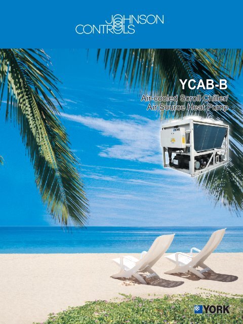
YCAB-B<br />
<strong>Air</strong>-<strong>cooled</strong> <strong>Scroll</strong> <strong>Chiller</strong>/<br />
<strong>Air</strong> Source Heat Pump
<strong>Air</strong>-<strong>cooled</strong> <strong>Scroll</strong> <strong>Chiller</strong>/<strong>Air</strong> Source Heat Pump YCAB-B Series<br />
YORK <strong>Air</strong>-<strong>cooled</strong> <strong>Scroll</strong> <strong>Chiller</strong> / <strong>Air</strong> Source Heat Pump YCAB-B Series provides chilled and hot water for central air<br />
conditioning applications using central station air handling or terminal units. They are completely self-sufficient and are<br />
designed for outdoor (roof or ground level) installation. Each unit includes hermetic flexible scroll compressors, air<strong>cooled</strong><br />
condenser, evaporator, and a microprocessor control center. All components are mounted on a steel base.<br />
Compressor<br />
This unit uses flexible scroll compressors. A system uses<br />
2 to 3 parallel compressors, providing multilevel capacity.<br />
They compressor motor is <strong>cooled</strong> by the refrigerant gas.<br />
A PTC temperature sensor is mounted on the coils at each<br />
phase, providing thermal protection for the motor coils by<br />
sending a thermal signal to the protection module on the<br />
solid-state motor. Across the line starter is used for<br />
compressor motor starting.<br />
Evaporator<br />
Evaporator of YCAB100/130/150/160 is plate type. It is<br />
manufactured, tested and accepted in accordance to JB/8701-<br />
1998 plate heat exchange guidelines. The design pressure is<br />
2.8MPa on refrigerant side and 1.0MPa on water side. Cooler<br />
is wrapped in 19mm thick flexible closed-cell foam.<br />
Evaporator of YCAB200/210/250/270/330 is a directexpansion<br />
shell and tube unit. It is manufactured, tested and<br />
accepted in accordance to GB151-1999 Shell and Tube Heat<br />
Exchanger guidelines, referring to JB6917-1998 Pressure<br />
Container for Refrigerating Equipment. The design pressure<br />
is 2.8MPa on the refrigerant side and 1.0MPa on the water<br />
side. The refrigerant is on the tube side and the chilled water<br />
is on the shell side, where a baffle is provided. The heat<br />
exchanging tube is composed of high efficiency external<br />
threading and seamless copper tubing, and is wrapped in<br />
19mm thick flexible closed-cell foam.<br />
The refrigerant circuits are protected by 350Psig safety valves<br />
for chiller unit and 400Psig safety valves for heat pump unit.<br />
Condenser<br />
Coils - “V” type coils are designed for YCAB 100/130/150/160,<br />
and “W” type for YCAB 200/210/250/270/330. The copper tubes<br />
are mechanically expanded into high-efficiency aluminum fins.<br />
The connecting heat pump unit uses hydrophilic aluminum fins.<br />
Fans - The fans are low-noise and of high-efficinecy. The<br />
blades are made of LY12 aluminum-alloy with a plasticsprayed<br />
surface. Fans are directly driven by independent<br />
motors and positioned for vertical air discharge. All blades<br />
are statically and dynamically balanced.<br />
Motors - The fans are full hermetic, air-<strong>cooled</strong>, three-phase,<br />
squirrel-cage motor, with inner superheat protector and<br />
aluminum case.<br />
Refrigerant Circuit<br />
One or two independent refrigerant circuits will be finished<br />
on each unit. Each circuit includes a main liquid check valve,<br />
filter drier, solenoid valve, sight glass, expansion valve, and<br />
a high/low pressure switch. The refrigeration system is<br />
pressure-tested, leak-tested, and evacuated and charged with<br />
refrigerant. All liquid pipes after the expansion valve and all<br />
suction pipes use flexible closed-cell foam insulation.<br />
General<br />
YORK <strong>Air</strong>-<strong>cooled</strong> <strong>Scroll</strong> <strong>Chiller</strong> / YCAB-B models are assembled completely from the factory. All<br />
related refrigerant circuits and internal wirings are properly connected and the field installation is<br />
easy. It is ready for operation right after connecting water, power and control circuits.<br />
The unit is pressure-tested, evacuated, and fully charged with refrigerant and oil. An operational test<br />
is performed to assure that the refrigeration circuit and control device operate correctly.<br />
The unit structure is made of heavy-gauge, galvanized steel. Each part is pre-processed with zinc<br />
phosphate and coated with polyester powder. The color of the unit surface is gray. There are lifting<br />
holes on the frame for the international container and mounting holes for the damping device.<br />
Nomenclature<br />
YC A B130 S C 50 B<br />
Design Code<br />
50Hz<br />
Refrigerant: C-HCFC-22, B-HFC-407C<br />
Series: S-Cooling only, R-Heat Pump<br />
Nominal Capacity<br />
<strong>Scroll</strong> Compressor<br />
<strong>Air</strong>-<strong>cooled</strong><br />
YORK <strong>Chiller</strong><br />
2
Specifications and Options<br />
Microprocessor Control Center<br />
All controls and starting devices are installed and fully<br />
tested in the factory. The control cabinet includes a power<br />
supply, control center and control devices. All are located<br />
in an enclosure. The cabinet is composed of two<br />
independent parts; a motor starter and a unit controller.<br />
The cabinet has a hinged door. The design of the<br />
enclosure complies with the IP55 waterproof and dustproof<br />
standards. The surface is painted ivory.<br />
The unit is equipped with the following control<br />
functions:<br />
LCD Display<br />
4-row by 15-column English display<br />
Operation Status Display<br />
Operating data - Includes inlet and outlet temperature of<br />
chilled water, ambient temperature, and exhaust and<br />
suction pressures of each system.<br />
Operating fault - When a fault occurs, the unit can self<br />
diagnose, display the cause, and send an alarm to the<br />
buzzer and indicator LED. The failure alarm history is<br />
logged for query.<br />
DI and DO status - Displays the DI (Data Input) and DO<br />
(Data Output) status of all modules.<br />
Control Protection<br />
The unit has the following control protection functions:<br />
Flow switch<br />
External interlock<br />
Frequent compressor start-stop protection<br />
Compressor even running<br />
Compressor overload protection<br />
Fans overload protection<br />
Exhaust overpressure protection<br />
Suction overpressure protection<br />
Low/high water temperature protection<br />
Power protection<br />
The unit also has other control functions such as:<br />
Auto/manual frost protection<br />
Remote monitor and control<br />
Schedule start/stop<br />
Energy control<br />
Manual test function<br />
Operation limit<br />
Plug-and-play system<br />
Network control<br />
RS-485/RS-232 standard serial communication ports<br />
Operation Limitations<br />
Power<br />
Standard power supply is 380V 3N ~ 50Hz. Minimum<br />
allowed voltage is 342V and maximum allowed is 418V.<br />
Operating ambient temperature<br />
The temperature ranges is:<br />
<strong>Chiller</strong> unit: -10 ~ 45<br />
Heatpump unit: -10 ~ 24<br />
Water temperature<br />
The unit can choose the inlet and outlet chilled water<br />
temperature control mode.<br />
Outlet cool water: min. 5 , max. 12<br />
Inlet cool water: min. 7 , max. 17<br />
Outlet hot water: min. 40 , max. 50<br />
Inlet hot water: min. 35 , max. 45<br />
Options<br />
The unit provides the following options:<br />
<strong>Air</strong>-<strong>cooled</strong> Coil Protection<br />
The standard unit uses copper tubes with aluminum fins.<br />
For coastal, fog environment and other corrosive<br />
applications, this unit provides the option to protect the<br />
coils:<br />
<strong>Air</strong>-<strong>cooled</strong> coils with black fins - the aluminum fins are<br />
coated with black epoxy resin.<br />
Unit Protection Grid<br />
A wire-mesh protection grid can be installed around the<br />
unit to protect internal components, preventing<br />
unauthorized operation and keeping ventilation.<br />
High Static Pressure Fans<br />
The unit is capable of choosing a high static pressure fan<br />
(100Pa static pressure), used for applications that need<br />
duct connection.<br />
Evaporator Insulation<br />
The standard unit uses 19mm heat insulation material.<br />
38mm insulation can be chosen if required.<br />
Compressor Noise Reduction Cabinet<br />
A noise reduction cabinet can be installed outside the<br />
compressor. The cabinet is made of porous acoustic<br />
panels and can reduce the operating noise effectively.<br />
Spring Isolator<br />
Level adjustable type spring isolator (field mounted).<br />
3
Main Technical Parameters<br />
Dimension Table<br />
`ççäáåÖ eÉ~íáåÖ= ===============================`çãéêÉëëçê `çåÇÉåëÉê=c~å ====bî~éçê~íçê aáãÉåëáçå ================tÉáÖÜí<br />
cìää<br />
======= =============fåéìí=ht<br />
jçíçê<br />
t~íÉê t~íÉê t~íÉê<br />
oÉÑêáÖê~åí<br />
jçÇÉä oÉÑêáÖÉê~åí `~é~Åáíó `~é~Åáíó äç~Ç<br />
^áêÑäçï<br />
i t e pÜáééáåÖ léÉê~íáåÖ níóK `ççäáåÖ eÉ~íáåÖ `~é~Åáíó=`çåíêçä<br />
mçïÉê níóK cäçï mêÉëëìêÉ máéÉ tÉáÖÜí tÉáÖÜí ÅÜ~êÖÉ<br />
ht ht ÅìêêÉåí<br />
ht ht B ht ã P LÜ ã P LÜ hé~ `çååÉÅíáçå ãã ãã ãã hÖ hÖ<br />
hÖ<br />
v`^_NMMp` NMO J P VKV=ñ=P J NMMJST TPKU NKN=ñ=P P NRUTS=ñ=P QKV NPKR OJNLO? POTN NMSM OPRU NOTM NOUV PRKN<br />
v`^_NPMp` NPQ J O ON=ñ=O J NMMJRM VUKQ NKN=ñ=P P NRUTS=ñ=P SKQ NQKR OJNLO? POTN NMSM OPRU NPMS NPPN PUKM<br />
v`^_NSMp` NRS J O ORKV=ñ=O J NMMJRM NNTKM NKN=ñ=P P NRUTS=ñ=P TKR NUKO OJNLO? POTN NMSM OPRU NRNS NRQS QMKM<br />
v`^_ONMp` OMT J S NMKO=ñ=S J NMMJUPJSTJRMJPP NRMKS NKN=ñ=S S NRUTS=ñ=S VKV NRKO S? POTN OMPU OPRU OTRU OURS PPKQ=ñ=O<br />
v`^_OTMp` OSU J Q OM=ñ=Q J NMMJTRJRMJOR NVSKQ NKN=ñ=S S NRUTS=ñ=S NOKU NUKO S? POTN OMPU OPRU OUNM OVNM PTKM=ñ=O<br />
v`^_PPMp` e`c`JOO PPM J Q ORKP=ñ=Q J NMMJTRJRMJOR OQM NKR=ñ=S S NTPUM=ñ=S NRKU PNKP S? POTN OMPU OQNU PPRM PQUM QNKM=ñ=O<br />
v`^_NMMo` VU NMO P VKS=ñ=P NMKQ=ñ=P NMMJST TOKV NKN=ñ=P P NRUTS=ñ=P QKT NOKR OJNLO? POTN NMSM OPRU NPUO NQMN PUKR<br />
v`^_NPMo` NOT NPN O OM=ñ=O OM=ñ=O NMMJRM VTKS NKN=ñ=P P NRUTS=ñ=P SKN NPKP OJNLO? POTN NMSM OPRU NQPM NQRP QOKM<br />
v`^_NRMo` NQV NRP O OQKU=ñ=O OPKP=ñ=O NMMJRM NOMKO NKR=ñ=P P NTPUM=ñ=P TKN NSKQ OJNLO? POTN NMSM OPRU NSNM NSQM QQKR<br />
v`^_OMMo` NVS OMP S NM=ñ=S VKU=ñ=S NMMJUPJSTJRMJPP NRM NKN=ñ=S S NRUTS=ñ=S VKQ NTKR S? POTN OMPU OPRU OVNM PMSM PUKM=ñ=O<br />
v`^_ORMo` ORQ OSM Q OM=ñ=Q NVKT=ñ=Q NMMJTRJRMJOR NVSKQ NKN=ñ=S S NRUTS=ñ=S NOKN OMKS S? POTN OMPU OPRU OVOS PMTS QOKM=ñ=O<br />
v`^_NMMp_ NMN J O OMKQ=ñ=N J<br />
NOKP=ñ=N<br />
NMMJSP<br />
NMMJPTG<br />
UPKN NKN=ñ=P P NRUTS=ñ=P QKU NPKN OJNLO POTN NMSM OPRU NOOQ NOQP PMKP<br />
v`^_NPMp_ NOS J O OMKQ=ñ=O J NMMJRM VSKR NKN=ñ=P P NRUTS=ñ=P SKM NOKT OJNLO POTN NMSM OPRU NPMS NPPN PQKO<br />
v`^_NSMp_ ec`JQMT` NRO J O OSKM=ñ=O J NMMJRM NONKO NKN=ñ=P P NRUTS=ñ=P TKP NTKM OJNLO POTN NMSM OPRU NQVM NROM PS<br />
v`^_ONMp_ OMV J Q OMKR=ñ=O J NMMJSVJRMJNVGG NRTKP NKN=ñ=S S NRUTS=ñ=S NMKM NTKU S POTN OMPU OPRU OSSQ OTSQ PNKS=ñ=O<br />
NOKP=ñ=O<br />
v`^_OTMp_ OSP J Q OMKR=ñ=Q J NMMJTRJRMJOR NVPKU NKN=ñ=S S NRUTS=ñ=S NOKS NVKU S POTN OMPU OPRU OUNM OVNM PPKP=ñ=O<br />
v`^_PPMp_ POQ J Q ORKM=ñ=Q J NMMJTRJRMJOR OPUKR NKR=ñ=S S NTPUM=ñ=S NRKR PMKO S POTN OMPU OQNU POVU PQOU PSKV=ñ=O<br />
Note: 1. The standard operating conditions:<br />
Cooling: temperature of inlet/outlet chilled water 12°C/7°C, outdoor temperature 35°C.<br />
Heating: temperature of Inlet/outlet chilled water 40°C/45°C, outdoor temperature 7°C.<br />
2. If heat pump unit with HFC-407C is applied, please contact our local office.<br />
3. *The capacity control can be at 100-63%, or 100-37%.<br />
4 **The capacity control can be at 100-81-50-31%, 100-69-38-19% or 100-81-62-31%.<br />
Water Pressure Drop<br />
70<br />
60<br />
50<br />
40<br />
30<br />
20<br />
10<br />
A: YCAB100SC/100RC/100SB<br />
B: YCAB130SC/130RC/130SB<br />
C: YCAB160SC/150RC/160SB<br />
D: YCAB210SC/270SC/330SC<br />
YCAB210SB/270SB/330SB<br />
YCAB200RC/250RC<br />
4<br />
(Y-axis for water pressure drop and X-axis for water flow)
Dimensions<br />
YCAB100SC, YCAB130SC, YCAB160SC, YCAB100SB, YCAB130SB,<br />
YCAB160SB, YCAB100RC, YCAB130RC, YCAB150RC<br />
YCAB210SC, YCAB270SC, YCAB330SC, YCAB210SB,<br />
YCAB270SB, YCAB330SB, YCAB200RC, YCAB250RC<br />
(See note 4)<br />
Note:<br />
1. To avoid the return flow of the condenser and operating faults, Johnson Controls<br />
recommends the minimum distances as follows:<br />
side face to wall: 1525mm rear face to wall: 2450mm<br />
front face to wall: 2450mm top distance: 15000mm<br />
distances between immediate units: 3600mm<br />
If the above distances cannot be met, the unit performance may be impacted or the unit<br />
may abnormally shut down.<br />
No wall should be higher than the top of unit.<br />
To avoid blocking the ventilation of the unit air, there should not be any obstacles inside the<br />
above distances or under the unit. If the unit needs to operate in winter of snow cases, the<br />
mounting height must be increased to assure that the condenser air flows property.<br />
2. Mounting dampening springs will heighten the unit by 135mm overall.<br />
3. The diagrams are schematics, and are not to scale.<br />
4. YCAB330 unit height is 2418mm, and other model’s height is 2358mm.<br />
5
Cooling Performance<br />
6<br />
`ÜáääÉÇ ^áê=lå=qÉãéK=J=ÅçåÇÉåëÉê=E F<br />
=jçÇÉä ï~íÉê=çìí==================OR ====================PM ===================PR ===================QM ===================QR ==================RM<br />
qÉãéK= `~é~Åáíó=ât fåéìí=éçïÉê=ât `~é~Åáíó=ât fåéìí=éçïÉê=ât `~é~Åáíó=ât fåéìí=éçïÉê=ât `~é~Åáíó=ât fåéìí=éçïÉê=ât `~é~Åáíó=ât fåéìí=éçïÉê=ât `~é~Åáíó=ât fåéìí=éçïÉê=ât<br />
R NMR OT NMM PM VQ PP UU PT UO QN TS QR<br />
S NMV OT NMP PM VU PP VO PT UR QN TV QR<br />
v`^_NMMp`<br />
T NNO OT NMT PM NMO PP VR PT UV QN UO QR<br />
U NNT OT NNN PM NMS PP VV PT VO QN US QR<br />
V NON OT NNR PM NMV PP NMO PT VS QN UV QR<br />
NM NOR OT NNV PM NNP PP NMS PT VV QN VO QR<br />
R NPU PS NPN QN NOQ QR NNR RN NMT RS VV SO<br />
S NQQ PS NPS QN NOV QR NOM RN NNO RS NMP SO<br />
v`^_NPMp`<br />
T NRM PS NQO QN NPQ QR NOR RN NNS RS NMT SO<br />
U NRR PT NQT QN NPV QR NPM RN NON RS NNO SO<br />
V NSN PT NRO QN NQQ QR NPR RN NOS RT NNT SO<br />
NM NSS PT NRU QN NRM QR NQM RN NPN RT NOO SO<br />
R NSM QR NRKP RM NQR RR NPT SM NOV SR NOM TN<br />
S NST QR NRV RM NRN RR NQO SM NPQ SS NOR TN<br />
v`^_NSMp`<br />
T NTP QR NSQ RM NRS RR NQT SM NPV SS NPM TN<br />
U NTV QR NTM RM NSO RR NRP SN NQR SS NPS TN<br />
V NUR QR NTT RM NSU RR NRV SN NRM SS NQO TO<br />
NM NVO QS NUP RN NTQ RR NSR SN NRS SS NQT TO<br />
R ONP RS OMQ SO NVR SU NUO TS NSV UQ NRR VP<br />
S OOO RS ONO SO OMN SU NUU TS NTR UQ NSO VP<br />
v`^_ONMp`<br />
T OPN RS ONV SO OMT SU NVQ TS NUN UQ NSV VP<br />
U OQM RS OOT SO ONR SU OMO TS NUV UQ NTR VP<br />
V OQU RS OPR SO OOP SU ONM TS NVS UQ NUO VP<br />
NM ORS RS OQQ SO OPN SU ONT TS OMP UQ NUV VP<br />
R OTS TM OSO TU OQU UT OPO VU ONR NMV NVV NOM<br />
S OUT TM OTO TV ORU UT OQN VU OOQ NMV OMT NOM<br />
v`^_OTMp`<br />
T OVU TN OUP TV OSU UT ORN VU OPQ NMV ONS NOM<br />
U PMV TN OVQ TV OTU UT OSN VU OQP NMV OOS NOM<br />
V POM TO PMQ UM OUU UU OTM VV ORP NMV OPR NOM<br />
NM PPO TO PNR UM OVU UU OUM VV OSO NNM OQQ NON<br />
R PPV VM POP NMM PMT NMV OVM NOM OTO NPN ORR NQO<br />
S PRO VM PPR NMM PNU NNM PMN NON OUP NPN OSR NQO<br />
v`^_PPMp`<br />
T PSS VM PQU NMM PPM NNM PNO NON OVQ NPO OTS NQP<br />
U PTV VN PSN NMN PQP NNM POQ NON PMS NPO OUT NQP<br />
V PVO VN PTQ NMN PRR NNN PPT NOO PNU NPO OVV NQQ<br />
NM QMR VN PUS NMN PSU NNN PQV NOO PPM NPP PNN NQQ<br />
R NMN OS VS OV VN PO UR PS TV QM TP QQ<br />
S NMR OS VV OV VQ PO UU PS UO QM TS QQ<br />
v`^_NMMo`<br />
T NMU OS NMP OV VU PO VO PS UR QM TV QQ<br />
U NNO OS NMT OV NMN PO VR PS UV QM UO QQ<br />
V NNS OS NNN OV NMR PO VU PS VO QM US QQ<br />
NM NOM OS NNQ OV NMU PO NMO PS VR QM UV QQ<br />
R NPN PR NOQ PV NNT QP NMV QU NMO RQ VQ RV<br />
S NPS PR NOV PV NOO QP NNQ QU NMS RQ VU RV<br />
v`^_NPMo`<br />
T NQO PR NPQ PV NOT QP NNV QU NNM RQ NMO RV<br />
U NQT PR NPV PV NPO QP NOP QV NNR RQ NMS RV<br />
V NRO PR NQQ PV NPT QP NOU QV NNV RQ NNN SM<br />
NM NRT PR NRM PV NQO QP NPP QV NOQ RQ NNR SM<br />
R NRQ QQ NQS QV NPV RQ NPN RV NOP SQ NNR SV<br />
S NRV QQ NRO QV NQQ RQ NPS RV NOU SQ NOM TM<br />
v`^_NRMo`<br />
T NSR QQ NRT QV NQV RQ NQN RV NPP SR NOR TM<br />
U NTN QQ NSP QV NRR RQ NQS RV NPU SR NPM TM<br />
V NTT QR NSV QV NSM RQ NRO SM NQQ SR NPR TM<br />
NM NUP QR NTQ RM NSS RQ NRU SM NQV SR NQN TM<br />
R OMO RR NVP SN NUR ST NTO TR NSM UP NQT VN<br />
S ONM RR OMM SN NVM ST NTU TR NSS UP NRP VN<br />
v`^_OMMo`<br />
T ONV RR OMU SN NVS ST NUQ TR NTO UP NSM VN<br />
U OOT RR ONR SN OMQ ST NVN TR NTV UP NSS VN<br />
V OPQ RR OOP SN ONN ST NVU TR NUR UP NTO VN<br />
NM OQO RR OPN SN ONV ST OMS TR NVO UP NTV VN<br />
R OSO TM OQU TU OPR UT OOM VU OMQ NMV NUU NOM<br />
S OTO TM ORU TV OQR UT OOV VU ONP NMV NVT NOM<br />
v`^_ORMo`<br />
T OUO TN OSU TV ORQ UT OPU VU OON NMV OMR NOM<br />
U OVP TN OTU TV OSQ UT OQT VU OPN NMV ONQ NOM<br />
V PMQ TO OUV UM OTQ UU ORT VV OQM NMV OOP NOM<br />
NM PNQ TO OVV UM OUQ UU OST VV OQV NNM OPN NON
Heating Performance<br />
<br />
<br />
<br />
<br />
<br />
<br />
<br />
<br />
<br />
<br />
<br />
<br />
<br />
<br />
<br />
<br />
<br />
<br />
<br />
<br />
<br />
<br />
<br />
<br />
<br />
<br />
<br />
<br />
<br />
<br />
<br />
The above table is based on the following:<br />
1. Input power (kW) is for compressor and fan.<br />
2. Water flow is the same as the flow under the standard operating condition (refer to the table on page 4).<br />
3. If unit with HFC-407C is applied, please contact our local office.<br />
7
Johnson Controls is the global leader in energy management and<br />
building systems for a comfortable, healthy and safe building environment,<br />
maximizing productivity and energy-efficiency.<br />
We are a single source of integrated heating/cooling, lighting, fire,<br />
security and wireless infrastructure products for buildings and industrial<br />
plants.<br />
Our comprehensive life-cycle approach to in-building technology and<br />
operations includes planning and design, installation and integration,<br />
optimization and maintenance as well as integrated real estate and<br />
facility management services.<br />
We operate from a comprehensive network of more than 100 sales and<br />
support centers across Asia and the Pacific, with more than 8,000<br />
dedicated professionals located in Australia, China, Hong Kong, India,<br />
Indonesia, Japan, Korea, Macau, Malaysia, New Zealand, Philippines,<br />
Singapore, Taiwan, Thailand and Vietnam.<br />
Our Metasys building automation and YORK HVAC brands have market-leading<br />
reputations for quality and innovation.<br />
Johnson Controls is the choice of world-renowned structures and<br />
organisations including the Olympics, the US Capitol, the Kremlin, the<br />
Eiffel Tower, the Sydney Opera House, India's ITC Centre, the Hong Kong<br />
Convention & Exhibition Centre and the world's tallest buildings –<br />
Kuala Lumpur's Petronas Towers, Taipei 101 and the Shanghai World<br />
Finance Centre.<br />
www.johnsoncontrols.com<br />
Asia Headquarters<br />
20/F, Tower 1, 2 & 3, Enterprise Square,<br />
9 Sheung Yuet Road, Kowloon Bay,<br />
Kowloon, Hong Kong<br />
Tel : +852 2590 0012 Fax: +852 2516 5648<br />
Australia<br />
Tel : +61 (2) 9805 8317<br />
Fax: +61 (2) 9889 3016<br />
Korea<br />
Tel : +82 (2) 554 5935<br />
Fax: +82 (2) 554 5739<br />
India<br />
Tel : +91 (22) 3088 1455<br />
Fax: +91 (22) 3088 1534<br />
Malaysia<br />
Tel : +60 (3) 7628 4300<br />
Fax: +60 (3) 7874 1180<br />
Indonesia<br />
Tel : +62 (21) 626 3535<br />
Fax: +62 (21) 659 8875<br />
New Zealand<br />
Tel : +64 (9) 444 6434<br />
Fax: +64 (9) 444 2092<br />
Japan<br />
Tel : +81 (3) 3230 7710<br />
Fax: +81 (3) 3230 7340<br />
Philippines<br />
Tel : +63 (2) 723 0631<br />
Fax: +63 (2) 723 2109<br />
Singapore<br />
Tel : +65 6284 5722<br />
Fax: +65 6283 3015<br />
Thailand<br />
Tel : +66 (2) 717 0751<br />
Fax: +66 (2) 717 0750<br />
Vietnam<br />
Tel : +84 (8) 526 1205<br />
Fax: +84 (8) 526 1206<br />
Hong Kong<br />
Tel : +852 2590 0012<br />
Fax: +852 2516 5648<br />
China (Shanghai)<br />
Tel : +86 (21) 6276 6509<br />
Fax: +86 (21) 6277 3543<br />
Taiwan<br />
Tel : +886 (2) 2657 5568<br />
Fax: +886 (2) 2657 6388<br />
Macau<br />
Tel : +853 2875 1820<br />
Fax: +853 2875 1821<br />
© 2007 Johnson Controls, Inc.<br />
ASIAPUBL-12005.E(0207)


