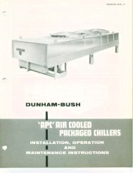
Screw Type Air-Cooled Packaged Chillers ACWC-SC
Screw Type Air-Cooled Packaged Chillers ACWC-SC
Screw Type Air-Cooled Packaged Chillers ACWC-SC

You also want an ePaper? Increase the reach of your titles
YUMPU automatically turns print PDFs into web optimized ePapers that Google loves.
KEY TO WIRING DIAGRAM INDEXING SYSTEM<br />
The wiring diagrams and sequence instructions on the following pages have been devised to simplify the understanding and tracing of circuit<br />
theory. The following key shows how the indexing system can be used.<br />
12 Line number on wiring diagram<br />
[12] Line number in text<br />
(RS) Component identification symbol in text (Relay #5)<br />
~ Normally open contact- line number location<br />
~ Normally closed contact- line number location<br />
& Note number<br />
@ Holding coil -<br />
line number location<br />
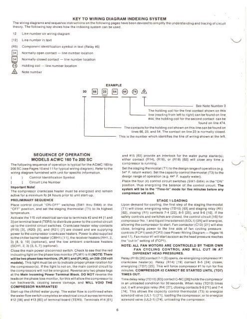
EXAMPLE<br />
30<br />
~ §] §]<br />
@@&<br />
~<br />
See Note Number 3<br />
The holding coil for the first contact shown on this<br />
line (reading from left to right) can be found on line<br />
#44; the holding coil for the second contact can be<br />
found on line #74.<br />
The contacts for the holding coil shown on this line can be found on<br />
lines 66, 23, and 54. The contact on line 23 is normally closed.<br />
This is the number which identifies the line of wiring shown at the left.<br />
SEQUENCE OF OPERATION<br />
MODELS <strong>ACWC</strong> 160 To 200 <strong>SC</strong><br />
The following sequence of operation is typical for the <strong>ACWC</strong> 160 to<br />
200 <strong>SC</strong> (see Pages 10 and 11 for typical wiring diagram). Refer to the<br />
wiring diagram furnished with unit for specific information.<br />
Control Identification Symbol<br />
Circuit Line Number<br />
Important Notel<br />
The compressor crankcase heater must be energized and remain<br />
active for a minimum fa 24 hours prior to unit start-up.<br />
PRELIMINARY SEQUENCE<br />
Place control circuit "ON-OFF" switches (SW1 thru SW4) in the<br />
"OFF" position, and set the staging thermostat (T1) to its highest<br />
temperature.<br />
Activate the 115 volt electrical service to terminals #2 and #4 [1 and<br />
3] on terminal board (TEAS) to distribute power to the control circuit<br />
up to the control circuit switches. Crankcase heater relay contacts<br />
(R19) (3]. (R20) [5]. and (R21) [7] are closed and are supplying<br />
power to the compressor crankcase heaters. Power is also supplied<br />
to the chiller barrel heater (CBH1) (11]. the receiver heaters (RH1, 2,<br />
3) (8, 9, 1 0] (optional), and the low ambient crankcase heaters<br />
(<strong>SC</strong>H1, 2, 3) [3, 5, 7] (optional).<br />
Close the main power disconnect switch. Check to see that the red<br />
indicating light on the phase loss monitor (PLM1) is lit (NOTE: There<br />
will be two phase loss monitors, (PLM1) and (PLM2), on 208-230 volt<br />
models). This light must be on to indicate proper phase rotation for<br />
the compressor(s). If the light is not on, the main control circuit to<br />
the compressors will not be energized. Reverse any two phase legs<br />
at the Main Incoming Power Terminal Block. DO NOT reverse the<br />
leads on the phase loss monitor, for this will allow the compressor to<br />
run backwards, causing severe damage, and WILL VOID THE<br />
COMPRESSOR WARRANTEE!<br />
Start-up the chilled water pump. The water flow is confirmed when<br />
the water flow switch completes an electrical circuit across terminals<br />
#12 (58] and #13 [60] of terminal board (TEAS). Terminals #14 [61]<br />
and #15 [63] provide an interlock for the water pump starter(s);<br />
either contact (R14). (R16), or (R18) [62] will close any time a<br />
compressor is running.<br />
Set the staging thermostat (T1) to the design range of operation (e.g.<br />
54° F. return water) . Set the capacity control thermostat (T3) to the<br />
design range of operation (e.g. 44° F. supply water).<br />
Place the four (4) control circuit switches (SW1-SW4) in the "ON"<br />
position, thus energizing the balance of the control circuit. The<br />
system will be In the "Time-In" mode for five minutes before any<br />
compressor will start.<br />
STAGE 1 LOADING<br />
Upon demand for cooling, the first step of the staging thermostat<br />
(T1) will close, energizing relay (TD10) (63] and staging relay (R1)<br />
[62]. closing (R1) contacts 7-4 [22]. 8-5 [25]. and 9-6 (16] . If the<br />
safety controls and switches are closed, the control circuit [16] for<br />
compressor No.1 and liquid line solenoid (SOL 1) (25] will energize,<br />
allowing the compressor to start. Fan contactor (C13) (21] will also<br />
close, bringing power to the line side of fan cycling pressure<br />
controls (FCP1) and (FCP2) (see Power Wiring Diagram- Pages 16<br />
and 17). Fan motor #1 will start as soon as the head pressure reaches<br />
the "cut-in" setting of (FCP1 ).<br />
NOTE: ALL FAN MOTORS ARE CONTROLELD BY THEIR OWN<br />
FAN CYCLING CONTROL AND WILL CUT IN AT<br />
DIFFERENT HEAD PRESSURES.<br />
Relay (R19) [20] contact 7-1 [3] opens, de-energizing compressor#1<br />
crankcase heater(s). Relay (R14) (19] contact 8-5 (24] closes,<br />
energizing (TD7) [23]. This will force compressor #1 to run for five<br />
minutes. COMPRESSOR #2 CANNOT BE STARTED UNTIL (TD7)<br />
TIMES OUT.<br />
Time delay relay (TD1 0) [63] contact C-NC (26] holds the compressor<br />
in an unloaded condition for 30 seconds. When relay (TD10) times<br />
out, it will energize relay (R4) [27]. closing contacts 9-6 [71] and 7-4<br />
[74] . This allows the capacity control thermostat (T3) to energize<br />
solenoid valve (UL 1-1) [71]. loading the compressor; or to energize<br />
solenoid valve (UL2-1) [74]. unloading the compressor.<br />
\....__./<br />
, -~<br />
6