Screw Type Air-Cooled Packaged Chillers ACWC-SC
Screw Type Air-Cooled Packaged Chillers ACWC-SC
Screw Type Air-Cooled Packaged Chillers ACWC-SC

You also want an ePaper? Increase the reach of your titles
YUMPU automatically turns print PDFs into web optimized ePapers that Google loves.
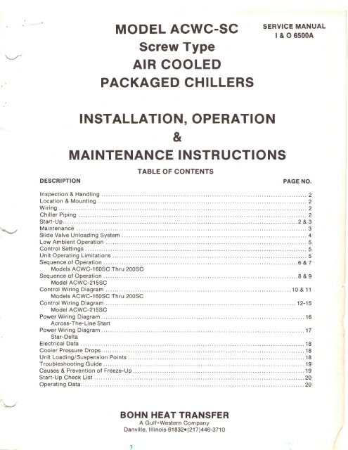
MODEL <strong>ACWC</strong>-<strong>SC</strong><br />
<strong>Screw</strong> <strong>Type</strong><br />
AIR COOLED<br />
PACKAGED CHILLERS<br />
SERVICE MANUAL<br />
I & 0 6500A<br />
DE<strong>SC</strong>RIPTION<br />
INSTALLATION, OPERATION<br />
&<br />
MAINTENANCE INSTRUCTIONS<br />
TABLE OF CONTENTS<br />
PAGE NO.<br />
Inspection & Handling ........................................................................................... 2<br />
Location & Mounting ........ ... ...... .................................................................. ...... .... 2<br />
Wiring .............................................................................................................. 2<br />
Chiller Piping ..................................................................................................... 2<br />
Start-Up ........................................................................................................ 2 & 3<br />
Maintenance .... ..... ........ ..... ........... ......... .............. ... .... .... ........ .. ......................... 3<br />
Slide Valve Unloading System .................................................................................. 4<br />
Low Ambient Operation ......................................................................................... 5<br />
Control Settings .................................................................................................. 5<br />
Unit Operating Limitations ...................................................................................... 5<br />
Sequence of Operation ...................................................................................... 6 & 7<br />
Models <strong>ACWC</strong>-160<strong>SC</strong> Thru 200<strong>SC</strong><br />
Sequence of Operation ...................................................................................... 8 & 9<br />
Model <strong>ACWC</strong>-215<strong>SC</strong><br />
Control Wiring Diagram .................................................................................. 10 & 11<br />
Models <strong>ACWC</strong>-160<strong>SC</strong> Thru 200<strong>SC</strong><br />
Control Wiring Diagram .................................................................................... 12-15<br />
Model <strong>ACWC</strong>-215<strong>SC</strong><br />
Power Wiring Diagram ............. .... . ... ... . .... .... .. ..... . ... .. .... .. ....... ...................... ......... 16<br />
Across-The-Line Start<br />
Power Wiring Diagram .......................................................................................... 17<br />
Star-Delta<br />
Electrical Data ................................................................................................... 18<br />
Cooler Pressure Drops .......................................................................................... 18<br />
Unit Loading/Suspension Points .............................................................................. 18<br />
Troubleshooting Guide .... .. ........... .... ........... ... .......... ............ ..... ..... .. .... ... ............ . 19<br />
Causes & Prevention of Freeze-Up ............................................................................ 19<br />
Start-Up Check List ...................................... ..... .. .. ... ........................................... 20<br />
Operating Data ... ..... ........... .... . ... .... ..... .. ................ ....... ........................... ... ...... .. 20<br />
BOHN HEAT TRANSFER<br />
A Gulf+Western Company<br />
Danville, Illinois 61832•{217)446-371 0<br />
..<br />
!<br />
I
INSPECTION & HANDLING<br />
When unit is received, it should be checked for visible or concealed<br />
damage. If damage has occurred it should be reported to the carrier<br />
imme diately .o.nd clo.im filed .<br />
Models <strong>ACWC</strong> 160<strong>SC</strong> thru 215<strong>SC</strong> are factory mounted on two (2)<br />
permanent angle beam, carbon steel skids. Eight (8) 2W' lifting eyes<br />
are provided in the skids to allow rigging. Spreader bars must be<br />
used between rigging lines to prevent damage to the unit. Rollers<br />
may be used under the skids to facilitate moving the unit a short<br />
distance. Physical damage to the unit, after acceptance, Is not the<br />
responsibility of the factory.<br />
LOCATION & MOUNTING<br />
Model <strong>ACWC</strong> <strong>Air</strong> <strong>Cooled</strong> <strong>Packaged</strong> Water <strong>Chillers</strong> are designed for<br />
outdoor application and may be mounted on roof or at ground level.<br />
<strong>Air</strong> flow through the condenser is vertical and the unit may be<br />
located adjacent to outside of building or on roof without regard for<br />
prevailing wind direction.<br />
Since these units are air cooled, the flow of air to and from the<br />
condenser coil must not be impeded. There must be no obstruction<br />
above the unit that would tend to deflect discharge air downward<br />
where it could be recirculated back to the inlet of the unit. The<br />
required overhead air space should be a minimum of eight (8) feet.<br />
Ductwork must not be applied to the fan outlets.<br />
The unit must be installed with sufficient clearance for air entrance<br />
to the condenser coil and for servicing access. The unit should be<br />
located no closer than four (4) feet from any wall or other obstruction.<br />
Clearance must be provided at either end of the unit to permit<br />
removal of tubes from the chiller.<br />
Unit must be set on a solid and level foundation.<br />
On roof installations the unit should be mounted on support beams<br />
which span load-bearing walls to prevent excessive vibration.<br />
On ground level installations, the unit should be mounted on a<br />
substantial base that will not settle. A one-piece concrete slab with<br />
footings extended below the frost line is recommended. A space<br />
should be left between the slab and the building to prevent the<br />
transmission of sound and vibration.<br />
CHILLER PIPING<br />
The chiller inlet (return) water pipe should be connected to the water<br />
connection closest to the control panel end of the unit and the outlet<br />
(:.upply) vvdte• 1-'ifJt::
. CAUTION:<br />
The discharge line valve must be open before starting the compressor.<br />
Liquid line valves must also be open for sustained operation.<br />
All compressors are soli a mountea on 1sopads, therefore, compressor<br />
hold-down bolts must not be loosened. Loosening these bolts will<br />
cause excessive vibration of the compressor and may result in<br />
refrigerant line breakage. Prior to start-up check all compressor<br />
hold-down bolts for tightness.<br />
MAINTENANCE<br />
CONDENSER<br />
Units equipped with belt drive fans have inherently protected<br />
motors. Fan belts, fan bearings and motor bearings require periodic<br />
maintenance as follows:<br />
1. Fan Belts -After two (2) weeks operation, the belts will have<br />
nearly reached their permanent stretch, therefore, each belt<br />
should be checked again and proper adjustments made. To<br />
maintain good fan and motor operation, the belt tension should be<br />
checked at three (3) month intervals.<br />
2. Fan Bearings- Each fan shaft is provided with ball bearings of<br />
the relubricatable type. Each bearing is provided with grease<br />
fittings, accessible through the individual motor access panels. It<br />
is recommended the bearings be greased by adding 4 to 5 shots<br />
with a hand gun. The suggested greasing interval is indicated on a<br />
sticker attached to the unit.<br />
3. Motor Bearings- Each motor is equipped with ball bearings. Ball<br />
bearings consume a very small amount of lubricant, but enough<br />
must be present at all time to prevent motor injury. The length of<br />
time a bearing can run without having grease added or replaced<br />
will depend upon the operating conditions. Under normal<br />
operating conditions, the motor bearings should be lubricated at<br />
2000 hour operating intervals. The lubricant should be from a<br />
clean closed container and should be an anti-friction type bearing<br />
grease-free from solid fillers or other harmful ingredients.<br />
Lubricant should have a safe operating temperature of 2000° F.<br />
The air inlet of the condenser coil should be kept clean through a<br />
regular preventative maintenance program.<br />
Locate the discharge pressure port adjacent to solenoid valve<br />
UL-3 (see drawing below); remove the cap and release the<br />
residual pressure by pushing in on the pressure port fitting itself.<br />
Pump oil into this flU' t u11til u,., uil level Is to the tOP Of the sight<br />
glass.<br />
Replace the discharge port cap. Re-open the discharge line valve.<br />
Do not allow compressor to run with discharge valve closed.<br />
Place the system "ON-OFF" switch in the "ON" position. Using a<br />
jumper wire, make a "short" for five (5) seconds between terminal<br />
#4 on terminal block TER5 and the switched terminal of a solenoid<br />
valve feeding the circuit you have just "blown" (e .g. terminal #121<br />
on TER4 to energize SOL 1 ). Reset return water thermostat (~1) to<br />
the operational temperature setting and allow unit to return to<br />
normal operation.<br />
2. RECOMMENDED OIL- The unit is factory-charged with BOHN<br />
SR-30 refrigeration oil.<br />
Do not add any other type of oil to this factory charge.<br />
Do not operate compressor If oil level is below one-half ('h) sight<br />
glass.<br />
If the oil level is below the minimum specified above, and BOHN<br />
SR-30 is not on hand, you may drain the entire factory oil charge,<br />
then refill with SUN ISO 4GS refrigeration oil. The factory (BOHN)<br />
oil is of the synthetic type and will not mix with SUN ISO 4GS. Do<br />
not attempt to operate the screw compressor with any oil other<br />
than these two specified above.<br />
It is suggested that a gallon or more of BOHN SR-30 oil be<br />
obtained and kept on hand at the job site. The substitution of<br />
SUNISO 4GS oil, as outlined above, will result in a 2% to 4%<br />
capacity loss, and no reduction in input K.W.<br />
3. COMPRESSOR REPAIRS (Internal) - Contact factory or an<br />
authorized BOHN Service Agency if a compressor malfunction is<br />
suspected.<br />
4. COMPRESSOR REPAIRS (External) - Proper operation of<br />
unloaded start, loading, and unloading is controlled by solenoid<br />
valves UL-1 , UL-2 and UL-3. Any of these three (3) solenoid valves<br />
may be repaired or replaced in the field, as required.<br />
HIGH PRESSURE<br />
PORT<br />
COMPRESSOR<br />
1. OIL LEVEL - The oil level in the compressor(s) should be<br />
checked periodically, with the compressor either running or<br />
stopped. If the oil level is below one-half ( '12 ) the sight glass, oil<br />
must be added.<br />
Oil should be added only with the compressor shut off. To do so,<br />
turn the return water thermostat (T1) to a higher temperature<br />
setting, and wait for the unit to pumpdown and shutoff. Place the<br />
system "ON-OFF" switch in the "OFF" position. Close the line<br />
valve in the discharge line between compressor and condenser.<br />
Refrigerant pressure inside of the compressor will now be<br />
approximately 80 to 90 PSI G. The low pressure cut-out setting is<br />
35 PSIG, but the residual discharge pressure (upstream of the<br />
discharge check valve) will equalize back into the suction side<br />
after the compressor stops.<br />
3
SLIDE VALVE<br />
UNLOADING SYSTEM<br />
1 ne tlonn screw compressor capacity control system for infinite<br />
modulation consists of a slide valve and hydraulic piston/ cylinder<br />
operator internal to the compressor; plus three hydraulic solenoid<br />
valves (UL-1, UL-2 & UL-3) piped externally.<br />
The slide valve forms a portion of the chamber wall in which the<br />
rotors turn; thus, its position with respect to the rotors determines<br />
the effective rotor length and thereby the percent of full load<br />
capacity.<br />
Upon compressor start-up, UL-3 is opened. This allows oil pressure<br />
to act upon the hydraulic piston, holding it in the fully unloaded<br />
position. After 30 seconds, during which time full oil flow is<br />
established to all bearings surfaces, UL-3 is closed. At this point, the<br />
temperature controller is free to open and close UL-1 or UL-2 in<br />
response to the supply water temperature.<br />
The slide valve will move to the left (loading) by force of discharge<br />
pressure, whenever UL-1 opens to permit flow to the oil return (low<br />
pressure) line. The slide valve will move to the right (unloading)<br />
whenever UL-2 opens the oil supply (high pressure) line, since the<br />
force of the oil exceeds that of the discharge gas.<br />
The temperature controller sends a series of power (energizing)<br />
" pulses" to the appropriate solenoid to adjust to load conditions.<br />
The further the supply water temperature is from the controller set<br />
point, the longer is the duration of the pulses. The series of pulses<br />
will continue until the controller is satisfied. As the water temperature<br />
approaches the set point, the pulses become quite brief to prevent<br />
overshooting the set point.<br />
This method of compressor unloading in conjunction with supply<br />
water sensing minimizes action/ reaction lag time and overshoot<br />
resulting in an exceptionally precise and stable control of supply<br />
water temperature.<br />
r<br />
Hydraulic Piston<br />
Load<br />
¢::J<br />
Unload<br />
c::><br />
Oil Pressure<br />
Vent to<br />
Slide Valve<br />
Suction<br />
~<br />
Oil Pressure Lines<br />
<strong>Screw</strong> Rotor<br />
UL-1<br />
Oil<br />
Return<br />
Oil<br />
Supply<br />
The following table lists solenoid valve position for all three<br />
operating modes.<br />
UL-1 UL-2 UL-3<br />
Starting Close Close Open<br />
Loading Open Close Close<br />
Unloading Close Open Close<br />
'-...../'<br />
4
Due to the wide range of applications, it is sometimes necessary to<br />
operate the <strong>Air</strong> <strong>Cooled</strong> <strong>Packaged</strong> Water <strong>Chillers</strong> at ambients below<br />
summer conditions. Without proper control, when ambients drop<br />
below 60° F. the pressure differential between the condenser and<br />
the evaporator is below the level to insure proper thermal expansion<br />
valve operation. As a result, the unit may cycle on low pressure<br />
control with the possibility of evaporator freezing. Three types of<br />
system control are available allowing the units to operate at the<br />
ambients indicated:<br />
FAN CYCLING<br />
MEDIUM AMBIENT CONTROL TO 30° F.<br />
(STANDARD EQUIPMENT -FACTORY INSTALLED)<br />
A fan cycling control is standard on all <strong>Air</strong> <strong>Cooled</strong> <strong>Packaged</strong> Water<br />
<strong>Chillers</strong> to prov1de proper operating head pressures, in ambient<br />
conditions to 30° F.<br />
This is an automatic operation in which the condenser fans are<br />
cycled on and off, as required, in response to head pressure. With<br />
two compressors running, three fans are cycled (in sequence) on<br />
five-fan units; four fans on six-fan units; and five fans on seven-fan<br />
units. With one compressor running, all but the lead fan are cycled in<br />
sequence, in response to head pressure.<br />
LOW AMBIENT OPERATION<br />
This arrangement provides positive start-up control down to +30° F.<br />
by delaying the condenser fan operation until a predetermined head<br />
pressure is obtained.<br />
GRAVITY (Discharge) DAMPERS<br />
LOW AMBIENT CONTROL TO oo F.<br />
(OPTIONAL EQUIPMENT- FACTORY INSTALLED)<br />
All condenser fans are equipped with gravity dampers mounted on<br />
the fan discharge to minimize the effect of prevailing winds; and to<br />
prevent convection drafts up through the condenser coil in still air.<br />
All compressors are enclosed in individual insulated housings. An<br />
auxiliary heater is included to supplement the standard crankcase<br />
heater; the temperature within the compressor compartment is<br />
thermostatically controlled.<br />
The standard condenser fan cycling package, operating in conjunction<br />
with the discharge dampers, will maintain suitable head<br />
pressure down to oo F. ambient. A 90-second time delay relay<br />
provides an electrical by pass around the low pressure freezestat to<br />
prevent nuisance tnp-out during cold start-up.<br />
<strong>ACWC</strong>-<strong>SC</strong><br />
CONTROL SETTINGS<br />
PRESSURE ACTUATED LEGEND FACTORY SETTING<br />
High Pressure Control HP-1 Cut-In 300 PISG<br />
(Manual Reset) HP2 & HP3 Cut-Out 365 PSIG<br />
Pumpdown Control PD1 Cut-In 55 PSIG<br />
(Auto Reset) PD2 & PD3 Cut-Out 35 PSIG<br />
Fan Cycling Pressure Control 2 Fan Cell Cut-In (PSIG) Cut-Out<br />
(Adjustable) FCP 1 280 170<br />
FCP 2 295 180<br />
3 Fan Cell<br />
FCP 1 260 160<br />
FCP 2 275 175<br />
FCP 3 290 215<br />
4 Fan Cell<br />
FCP 1 260 160<br />
FCP 2 275 175<br />
FCP3 285 210<br />
FCP4 295 235<br />
Low Pressure Freeze Control LPF 1 Cut-Out 54 PSIG<br />
(Manual Reset) LPF 2 & LPF-3<br />
--<br />
TEMPERATURE ACTUATED LEGEND FACTORY SETTING<br />
Chiller Low Water Temperature Thermostat T2 Cut-Out 37° F.<br />
Chiller Water Cycling Thermostat (Adjustable) T1 Dial Set At 55° F.<br />
Chiller Heater Thermostat Included With Cut- In 40° F.<br />
(Non-Adjustable CBH1 Heater Cut-Out 45° F.<br />
Oil Temperature Safety Control OTS 1<br />
(Adjustable) OTS 2 Cut-Out 240° F.<br />
Manual Reset<br />
OTS3<br />
Capacity Control Thermostat (Adj.) Mode Control Position T3 Dial Set At 44° F.<br />
-(."'-._./<br />
UNIT OPERATING LIMITATIONS<br />
1. Maximum ambient air to condenser is 115° F. (60 Hertz operation).<br />
2. Maximum allowable cooler water pressure is 150 PSI G.<br />
3. Maximum allowable water temperature to cooler is 75° F.<br />
4. Units must not have leaving water temperatures of 42° F. or lower unless used with a glycol solution.<br />
5. Unit must be allowed to pumpdown at the end of each operating cycle (except on safety control shutdown).<br />
5
KEY TO WIRING DIAGRAM INDEXING SYSTEM<br />
The wiring diagrams and sequence instructions on the following pages have been devised to simplify the understanding and tracing of circuit<br />
theory. The following key shows how the indexing system can be used.<br />
12 Line number on wiring diagram<br />
[12] Line number in text<br />
(RS) Component identification symbol in text (Relay #5)<br />
~ Normally open contact- line number location<br />
~ Normally closed contact- line number location<br />
& Note number<br />
@ Holding coil -<br />
line number location<br />
EXAMPLE<br />
30<br />
~ §] §]<br />
@@&<br />
~<br />
See Note Number 3<br />
The holding coil for the first contact shown on this<br />
line (reading from left to right) can be found on line<br />
#44; the holding coil for the second contact can be<br />
found on line #74.<br />
The contacts for the holding coil shown on this line can be found on<br />
lines 66, 23, and 54. The contact on line 23 is normally closed.<br />
This is the number which identifies the line of wiring shown at the left.<br />
SEQUENCE OF OPERATION<br />
MODELS <strong>ACWC</strong> 160 To 200 <strong>SC</strong><br />
The following sequence of operation is typical for the <strong>ACWC</strong> 160 to<br />
200 <strong>SC</strong> (see Pages 10 and 11 for typical wiring diagram). Refer to the<br />
wiring diagram furnished with unit for specific information.<br />
Control Identification Symbol<br />
Circuit Line Number<br />
Important Notel<br />
The compressor crankcase heater must be energized and remain<br />
active for a minimum fa 24 hours prior to unit start-up.<br />
PRELIMINARY SEQUENCE<br />
Place control circuit "ON-OFF" switches (SW1 thru SW4) in the<br />
"OFF" position, and set the staging thermostat (T1) to its highest<br />
temperature.<br />
Activate the 115 volt electrical service to terminals #2 and #4 [1 and<br />
3] on terminal board (TEAS) to distribute power to the control circuit<br />
up to the control circuit switches. Crankcase heater relay contacts<br />
(R19) (3]. (R20) [5]. and (R21) [7] are closed and are supplying<br />
power to the compressor crankcase heaters. Power is also supplied<br />
to the chiller barrel heater (CBH1) (11]. the receiver heaters (RH1, 2,<br />
3) (8, 9, 1 0] (optional), and the low ambient crankcase heaters<br />
(<strong>SC</strong>H1, 2, 3) [3, 5, 7] (optional).<br />
Close the main power disconnect switch. Check to see that the red<br />
indicating light on the phase loss monitor (PLM1) is lit (NOTE: There<br />
will be two phase loss monitors, (PLM1) and (PLM2), on 208-230 volt<br />
models). This light must be on to indicate proper phase rotation for<br />
the compressor(s). If the light is not on, the main control circuit to<br />
the compressors will not be energized. Reverse any two phase legs<br />
at the Main Incoming Power Terminal Block. DO NOT reverse the<br />
leads on the phase loss monitor, for this will allow the compressor to<br />
run backwards, causing severe damage, and WILL VOID THE<br />
COMPRESSOR WARRANTEE!<br />
Start-up the chilled water pump. The water flow is confirmed when<br />
the water flow switch completes an electrical circuit across terminals<br />
#12 (58] and #13 [60] of terminal board (TEAS). Terminals #14 [61]<br />
and #15 [63] provide an interlock for the water pump starter(s);<br />
either contact (R14). (R16), or (R18) [62] will close any time a<br />
compressor is running.<br />
Set the staging thermostat (T1) to the design range of operation (e.g.<br />
54° F. return water) . Set the capacity control thermostat (T3) to the<br />
design range of operation (e.g. 44° F. supply water).<br />
Place the four (4) control circuit switches (SW1-SW4) in the "ON"<br />
position, thus energizing the balance of the control circuit. The<br />
system will be In the "Time-In" mode for five minutes before any<br />
compressor will start.<br />
STAGE 1 LOADING<br />
Upon demand for cooling, the first step of the staging thermostat<br />
(T1) will close, energizing relay (TD10) (63] and staging relay (R1)<br />
[62]. closing (R1) contacts 7-4 [22]. 8-5 [25]. and 9-6 (16] . If the<br />
safety controls and switches are closed, the control circuit [16] for<br />
compressor No.1 and liquid line solenoid (SOL 1) (25] will energize,<br />
allowing the compressor to start. Fan contactor (C13) (21] will also<br />
close, bringing power to the line side of fan cycling pressure<br />
controls (FCP1) and (FCP2) (see Power Wiring Diagram- Pages 16<br />
and 17). Fan motor #1 will start as soon as the head pressure reaches<br />
the "cut-in" setting of (FCP1 ).<br />
NOTE: ALL FAN MOTORS ARE CONTROLELD BY THEIR OWN<br />
FAN CYCLING CONTROL AND WILL CUT IN AT<br />
DIFFERENT HEAD PRESSURES.<br />
Relay (R19) [20] contact 7-1 [3] opens, de-energizing compressor#1<br />
crankcase heater(s). Relay (R14) (19] contact 8-5 (24] closes,<br />
energizing (TD7) [23]. This will force compressor #1 to run for five<br />
minutes. COMPRESSOR #2 CANNOT BE STARTED UNTIL (TD7)<br />
TIMES OUT.<br />
Time delay relay (TD1 0) [63] contact C-NC (26] holds the compressor<br />
in an unloaded condition for 30 seconds. When relay (TD10) times<br />
out, it will energize relay (R4) [27]. closing contacts 9-6 [71] and 7-4<br />
[74] . This allows the capacity control thermostat (T3) to energize<br />
solenoid valve (UL 1-1) [71]. loading the compressor; or to energize<br />
solenoid valve (UL2-1) [74]. unloading the compressor.<br />
\....__./<br />
, -~<br />
6
Relay (R14) (19] contact 7-4 [62] closes, which completes the<br />
interlock circuit for the water circulating pump.<br />
~TAGE! Z LOADINu<br />
Upon a further increase in return water temperature, the second step<br />
of the staging thermostat (T1) will close. If the lock-out timer (TD5)<br />
and the lock-in timer (TD7) [64] have timed out, relays (R2) [64] and<br />
(TD11) [65] will be energized, closing (R2) contacts 9-6 [32]. 8-5<br />
[40]. and 7-4 [37]. If the safety controls and switches are closed, the<br />
control circuit [32] for compressor #2 and liquid line solenoid<br />
(SOL2) [ 40] will energize, allowing the compressor to start.<br />
Relay (R20) [36] contact 7-1 [5] opens, de-energizing crankcase<br />
heater(s). Contact 9-6 [44] closes, energizing fan contactor (C14)<br />
(44]. bringing power to the line side of the balance of the fan cycling<br />
pressure controls (see power wiring diagrams). Fan motor #3 will<br />
start as soon as the head pressure reaches the "cut-in" setting of<br />
(FCP3).<br />
Relay (R16) [35] contact 8-5 [39] closes, energizing (TD8) (38]. This<br />
will force compressor #2 to run for five minutes. Compressor #3<br />
cannot be started until (TDS) times out.<br />
Time delay relay (TD11) [65] contact C-NC (41] holds compressor#2<br />
in an unloaded condition for 30 seconds. When (TD11) times out, it<br />
will energize (R5) (42]. closing contacts 9-6 (72] and 7-4 (75] . This<br />
allows the capacity control thermostat (T3) to energize solenoid<br />
valve (UL 1-2) [72]. loading the compressor; or to energize solenoid<br />
valve (UL2-2) [75]. unloading the compressor.<br />
STAGE 3 LOADING<br />
Upon a further increase in return water temperature, the third step of<br />
the staging thermostat (T1) will close. If the lock-out timer (TD6) and<br />
the lock-in timer (TD8) (66] have timed out, relays (R3) (66]. (R7)<br />
(68]. and (TD12) [67] will be energized. Relay (R3) contacts 9-6 [48].<br />
7-4 [53]. and 8-5 [56] close. If the safety controls and switches are<br />
closed, the control circuit [ 48] for compressor #3 and liquid line<br />
solenoid (SOL3) [56] will energize, allowing the compressor to start.<br />
Relay (R21) [52] energizes, opening contact 7-1 [7], de-energizing<br />
compressor #3 crankcase heater(s). Relay (R18) (51] contact 8-5<br />
[55] closes, energizing (TD9) [54]. This will force compressor #3 to<br />
run for five minutes.<br />
Relay (R7) contact 9-6 [70] closes, energizing solenoid valve (UL 1-<br />
1). thus locking compressor #1 in the fully loaded position. Relay<br />
(R7) contacts 8-2 [71] and 7-1 [74] open to disconnect the capacity<br />
control thermostat (T3) from compressor #1 capacity control<br />
solenoid valves.<br />
Time delay relay (TD12) [67] contact C-NC [57] holds compressor<br />
#3 in an unloaded condition for 30 seconds. When (TD12) times out,<br />
it will energize relay (R6) [58]. closing contacts 9-6 [73] and 7-4 [76].<br />
This allows the capacity control thermostat (T3) to energize solenoid<br />
valve (UL 1-3) [73]. loading the compressor; or to energize solenoid<br />
valve (UL2-3) [76]. unloading the compressor.<br />
Compressor #1 is fully loaded.<br />
Compressors #2 and #3 are being capacity-modulated.<br />
PUMPDOWN SEQUENCE<br />
STAGE 3 PUMPDOWN<br />
A dccrca:>e in return water temperature will t;iiU>Se the third step or<br />
the staging thermostat (T1) to open, thereby de-energizing staging<br />
relay (R3) , opening contacts 8-5, 9-6, and 7-4. Liquid line solenoid<br />
(SOL3) will de-energize, stopping the flow of refrigerant to chiller<br />
circuit #3. The compressor will continue to run until the chiller<br />
circuit has been cleared of refrigerant and the suction pressure is<br />
approximately 35 PSIG. Low pressure control (LP3) contact will<br />
then open, de-energizing compressor contactors (C5) (49] and (C6)<br />
[50]. stopping compressor #3; and de-energizing relays (R18) and<br />
(R21 ). Relay (R18) N.C. (normally closed) contact 2-8 (54] energizes<br />
lock-out timer (TD6). preventing compressor #3 re-start for. five<br />
minutes. Relay (R21) energizes the compressor crankcase heater(s).<br />
Staging thermostat (T1) also de-energizes relay (R7). opening<br />
contact 9-6, releasing compressor #1 from continuous full-load<br />
operation. Relay (R7) contacts 8-2 and 7-1 close, allowing the<br />
capacity control thermostat (T3) to operate capacity control solenoid<br />
valves (UL1-1) and (UL2-1) as required.<br />
STAGE 2 PUMPDOWN<br />
A further decrease in return water temperature will de-energize<br />
staging relay (R2), closing liquid line solenoid (SOL2). When chiller<br />
circuit #2 has pumped out, low pressure control (LP2) opens,<br />
stopping compressor #2; and de-energizing relays (R16) and (R20) .<br />
Relay (R16) N.C. contact (8-2) [38] energizes lock-out timer (TD5),<br />
preventing compressor #2 re-start for five minutes. Relay (R20) (36]<br />
energizes compressor#2 crankcase heater(s); and also de-energizes<br />
fan contactor (C14) (44]. stopping the fan motor(s) servicing the<br />
two-circuit condenser slab.<br />
STAGE 1 PUMPDOWN<br />
Step 1 of the staging thermostat (T1) will open when the return water<br />
temperature is reduced to the set point. This de-energizes staging<br />
relay (R1 ), closing liquid line solenoid (SOL 1 ), stopping refrigerant<br />
flow to chiller circuit #1. Compressor#1 continues to run until chiller<br />
circuit #1 pressure is down to the low pressure control (LP1) set<br />
point. The (LP1) contact opens, de-energizing compressor contactors<br />
(C1) (17]. (C2) (18], and fan contactor (C13) [21]. stopping<br />
compressor #1 and the remaining fan motor(s).<br />
Relay (R14) N.C. contact 8-2 (23] energizes lock-out timer (TD4),<br />
preventing compressor #1 re-start for five minutes; relay (R14)<br />
contact 7-4 (62] opens, removing the circulating pump starter<br />
interlock. Relay (R19) de-energizes, closing contacts 7-1 [3].<br />
energizing compressor #1 crankcase heater(s).<br />
SAFETY CONTROLS<br />
Each refrigerant circuit is protected by seven standard safety<br />
controls, and one optional safety control.<br />
1. High Pressure (HP)<br />
2. Low Pressure Freeze (LPF)<br />
3. High Discharge Temperature (OTS)<br />
4. Low Oil Temperature (LOT)<br />
5. Compressor Solid State Module (CSTM)<br />
6. Low Water Temperature (T2)<br />
7. Low Pressure (LP)<br />
8. Compressor Starter Overloads (OLH) (Optional)<br />
If any of these devices should open due to abnormal conditions, the<br />
compressor will automatically stop. All controls must be manually<br />
reset, except Low Oil Temperature (LOT), Low Pressure (LP) and<br />
Compressor Solid State Module (CSTM), which resets itself after a<br />
two minute bleed-down period. The compressor motor windings are<br />
also equipped with a thermal protector, automatic reset, which is not<br />
shown on the wiring diagram.<br />
,.-......__/<br />
7
SEQUENCE OF OPERATION<br />
MODEL <strong>ACWC</strong> 215 <strong>SC</strong><br />
The following sequence of operation is typical for the <strong>ACWC</strong> 215 <strong>SC</strong><br />
(see pages 12 to 15 for typical wiring diagram). Refer to the wiring<br />
diagram furnished with unit for specific information.<br />
( ) Control Identification Symbol<br />
[ ] Circuit Line Number<br />
Important Notel<br />
The compressor crankcase heater must be energized and remain<br />
active a minimum of 24 hours prior to unit start.<br />
PRELIMINARY SEQUENCE<br />
Place control circuit " ON-OFF" switches (SW1 thru SW5) in the<br />
" OFF" position, and set the staging thermostat (T1 ) to its highest<br />
temperature.<br />
Activate the 115 volt electrical service to terminals #2 and #4 [ 1 and<br />
3] on terminal board (TER5) to distribute power to the control circuit<br />
up to the control circuit switches. Crankcase heater relays (R20) [3],<br />
(R21) (5], (R22) [8], and (R23) (10] are closed and are supplying<br />
power to the compressor crankcase heaters. Power is also supplied<br />
to the chiller barrel heaters (CBH1) [17] and (CBH2) [20], the<br />
receiver heaters (RH1 , 2, 3, 4) (12, 13, 15, 16] (optional) , and the low<br />
ambient crankcase heaters (<strong>SC</strong>H1 , 2, 3, 4) [3, 5, 8, 1 0] (optional) .<br />
Close the main power disconnect switch. Check to see that the red<br />
indicating lights on the phase loss monitors (PLM1 ) and (PLM2) are<br />
lit. These lights must be on to indicate proper phase rotation for the<br />
compressor(s). If the lights are not on, the main control circuit to the<br />
compressors will not be energized. Reverse any two phase legs at<br />
the main Incoming power terminal block. DO NOT reverse the leads<br />
of the phase loss monitor, for this will allow the compressor to run<br />
backwards, causing seve re damage, and WILL VOID THE<br />
COMPRESSOR WARRANTEE!<br />
Start-up the chilled water pump. The water flow is confirmed when<br />
the waterflow switch completes an electrical circuit across terminals<br />
#12 [89] and #13 [91] of terminal board (TER5). Terminals #14 [92]<br />
and #15 (94] provide an interlock for the water pump starter(s);<br />
either contact (R11 ), (R12), (R13) , or (R14) [95] will close any time a<br />
compressor is running.<br />
Set the staging thermostat (T1) to the design range of operation (e.g.<br />
54° F. return water). Set the capacity control thermostat (T3) to the<br />
design range of operation (e.g. 44° F. supply water).<br />
Place the five control circuit switches (SW1 thru SW5) in the " ON"<br />
position, thus energizing the balance of the control circuit. The<br />
system will be in the "time-In" mode for five minutes before any<br />
compressor will start.<br />
STAGE 1 LOADING<br />
Upon demand for cooling, the first step of the staging thermostat<br />
(T1) will close, energizing relay (TD15) [94] and staging relay (R1)<br />
(93], closing (R1) contacts 7-4 [32], 8-5 [35], and 9-6 [26]. If the<br />
safety controls and switches are closed, the control circuit [26] for<br />
compressor #1 and liquid line solenoid (SOL 1) (35] will energize,<br />
allowing the compressor to start.<br />
Relay (R20) (30] contact 9-6 (39] closes, energizing fan contactor<br />
(C13) (39], bringing power to the line side of fan cycling pressure<br />
controls (FCP1) thru (FCP6) (see Power Wiring Wiring Diagram on<br />
Pages 16 and 17). Fan motor #1 will start as soon as the head<br />
pressure reaches the "cut-in" setting of (FCP1 ).<br />
NOTE: ALL FAN MOTORS ARE CONTROLLED BY THEIR OWN<br />
FAN CYCLING CONTROL AND WILL CUT IN AT<br />
DIFFERENT HEAD PRESSURES.<br />
Relay (R20) contact 7-1 (3] opens, de-energizing compressor #1<br />
crankcase heater(s). Relay (R11) [29] contact 8-5 [34] closes,<br />
energizing (TD9) [33]. This will force compressor #1 to run for five<br />
minutes. COMPRESSOR #3 (Stage 2) CANNOT BE STARTED<br />
UNTIL (TD9) TIMES OUT.<br />
Time delay relay (TD15) ]94] contact C-NC [36] holds the compressor<br />
in an unloaded condition for 30 seconds. When relay (TD15) times<br />
out, it will energize relay (R5) (37], closing contacts 9-6 [1 06] and 7-4<br />
(112]. This allows the capacity control thermostat (T3) to energize<br />
solenoid valve (UL 1-1) [1 06], loading the compressor; or to energize<br />
8<br />
solenoid valve (UL2-1) [1 12], unloading the compressor.<br />
Relay (R11 ) [29] contact 7-4 [95] closes, which completes the<br />
interlock circuit for the water circulating pump.<br />
STAGING 2 LOADING<br />
Upon a further increase in return water temperature, the second step<br />
of the staging thermostat (T1) will close. If the lock-in timer (TD9)<br />
[95] and lock-out timer (TD7) [95] have timed out, relays (R2) [95]<br />
and (TD16) [96] will be energized, closing (R2) contacts 9-6 [62], 7-4<br />
(67], and 8-5 [70]. If the safety controls and switches are closed, the<br />
control circuit [62] for compressor #3 and liquid line solenoid<br />
(SOL3) [70] will energize, allowing the compressorto start.<br />
Relay (R22) [66] contact 7-1 [8] opens, de-energizing crankcase<br />
heater(s). Contact 9-6 [74] closes, energizing fan contactor (C14)<br />
[74], bringing power to the line side of fan cycling pressure controls<br />
(FCP7) thru (FCP12) (see power wiring diagrams). Fan motor#4 will<br />
start as soon as the head pressure reaches the "cut-in" setting of<br />
(FCP7).<br />
Relay (R13) [65] contact 8-5 [69] closes, energizing (TD11) [68].<br />
This will force compressor #3 to run for five minutes. Compressor#2<br />
cannot be started until TD11) times out.<br />
Time delay relay (TD16) [96] contact C-NC [71] holds compressor<br />
#3 in an unloaded condition for 30 seconds. When (TD16) times out,<br />
it will energize (R7) [72], closing contacts 9-6 [1 08] and 7-4 [113] .<br />
This allows the capacity control thermostat (T3) to energize solenoid<br />
valve (UL 1-3) [108], loading the compressor; or to energize solenoid<br />
valve (UL2-3) [113], unloading the compressor.<br />
STAGE 3 LOADING<br />
Upon a further increase in return water temperature, the third step of<br />
the staging thermostat (T1) will close. If lock-in timer (TD11) and<br />
lock-out timer (TD6) [66] have timed out, relays (R3) [97], (R9) [99],<br />
and (TD17) (98] will be energized. Relay (R3) contacts 9-6 [45], 8-5<br />
and 7-4 [50] close. If the safety controls and switches are closed, the<br />
control circuit [45] for compressor #2 and liquid line solenoid<br />
(SOL2) [53] will energize, allowing the compressor to start.<br />
Relay (R21) [49] energizes, opening contact 7-1 [5], de-energizing<br />
compressor #2 crankcase heater(s). Relay (R12) [48] contact 8-5<br />
[52] closes, energizing (TD1 0) [51] . This will force compressor#2 to<br />
run for five minutes. Compressor #4 cannot be started until (TD10)<br />
times out.<br />
Relay (R9) contact 9-6 [1 05] closes, energizing solenoid valve (UL 1-<br />
1), thus locking compressor #1 in the fully loaded position. Relay<br />
(R9) contacts 8-2 [106] and 7-1 [112] open to disconnect the<br />
capacity control thermostat (T3) from compressor #1 capacity<br />
control solenoid valves.<br />
Time delay relay (TD17) [98] contact [54] holds compressor#2 in an<br />
unloaded condition for 30 seconds. When (TD17) times out, it will<br />
energize relay (R6) [55], closing contacts 9-6 [109] and 7-4 [114] .<br />
This allows the capacity control thermostat (T3) to energize solenoid<br />
valve (UL 1·2) (1 09], loading the compressor; or to energize solenoid<br />
valve (UL2-2) (114], unloading the compressor.<br />
Compressor #1 is full loaded.<br />
Compressors #2 and #3 are being capacity-modulated.<br />
STAGE 4 LOADING<br />
Upon a further increase in return water temperature, the fourth step<br />
of the staging thermostat (T1) will close. If the lock-in timer (TD1 0)<br />
and the lock-out timer (TD8) [1 00] have timed out, relays (R4) [1 00],<br />
(R1 0) (1 02], and (TD18) [1 01] will be energized. Relay (R4) contacts<br />
9-6 [79], 7-4 (84], and 8-5 [87] close. If the safety controls and<br />
switches are closed, the control circuit [79] for compressor #4 and<br />
liquid line solenoid (SOL4) [87] will energize, allowing the com presso<br />
r to start.<br />
Relay (R23) [83] energizes, opening contact 7-1 (7], de-energizing<br />
compressor #4 crankcase heater(s). Relay (R14) [82] contact 8-5<br />
(86] closes, energizing (TD12). This will force compressor #4 to run<br />
for five minutes.<br />
Relay (R1 0) contact 9-6 [1 07] closes, energizing solenoid valve<br />
(UL1-3, thus locking compressor #3 in the fully loaded position.<br />
Relay (R1 0) contacts 8-2 (1 08] and 7-1 [113] open to disconnect the<br />
capacity control thermostat (T3) from compressor #3 capacity<br />
control solenoid valves.<br />
~<br />
\<br />
\....__/<br />
~~
'-.._/<br />
Time delay relay (TD18) (101] contact C-NC (88] holds compressor<br />
#4 in an unloaded condition for30 seconds. When (TD18) times out,<br />
it will energize relay (R8) [89]. closing contacts 9-6 [11 0) and 7: 4<br />
(116]. Thio o.llowo tho capacity control thormootat (T'l) to .. norgi:zo<br />
solenoid valve (UL 1-4) [11 OJ, loading the compressor; or to energize<br />
solenoid (UL2-4) [115), unloading the compressor.<br />
Compressors #1 and #3 are fully loaded.<br />
Compressors #2 and #4 are being capacity-modulated.<br />
PUMPDOWN SEQUENCE<br />
STAGE 4 PUMPDOWN<br />
A decrease in return water temperature will cause the fourth step of<br />
the staging thermostat (T1) to open, thereby de-energzing staging<br />
relay (R4), opening contacts 8-5, 9-6, and 7-4. Liquid line solenoid<br />
(SOL4) will de-energize, stopping the flow of refrigerant to chiller<br />
circuit #4. The compressor will continue to run until the chiller<br />
circuit has been cleared of refrigerant and the suction pressure is<br />
approximately 35 PSIG. Low pressure control (LP4) contact will<br />
then open, de-energizing compressorcontactors (C7) [80) and (C8)<br />
[81), stopping compressor #4; and de-energizing relays (R14) and<br />
(R23) . Relay (R14) N.C. (normally closed) contact 2-8 [85] energizes<br />
lock-out timer (TD8), preventing compressor #4 re-start for five<br />
minutes. Relay (R23) energizes compressor#4 crankcase heater(s).<br />
Staging thermostat (T1) also de-energizes relay (R10) , opening<br />
contact 9-6, releasing compressor #3 from continuous full-load<br />
operation. Relay (R1 0) contacts 8-2 and 7-1 close, allowing capacity<br />
control thermostat (T3) to operate capacity control solenoid valves<br />
(UL1-3) and (UL2-3) as required.<br />
STAGE 3 PUMPDOWN<br />
A further decrease in return water temperature will de-energize<br />
staging relay (R3), closing liquid line solenoid (SOL2). When chiller<br />
circuit #2 low-side has pumped out, low pressure control (LP2)<br />
opens, stopping compressor #2; and de-energizing relays (R12) and<br />
(R21 ). Relay (R12) N.C. contact 2-9 [51) energizes lock-out timer<br />
(TD6), preventing compressor #2 re-start for five minutes. Relay<br />
(R21) energizes compressor #2 crankcase heater(s).<br />
Staging thermostat (T1) also de-energizes relay (R9), opening<br />
contact 9-6, releasing compressor #1 from continuous full-load<br />
operation. Relay (R9) contacts 8-2 and 7-1 close, allowing the<br />
capacity control thermostat (T3) to operate capacity control solenoid<br />
valves (UL 1-1) and (UL2-1) as required.<br />
STAGE 2 PUMPDOWN<br />
A further decrease in return water temperature will de-energize<br />
staging relay (R2), closing liquid line solenoid (SOL3). When chiller<br />
circuit #3 has pumped out, low pressure control (LP3) opens,<br />
stopping compressor#3; and de-energizing relays (R13) and (R22).<br />
Relay (R13) N.C. contact 2-8 [68) energizes lock-out timer (TD7),<br />
preventing compressor #3 re-start for five minutes. Relay (R22)<br />
energizes compressor #3 crankcase heater(s); and also de-energizes<br />
fan contactor (C14) [74). stopping the fan motor(s) on the "lag" half<br />
nf thA condAn!':Ar !':lab.<br />
STAGE 1 PUMPDOWN<br />
Step 1 of the staging thermostat (T1) will open when the return water<br />
temperature is reduced to the set point. This de-energizes staging<br />
relay (R1 ), closing liquid line solenoid (SOL 1 ), stopping refrigerant<br />
flow to chiller circuit #1 . Compressor#1 continues to run until chiller<br />
circuit #1 pressure is down to the low pressure control (LP1) set<br />
point. The (LP1) contact opens, de-energizing compressor contactors<br />
(C1) (27) and (C2) [28), and relay (R20), stopping compressor<br />
#1 . Relay (R20) de-energizes fan contactor (C13), stopping the<br />
remaining fan motor(s); and also energizes compressor #1 crankcase<br />
heater(s). The (LP1) contact also de-energizes relay (R11 ). Relay<br />
(R11) N.C. contact 2-8 [33) energizes lock-out timer (TDS), preventing<br />
compressor #1 re-start for five minutes. Relay (R11) contact 7-4<br />
[95) opens, removing the circulating pump starter interlock.<br />
SAFETY CONTROLS<br />
Each refrigerant circuit is protected by seven standard safety<br />
controls, and one optional safety control.<br />
1. High Pressure (HPO)<br />
2. Low Pressure Freeze (LPF)<br />
3. High Discharge Temperature (OTS)<br />
4. Low Oil Temperature (LOT)<br />
5. Compressor Solid State Module (CSTM)<br />
6. Low Water Temperature (T2)<br />
7. Low Pressure (LP)<br />
8. Compressor Starter Overloads (OLH) (optional)<br />
If any of these devices should open due to abnormal<br />
conditions, the compressor will automatically stop. All<br />
controls must be manually reset, except Low Oil Temperature<br />
(LOT), Low Pressure (LP) and Compressor Solid<br />
State Module (CSTM), which resets itself after a two<br />
minute bleed-down period. The compressor motor windings<br />
are also equipped with a thermal protector, automatic<br />
reset, which is not shown on the wiring diagram.<br />
~<br />
·The following starting sequence applies to the power wiring diagrams<br />
on Page 17 as well as the control wiring on Pages 10 thru 15. Detail<br />
"A" on Page 10 is typical of all screw compressor star-delta start, and<br />
will be used as an example.<br />
Staging relay (R1) contact 9-6 [16) closes, energizing star contactor<br />
(S1) [168) and the 5 second transition timer (TD1) [16A) . The (S1)<br />
power contacts close, tying the center legs of the motor windings<br />
together into the "star" (wye) configuration. The (S1) N.C. (normally<br />
closed) auxiliary contact [18] opens to prevent contactor (C2) from<br />
energizing. The (S1) N.O. (normally open) auxiliary contact [17)<br />
closes, energizing (C1) [17]. The (C1) power contacts close,<br />
applying power to the motor. The (C1) N.O. auxiliary contact closes,<br />
STAR-DELTA STARTING<br />
OPEN TRANSITION<br />
locking (C1) in the energized position.<br />
The compressor operates in the star mode until (TD1) times out (5<br />
seconds) at which time (TD1) contact (168) opens, de-energizing<br />
(S1 ). The (S1) N.C. contact [18) closes, energizing contactor (C2)<br />
[18), closing (C2) power contacts, thereby completing the Delta<br />
wiring configuration. (C2) N.C. auxiliary contact [16A] opens,<br />
preventing (S1) from energizing until the next starting sequence.<br />
There is an instant of time (the "open transition") between the<br />
opening of (S1) power contacts and the closing of (C2) power<br />
contacts, in which power across the motor windings is interrupted.<br />
9
I<br />
9<br />
I<br />
4<br />
8<br />
0<br />
DESIGNATIONS :<br />
0 HOLDING COILS WITH LINE NO.<br />
0 NORMALLY CLOSED CONTACTS WITH LINE NO.<br />
0 NORIIIALL'f Of>EN CONTACTS WITH LINE NO.<br />
6 NOTE WITH LINE NO.<br />
TYPICAL. FOR UGHT OPTION ON ALARM CIRCUITS 1,2 8 3.<br />
(NOT SUPPLIED WITH BELL OPTION.)<br />
STAR DELTA STARTING<br />
DETAIL "A"<br />
!I SEC<br />
~ ..<br />
Rrt- OPTIOHAlr----<br />
1~~ C8FI WHITE<br />
2<br />
POWER SUPPLY<br />
1 ~ I : OPPrfiOfll 7 R.z2~ Ill PCHI zoow 142 WHITE<br />
115V/60'\,/IIf<br />
• L_y _ ____j I ..::=--~oPT 12GA<br />
4<br />
4 BLACK ..--..... 108- RED 7 Rl9 t 112 I ~~ !lOW I~ .<br />
12GA CB2 I = ~<br />
) ~222 ,I 113 PCH2 zoow<br />
I .-=---~oPT<br />
I BLUE 7 RZO 114 I~ !lOW I~ .<br />
I l ~22 6 1 ''' ~-;--~0~<br />
YEUOW 7 R21 r-c=-~_j 116 ~;~~OPT.<br />
OPTIONAL ""~<br />
l ~ - -109 REO ~ 201 RHTI 204 RH I = 1!31 WHITE<br />
CBI rT t::tl.) o- BLUE _R;_I 202 RHTZ 20!1 RH2 I 12 GA<br />
I -,,PC .. ::. YELLOW.~ 203 RHT3 206 RH 3 I I<br />
I<br />
RHPC ===::::J<br />
1...---o~ 110 BlACk OPTIONAL TH CBH I IH ~H~:E<br />
0-r-- 207 BLACK ~--;~ R22\+--------------_.<br />
8 Co _ _ r--r==e-:-------"lOPTIONAL<br />
r _j=PUoll I or~ I<br />
I I ':JT OPTIONAL ! :<br />
: ' 1 ~:·o 1J J J ! CST•. LEir<br />
I i ! :vuu L A-- y ------ ,J I Tl<br />
"cd<br />
,... f~<br />
1 i..J i LPFI 2 14 HPI 118 Lon 215 ors1 216 11 ~~ 119 R LPI v 9 Rl 6 120 I!Jr c;7 HTR 12ovl 145<br />
f"'T.<br />
273<br />
1<br />
L- ~ M R- .0. 8 R r:;- R C:, 8 Ml M2 - 1/S 2 ':L7~<br />
i·d· T2 Tl<br />
9 RI4 6 ~<br />
GFI ~SEE<br />
21.3 r-~sr- S~~;.N OETAIL"AMQ<br />
[ ~ WIRED WHEN SUPPLIED J ~<br />
~PfiO"HAL ~HI OLH2 ~3 r ~-'-----~<br />
-....,-210 ..., 211...,212 ~<br />
..___ _.!R~E£_0 ----
{<br />
STAR DELTA STARTI NG<br />
DETAIL "c"<br />
SSEC<br />
LEGEND<br />
STANDARD<br />
CONTACTOR - COioiPRESSOR<br />
Cl3-14 CONTACTOR - CONDENSER FAN<br />
CBI CIRCUIT BREAKER- CONTROL CIRCUIT<br />
CB l, 4 CIRCUIT BREAKER- HEATERS<br />
CHILLER BARREL HEATER<br />
CSTMI ·3 ! COMPRESSOR SOLID STATE NODULE<br />
HPI -3 I HIGH PRESSURE CONTROL<br />
LOT 1-3 LOW OIL TEMPERATURE<br />
LPI - 3 LOW PRESSURE CONTROL<br />
LPF I · 3 I LOW PRESSURE FREEZE<br />
OTS I· 3 I OIL TEMPERATURE SAFETY<br />
PLM 1 I PHASE LOSS MONITOR<br />
Rl -3 !RELAY-STAGING<br />
RELAY - CAPACITY CONTROL<br />
RELAY - LOCK IN<br />
SWITCH- MASTER<br />
Rl4, 16, IB I RELAY - TNTEIIILOCK<br />
R 19 -21 I RELAY-CRANI<br />
@)<br />
~@§><br />
~<br />
.. 1701~1~<br />
UL I-1 .•• 1<br />
140<br />
...<br />
'"<br />
UL2-3<br />
UL2·2<br />
UL2· 1<br />
ULI -3<br />
WHITE<br />
70 @<br />
72 @<br />
" ®<br />
H @@<br />
" ®<br />
00 &<br />
76<br />
®<br />
77<br />
"<br />
~<br />
" 5<br />
~<br />
u<br />
l<br />
-t<br />
., <<br />
0<br />
)><br />
r<br />
0<br />
0<br />
z<br />
-t<br />
::D<br />
0<br />
r<br />
:e<br />
::D<br />
z<br />
C)<br />
)><br />
0<br />
:e<br />
0<br />
~<br />
0)<br />
0<br />
-t<br />
:I:<br />
::D<br />
c:<br />
N<br />
0<br />
0<br />
en<br />
0
I<br />
9<br />
~<br />
"'<br />
0 I-IOLDING COILS WITH :..I NE NO.<br />
J NO~ hi ALLY CLOSED CONTAC TS WITH LINE NC'.<br />
:J NORMALLY OPEN CONTACTS WITH LINE NO<br />
6 NOTE WITH LtNE NO,<br />
@]••<br />
T:~<br />
2<br />
PO WER SUPPLY<br />
II~V/60 '\.1 / I fll<br />
4 BLACK<br />
7f 12GA<br />
- ~<br />
-'"·~ "' I ~<br />
I I<br />
I CB I<br />
--~<br />
- RE D<br />
C B3~--~<br />
BLUE<br />
~<br />
30<br />
~~<br />
,,.<br />
T~ ~~0 [, f-- I ""' 200W oinoHAC<br />
I : •.,']'~' I '8----=:::J ~<br />
OPTIONAL<br />
1<br />
~ -fiiONAL<br />
7 ~2~ 1 0<br />
il<br />
,---------.._~<br />
@<br />
@<br />
@<br />
e<br />
TYPICAL fOR LIGHT OPTION ON ALARM CIRCUITS 1 1 2,3 a 4 .<br />
(NOT SUPPLIED WITH BELL OPTIOfrll . )<br />
ce0<br />
~" ' . '" []3-;-o::J<br />
~~o----!.Q9 YELLOW 70 J'r )i ! 10---<br />
"v I ~<br />
L_<br />
OPTIONAL ~LOW<br />
I~<br />
"+~ ~<br />
I --<br />
11 2 BLACK<br />
L:~<br />
OFTIC'NAL<br />
7 R,2~ 1<br />
~ 6NAL I~ ~<br />
OFTi"ONAL<br />
"'<br />
I R~<br />
~<br />
CBH2<br />
l~9 WHITE<br />
•<br />
(0<br />
e<br />
(0<br />
@<br />
STAR DELTA STARTIN G<br />
ALARM CIRCUIT<br />
CIRCUIT I<br />
0-f---.<br />
209<br />
BLACK<br />
211 BLACK<br />
r-------~<br />
I AHT2 212 R31 )--i-'-------""=""--------~<br />
~--~<br />
OPTIONAL<br />
·l PLM<br />
,.<br />
~_O>TIOHAC<br />
T<br />
I T<br />
N RED I TD20 90 SEC I<br />
m CSTMI _ _ ::j_ __ _j<br />
: b !"" 1 W"'TE<br />
Lfop!T<br />
218<br />
\rt" l fc£0 WHEN SUPPLIED<br />
20 [!E)<br />
21~<br />
2<br />
23~<br />
2<br />
2<br />
@<br />
26 @<br />
27 @<br />
l<br />
&<br />
11.<br />
~<br />
&<br />
DETAIL "A "<br />
0'"1 OL"' O<br />
(/)<br />
0
4<br />
('<br />
, .. REO<br />
A Ss-------J<br />
I [!i] 32 @<br />
~<br />
j<br />
, <<br />
@X§)<br />
C0"'4 PRESSOR CIRCUIT I )> TOO<br />
""' 33~ @ ~<br />
-t<br />
" @<br />
181 BLUE<br />
"' "<br />
...<br />
TOI!I<br />
,.<br />
,. e NC 0<br />
30 SEC<br />
)><br />
NO m 37~<br />
r<br />
~2.0 ~<br />
,.,<br />
STAR DELTA STARTING ~~R~R 0 ~ c~RCUITI I I I (o2i) I<br />
(..) 1 _ TOZ 242 ~1 2 .. ~~ I I ···-· IN r.c.z ,;;, ,.......,.. I I I I I I LPFZ ,,.<br />
[<br />
I<br />
237<br />
BLUE<br />
"" ~·<br />
~~·.<br />
"' 8 j " @ &<br />
BLUE<br />
z~~t 0<br />
1<br />
"<br />
e z -t<br />
• u@J & lJ<br />
@ &. 0<br />
r<br />
LOT 2 ,,Q OTS 2 I I I 129 R LP2 v Q R3 ... llOl l ~I"==" NTR 12ovl l1es I .,<br />
~ ~<br />
e<br />
..<br />
-<br />
@ & " lJ<br />
~<br />
~ -<br />
47 & z<br />
411 [4e[~•[tol~l<br />
"9l.:J4o[s,[<br />
i<br />
DETAIL "B' I<br />
BLUE<br />
so§"] @ 0<br />
8<br />
COMPRESSOR CIRCUIT 2 ~<br />
51~<br />
I VLioll<br />
e<br />
I T 2<br />
0<br />
@<br />
j<br />
1\)<br />
" 00 ......<br />
(11<br />
0<br />
:'-r: t ,. @<br />
BLUE<br />
I<br />
,.<br />
250<br />
0<br />
0) 55~<br />
en<br />
0<br />
C)<br />
)>
0<br />
en<br />
~<br />
I<br />
-1>-<br />
STAR DELTA START ING ..... ... , .... I I I I I I c.:::..__l___<br />
~~-<br />
5 SEC -<br />
I I I t I<br />
YELLOW<br />
s~<br />
DETAI L "C" c ·~~ ~<br />
T DI6 ~<br />
30 SEC<br />
, .. e<br />
7Z<br />
NO<br />
YELLOW<br />
l<br />
1 59~ &<br />
e &<br />
138<br />
0 71<br />
"<br />
@ .<br />
-i<br />
s' js3jse \95\<br />
e &<br />
I<br />
~<br />
; ·~ e<br />
I 18ll<br />
73<br />
=e<br />
BROWN g R22 6 BROW N ,.,<br />
Cl4 14 @<br />
~<br />
;:; ., -<<br />
z<br />
& .<br />
0<br />
)><br />
u ~rOIH ! r<br />
0<br />
8 @<br />
0<br />
68 ~ .<br />
0<br />
0<br />
•• e<br />
j z<br />
:lJ<br />
0<br />
70<br />
EX3 -i<br />
~ r<br />
:t23 6<br />
6l<br />
:lJ<br />
" e<br />
STAR DELTA STARTING ~~~Ru~Tc~currl 76<br />
I I EJ &<br />
z<br />
nPTinN.I.I<br />
C)<br />
@ &<br />
)><br />
.&.: 0<br />
I<br />
·~ ~<br />
5SEC<br />
I<br />
BROWN<br />
c 139<br />
DETAIL " D"<br />
~~~- I I<br />
7 R<br />
85 ~ @<br />
@<br />
• ~ 0 7<br />
00<br />
NC 144<br />
T O 18<br />
"<br />
@)<br />
!0 SEC BROWN<br />
N O "' u ffi<br />
;:;<br />
z 0<br />
& .<br />
I\)<br />
J<br />
......<br />
U1<br />
0
(<br />
LEGEND<br />
STANDARD<br />
... v~•••~wown v--· "~~vw"<br />
Cll-14 CONTACTOA - CONDENSER FAN<br />
CBI- 2 CIRCUIT MEAkER - CONTROL CIRCUIT<br />
C83-4,7 CIRCUIT BREAKER- HEATERS<br />
CB H 1-2 CHILLER BARREL HEATER<br />
CSTMI-4 COMPRESSOR SOLID STATE MOOULE<br />
HPI-4 HIGH PRESSURE CONTROL<br />
LOT 1·4 LOW OIL TEN PERATURE<br />
L.PI-4 LOW PRESSURE CONTROL<br />
LPF 1-4 LOW PRESSURE FREEZE<br />
OTS 1-4 OIL TEMPERATURE SAFETY<br />
PL.M 1-2 PHASE LOSS MONITOR<br />
R 1-4 RELAY - STAGING<br />
R!S - 8 RELAY - CAPACITY CONTROL<br />
R 9·10 RELAY- LOCK IN<br />
SW I SWITCH WASTER<br />
Rll-14 RELAY- INTERLOCK<br />
R 20-23 REU.Y- CRANkCASE<br />
SOL 1-4 SOLENOID- LIQUID LINE<br />
sw 2-5 SWITCH- COMPRESSOR CIRCUITS<br />
"<br />
THE t•»OSTAT - SEQUENCER<br />
T2 THERMOSTAT- LOW TEMPERATURE<br />
T3 THERMOSTAT- CAPACITY CONTROLLER<br />
TO 5·8 TIME DELAY CYCLING<br />
~<br />
(}1 TO ·-12 TIME DELAY- 5 MIN, LOCK ·IN<br />
TO 15-18 TIME DELAY- CAPACITY CONTROL<br />
TER 5 TERWINAL 80ARO·CUSTONER WIRING 0<br />
TERWINAL BOARD- FACTORY WIRING 0<br />
Ul I THRU4 llhll . 040FR~- ~01 FhiOIO COt.IPti~~!IOR<br />
OPTIONAL<br />
AHT 1-2 AMBIENT HIGH TEWPERATURE THERN.<br />
CBF 1-2 CONTROL BOX FANS<br />
GROUND FAULT PROTECTION<br />
HGS I I HOT GAS SOLENOID<br />
LOW ANBIENT THERWOSTAT<br />
OLH 1-12 I OVERLOAD HE4TERS - STARTERS<br />
PCHI-4 IPRIWARY COloiPRESSOR HEATER<br />
PL 1-12 PILOT LIGHTS<br />
R 30 ·31 RELAY- SECONDARY HEATERS<br />
RH 1-4 RECEIVER HEATER<br />
AHPC 1- 4 RECEIVER HU.TER PRESSURE CONTROL<br />
RHT 1-4 RECEIVER HEATEA THUMOSTAT<br />
CB 5-6 I CIRCUIT BREAKER- REC. HEATER<br />
SECONDAI!:Y CRANKCASE HEATER<br />
TC 1-4 ITRAHSITION COHTACTOR<br />
TlloiE DELAY- TRANSITION CONTACTOR<br />
TO 20-23 I TINE DELAY - LOCK OUT LPF<br />
STAI!:TE"- COMPRESSOR<br />
\ILt.tt-2 IVOLT LOSS NONITOR<br />
TO FLOW SWITCH.<br />
REMOTE SWITCHES<br />
TO BE WIRED IN<br />
SERIES.<br />
TO PUMF MOTOR<br />
IHTEALOCK<br />
13 t BLACK<br />
TER5<br />
NOTES<br />
I. T2 AND TJ TEMP SENSORS LOCATED IN<br />
WATER OUTLET, Tl IN WATER IHLET.<br />
Z. WHEN TO 20·23 ARE SUPPLIED, WIRES<br />
FROt.t 124,131,137 6 143 TO T2 BECOME<br />
223,241,259 & 279 RESPECTIVELY.<br />
3. WHEH LATI IS NOT SUPPLIED, WIRE 289<br />
BECOWES 13 .<br />
4. WHEH Gfl-4 ARE NOT SUPPLIED, WIRES<br />
218,237,254 ll 274 r.ECOME 121,128,<br />
134 6 140 RESPECTIVELY.<br />
6. FOR CONTACTOR COILS C 1- 8, 13 8 14,<br />
SEE WAIN POWER DIAGRAM FOR CONTACTS.<br />
6 ALARM LIGHT OPTION AND ALARM BELL<br />
OPTION ARE NOT SUPPLIED SIWULTANEOUSL't".<br />
7 WHEN VLM 1-2 ARE NOT SUPPLIED, WIRES<br />
213 a 270 8ECOWE 214 8 12 RESPECTIVELY.<br />
BLACK 14!5 BLACK<br />
!5 MIN<br />
LOAD<br />
176 1<br />
UL2-3 I<br />
90<br />
.,<br />
lu/32/3sJ@<br />
94 8<br />
95~<br />
96 ~<br />
97 ~lso/ss/ @€)<br />
~I<br />
~<br />
-<<br />
0<br />
l><br />
r<br />
0<br />
0<br />
~ z<br />
~ ~<br />
100 179/84/871 <br />
0<br />
~<br />
0<br />
N<br />
I<br />
....<br />
c.n<br />
'" ~<br />
en<br />
"' ~<br />
0<br />
'" @<br />
"'<br />
@<br />
...
~<br />
<strong>ACWC</strong> 160-200 <strong>SC</strong><br />
TYPICAL POWER WIRING<br />
ACROSS-THE-LINE START<br />
r-,<br />
Dl.SI<br />
' A •<br />
Llti_jOf'fiOIU.L<br />
USE COPP£R<br />
COHOUCTORS OHLT<br />
.. '<br />
~~;,;L"m<br />
fCPI<br />
r--~<br />
I ~ j - I<br />
PC 8 7<br />
,..m<br />
lU$<br />
LEGE ND<br />
OV£11l.OolOIIUTU-SUIIT£11<br />
CQNTACTOOI-CO'IPIIESSOII<br />
~~~~~~) ~~:::~::"~C:~:S£11 UN<br />
.. '<br />
1 1 9 lpuut<br />
I 9<br />
9 o,,.,<br />
1 -r·DI'TIDNAL)<br />
TOCONTIIOLCIII CUrt<br />
DETAil FOR ONE TER'-IINAl BLOCK TAOOHS<br />
W.i~<br />
'::t<br />
FCPI·IO FA~ CYClfi'IG PRESSURE COOITIIOL<br />
GilD GIIOUNOINGlltG<br />
IIIII loi:Ov.JIII-COHD£NS£RFAN<br />
I'CII J CIRCUIT i!III£AK(III ·C00.1"111ESSOII<br />
I'C87·1 CIJICUITIIII[AK£11-FAII MOTOOI<br />
Pfll ·ll POWEll FUS£ ·TIIANSfOII MUI<br />
"'-MI·l PHASE lOSS IIIONI!Ofl<br />
l[lll·l l(II III IN .. LIIOARO· MAIN POWf~<br />
HIU. HRVI".I.l iiOAIIO·CONO[NSlll U~<br />
Hll~ TUI011NALI04110 CUSTOiol£11 ""IIH•G<br />
• sni'
TYPICAL POWER WIRING<br />
STAR-DELTA START<br />
N;t~t;"'<br />
I<br />
1 1<br />
1 1"1.1111/<br />
A I t •( YLIII<br />
OI'T IOIIAL)<br />
<strong>ACWC</strong> 160-200 <strong>SC</strong><br />
..... r:-. I<br />
,n :<br />
~~f i Otll l<br />
N~:E"<br />
I _ I ~LIII/<br />
o; • (YUI:I:<br />
OI'TIOIIAl}<br />
11t<br />
1 111111111 '<br />
NOTES<br />
1. 111 I 't,I,IO Ut lOOT U IIIII III:D 011 1 1 01 ~ .<br />
l,OII CI·CIOIII tOU IOOI.C•• tuiT • I• IM!Ho\&UII<br />
\....../<br />
r+-h<br />
I A I C !1'\.11111/<br />
""'<br />
<strong>ACWC</strong>215 <strong>SC</strong><br />
UKCOfi'NII<br />
COtiOUCTOM OtiLT<br />
lltEF£11 TO U"IT PlC 'LJ.Tt 'ClR VOLTAGE<br />
: mull I ~ l 1 wu 1<br />
... i r.I n if ·t n i ...<br />
TO CI:*TIIQ. CMeurT<br />
rt-h<br />
I A I C !PLII2:/<br />
""'<br />
&· r.;~-j<br />
· J' '<br />
S3 u S4<br />
:fW ; ;~: I<br />
:trtl<br />
~~~ f<br />
I e••• J ~U4<br />
II V Y 1 •111111 1<br />
~<br />
NOTES<br />
l iiA,.II'a' T,I, IS ,II4111MI'tiiiOUIIICIOIINK<br />
1.- CI·CMKl~ el !tCUITWIR I .. _IIAII<br />
17
ELECTRICAL DATA 60HZ.<br />
TOTAL UNIT CHARACTERISTICS COMPRESSORS CONDENSER FANS<br />
VOLTAC:E Min. Clroult Max. Fuoo &uggoatod Rated Locked Full<br />
Amps' Size 3 Wire Size• Load Rotor Load<br />
Model Name Circuit Circuit Circuit Circuit Circuit Circuit Qty. <strong>Type</strong> Amps Amps Amps<br />
<strong>ACWC</strong> Plate Range 1' 2' 1' 2' 1' 2' H.P. Start Each Each Phase Each<br />
208-230 187-253 322 460 450 600 400 700 205 1228<br />
13.2<br />
(3)60 ATL"<br />
160<strong>SC</strong> 460 414-506 326 - 400 - 400 -<br />
3<br />
90 491<br />
6.6<br />
208-230 187-253 335 468 450 600 400 750 IJ.!.@_ 205<br />
(2)75<br />
208<br />
185<strong>SC</strong><br />
ATL"<br />
460 414-506 350 - 400 -<br />
IJ.!.@_ 90<br />
500 -<br />
(2)75 98<br />
200<strong>SC</strong><br />
208-230 187-253 339 468 500 600 500 750 208<br />
(3)75 ATL"<br />
460 414-506 358 - 450 - 500 -<br />
98<br />
208-230 187-253 501 501 700 700 900 v 900/ 205<br />
215<strong>SC</strong> 460 414-506 222 222 300 300 0000 0000 (4)60 ATL" 90<br />
460 5 414-506 420 - 500 - 600 - 90<br />
"ATL- Across The Line<br />
'208-230 voltage requires two field wiring supplies (circuits).<br />
' Minimum circuit ampacity is per N.E.C. Section 430-24.<br />
3<br />
Use time delay (dual element) fuses only. Suggested fuse sizes based on N.E.C. Section 440-22.<br />
•Wire size based on copper conductors with 75° C. insulation per N.E.C. Table #31 0.16.<br />
5<br />
Single point power terminals<br />
1228<br />
1415<br />
491<br />
562<br />
1415<br />
562<br />
1228<br />
491<br />
491<br />
13.2<br />
3 6.6<br />
13.2<br />
3<br />
6.6<br />
13.2<br />
3 6.6<br />
6.6<br />
Locked<br />
Rotor<br />
Amps<br />
Each<br />
92.0<br />
46.0<br />
92 .0<br />
46.0<br />
92.0<br />
46.0<br />
92.0<br />
46.0<br />
46.0<br />
'<br />
NOTE:<br />
Maximum inrush amps is L.R.A. of lag compressor+ R.L.A. of all other compressors+ F.L.A. of all fans.<br />
Lag Compressor: 75 H.P. on 185<strong>SC</strong>.<br />
COOLER WATER PRESSURE DROP<br />
(Feet of Water)<br />
Model<br />
GALLONS PER MINUTE<br />
<strong>ACWC</strong> 320 340<br />
160<strong>SC</strong> 12.0 13.7<br />
185<strong>SC</strong> - -<br />
200<strong>SC</strong> - -<br />
215<strong>SC</strong> -<br />
---<br />
360 380 400 420 440 460 480 500<br />
15.4 17.1 18.8 20.6 - - - -<br />
10.6 11.9 13.1 14.3 15.7 17.1 18.6 20.2<br />
- - 13.1 14.3 15.7 17.1 18.6 20.2<br />
- - - 11.1 12.2 13.3 14.4 15.5<br />
520 540 560<br />
- - -<br />
- - -<br />
- - -<br />
16..Z_ _1_7 . ~ 19.4<br />
580<br />
-<br />
-<br />
-<br />
20.8<br />
01<br />
Q3<br />
Qs<br />
7L51<br />
()2<br />
1}4 Qs<br />
6~~~- 138Y,<br />
~<br />
8<br />
+<br />
107Y,<br />
slJl<br />
~<br />
LOADING (LBS.)<br />
Model LOCATION POINT NUMBER Dim.<br />
<strong>ACWC</strong> 1 2 3 4 5 6 7 8 8<br />
160<strong>SC</strong> 2120 2120 2120 2120 1830 1830 1510 1510 74<br />
185<strong>SC</strong> 2280 2280 2280 2280 1960 1960 1630 1630 129<br />
200<strong>SC</strong> 2340 2340 2340 2340 2010 2010 1670 1670 129<br />
215<strong>SC</strong> 2330 2330 2330 2330 2150 2150 2150 2150 129<br />
18
START-UP CHECK LIST<br />
YES<br />
NO<br />
I<br />
""<br />
Equipment Inspection:<br />
Setting Unit:<br />
Wiring:<br />
Piping:<br />
a. Unit damaged on arrival<br />
b. Material received agrees with sh ipping papers<br />
a. Vibration isolator used<br />
b. Spring isolator adjusted for equal height<br />
c. If rubber-in-shear isolators are used, is unit leveled by shimming<br />
a. Power wiring complete<br />
b. Control wiring complete<br />
c. Electric service adequate for load<br />
d. Power source voltage correct for motor(s) used<br />
e. Motor circuit has proper size fusetrons<br />
f. System wired per diagram<br />
g. All lead connections tight<br />
h. Wiring complies with local codes<br />
a. Piping complies with applicable codes<br />
b. External piping independently supported<br />
c. Chilled water lines insulated<br />
~<br />
i<br />
I'<br />
•.<br />
Alignment:<br />
a. All belts adjusted and checked for tension<br />
b. All pulleys checked and adjusted for proper pitch, tightness and<br />
alignment<br />
Before Start-Up:<br />
a. Open compressor discharge service valve<br />
b. Open liquid valve(s)<br />
c. Open suction, and discharge valves to pressure gauges (if supplied)<br />
d. Check rotation of all fan motors<br />
e. All motors and bearings lubricated<br />
g. Start auxiliary equipment (pumps, fans, etc.)<br />
h. Is crankcase heater operating?<br />
After Start-Up:<br />
a. Check high pressure control<br />
b. Check oil temperature safety switch<br />
c. Check and adjust low pressure or temperature freeze control<br />
d. Check and adjust operating thermostat<br />
e. Check and adjust low pressure operating control<br />
f. Check and adjust expansion valve superheat<br />
g. Check and adjust capacity control thermostat<br />
-<br />
OPERATING DATA<br />
CHILLER<br />
Voltage: L-1 L-2 L-3 ____<br />
Pressure Gauge Readings:<br />
a. Suction psig b. Discharge psig<br />
High pressure switch setting: (Cut-In) psig ----psig (Out)<br />
Checked Setting Yes No<br />
Low Pressure Switch Setting: (Cut-In) psig ----psig (Out)<br />
Checked Setting Yes No<br />
Low Pressure Freeze Control Cut In Cut Out<br />
Oil Temperature Safety Switch<br />
If Star-Delta start, time delay is<br />
Temperature of air entering condenser<br />
Temperature of air leaving condenser<br />
Temperature of chilled water entering chiller<br />
Temperature of water (chilled) leaving chiller<br />
Chilled water pressure entering chiller<br />
Chilled water pressure leaving chiller<br />
Cut Out<br />
seconds.<br />
oF.<br />
oF.<br />
psig<br />
psig<br />
oF.<br />
oF.<br />
..,._._..