Redundant Radio Systems - Daniels Electronics
Redundant Radio Systems - Daniels Electronics
Redundant Radio Systems - Daniels Electronics

You also want an ePaper? Increase the reach of your titles
YUMPU automatically turns print PDFs into web optimized ePapers that Google loves.
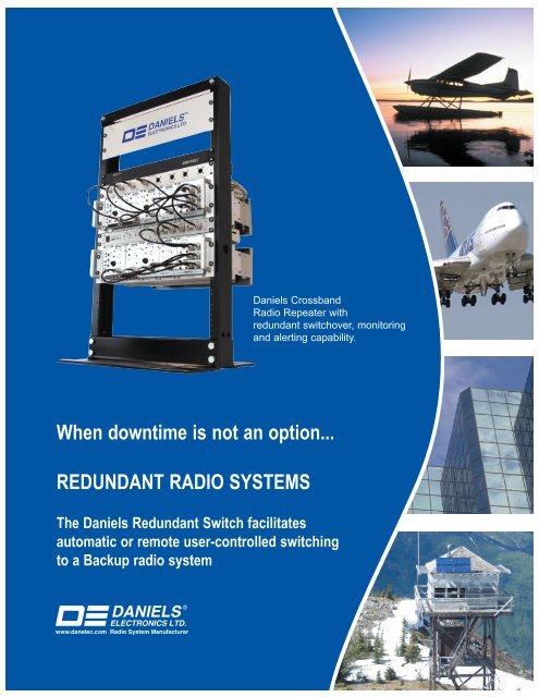
<strong>Daniels</strong> Crossband<br />
<strong>Radio</strong> Repeater with<br />
redundant switchover, monitoring<br />
and alerting capability.<br />
When downtime is not an option...<br />
REDUNDANT RADIO SYSTEMS<br />
The <strong>Daniels</strong> <strong>Redundant</strong> Switch facilitates<br />
automatic or remote user-controlled switching<br />
to a Backup radio system
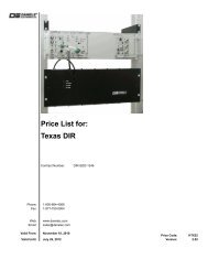
<strong>Redundant</strong> Switching: System Description<br />
Sample Application<br />
X<br />
Antenna<br />
damaged (failure)<br />
Main<br />
Antenna<br />
MAIN SYSTEM (shaded in green)<br />
connection to radio<br />
Main <strong>Radio</strong><br />
<strong>Redundant</strong> Switch<br />
Backup <strong>Radio</strong><br />
Automatic switchover after failure<br />
Backup<br />
Antenna<br />
Site Monitoring /Controlling Option:<br />
A signal is sent to a base console to alert<br />
that a switchover has occured due to a<br />
failure related to the antenna.<br />
connection to radio<br />
DUPLICATE BACKUP SYSTEM (shaded in yellow)<br />
A failure in the main system (shaded in green) causes an automatic complete switchover to the<br />
duplicate (redundant) backup system (shaded in yellow). The <strong>Redundant</strong> Switch transfers DC<br />
Power and RF signals from the Main to the Backup.<br />
Common Configurations<br />
Configuration 1: Basic <strong>Redundant</strong> Switch setup (no remote switching)<br />
This configuration consists of two <strong>Daniels</strong> radio repeaters, two power monitors and the <strong>Redundant</strong> Switch. Upon an<br />
alarm condition from the power monitors or from one of the other inputs, the <strong>Redundant</strong> Switch will automatically<br />
switch from the Main to the Backup radio. Once the system has switched to the Backup radio, it may be switched back<br />
to the Main by pushing the “Reset” button on the front panel. An optional status tone generator may be added to the<br />
Backup system to indicate that the system has been switched.<br />
Configuration 2: <strong>Redundant</strong> Switch with Remote Site Monitoring and Controlling<br />
This configuration adds a <strong>Daniels</strong> SITE/MC Site Monitor and Controller. In this configuration, the system can be<br />
remotely switched from the Main to the Backup and back again if required. The SITE/MC also allows the user to<br />
monitor alarms at a base console. This can provide the user with valuable information on which alarm has triggered the<br />
switching function before a visit to the site for maintenance.<br />
Configuration 3: Conserving battery life by turning off equipment<br />
Besides enabling Backup systems, the <strong>Redundant</strong> Switch could also be used to turn off complete racks of equipment<br />
to reduce battery drain during the winter months. Only one subrack with a monitor receiver needs to be on to receive<br />
a DTMF tone to trigger the switching.<br />
www.danelec.com
Equipment Description<br />
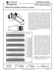
<strong>Redundant</strong> Switch<br />
The <strong>Redundant</strong> Switch is a 1U high, 19” rack mountable unit that switches DC Power and RF Inputs between radio<br />
systems. The <strong>Redundant</strong> Switch allows the Main or Backup (redundant) radio system to be selected for operation.<br />
The switching can be controlled manually via wireline or a received DTMF tone. Alternatively, it can be set up for<br />
automatic switchover via the use of various alarm modules such as the <strong>Daniels</strong> Power Monitors and/or the <strong>Daniels</strong><br />
SITE/MC Site Monitor and Controller.<br />
The <strong>Redundant</strong> Switch also has two high quality internal RF antenna relays that can be used when the user does not<br />
require a complete redundant antenna system. This relay option can combine the Main A-side radio transmitter and<br />
receiver pair into one “Antenna A” output. The B-side Main and Backup can also be combined into one “Antenna B”<br />
output.<br />
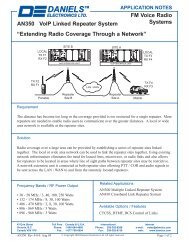
The SITE/MC & siteView Software provide the Site Monitoring & Controlling Option<br />
Site/MC<br />
The <strong>Daniels</strong> <strong>Electronics</strong> SITE/MC is a telemetry device for<br />
site monitoring, alarming and remote control. The<br />
SITE/MC monitors inputs from up to 8 analog and 8<br />
digital sensors. Commands may also be sent back to the<br />
SITE/MC to control up to 8 outputs. These outputs can<br />
trigger the <strong>Redundant</strong> Switch or other switches (e.g. a<br />
high performance relay to switch to a backup power<br />
source).<br />
SiteView Software<br />
The <strong>Daniels</strong> TASC siteView software is custom<br />
configurable (including its look and feel) and can be set to<br />
automatically poll the remote SITE/MCs at regular<br />
intervals. If a certain parameter being monitored at the<br />
radio site goes beyond a user-defined limit, an alarm can<br />
be triggered in the siteView software.<br />
www.danelec.com
<strong>Redundant</strong> Switch Specifications<br />
Operating Temperature Range: -40°C to +60°C<br />
Operating Humidity:<br />
95% RH (non-condensing) at +25°C.<br />
Operating Voltage:<br />
+13.8 Vdc Nominal (range +11.0Vdc to +17.0 Vdc)<br />
Operating Current:<br />
19mA (+/- 1.0mA)<br />
RF Relay Switching current: 200mA for 15ms max.<br />
Input Current Distribution: 40A Maximum<br />
Front Panel switches<br />
System Reset (momentary pushbutton)<br />
Backup Enable (Toggle Switch)<br />
Minimum Alarm trigger time: Active low input 25ms (6 alarm inputs)<br />
Minimum Reset trigger time: Active low input 55ms (2 reset inputs)<br />
Inputs:<br />
Outputs:<br />
• 6 active low alarm inputs (require a momentary low input from an open<br />
collector or a relay input)<br />
• 2 Reset inputs active low (momentary)<br />
• 1 Backup Test Enable/Disable (low to disable Backup Test)<br />
• 2 Alarm open collector outputs (Latched)<br />
(Alarm O/P1 low for Main indication, Alarm O/P2 low for Backup indication)<br />
Physical Dimensions: Width: 48.3 cm (19”) Height: 4.4 cm (1.75”) Depth: 22.9 cm (9.0”)<br />
Module Weight:<br />
Corrosion Prevention:<br />
External Connections:<br />
Back panel connections<br />
1.3 kg (3.0 lb.)<br />
Anodized aluminum construction. Stainless steel hardware.<br />
Glass epoxy 2 layer printed circuit boards. Gold plated module connectors.<br />
RF Connection: 6 type N connectors located on the module front panel.<br />
(Power, and Control) using 1 Phoenix screw down header and plug 12 pin<br />
connector, 3 2X8-32 Terminal Blocks.<br />
43 Erie St. Victoria BC, Canada V8V 1P8<br />
Email: sales@danelec.com<br />
Toll Free Phone: 1-800-664-4066 Toll Free Fax 1-877-750-0004<br />
Outside U.S. & Canada, Phone: 250-382-8268, Fax: 250-382-6139<br />
LIT-038-1-0-0 October 26, 2004<br />
© Copyright <strong>Daniels</strong> <strong>Electronics</strong> Ltd. All rights reserved.