warning - Braun Corporation
warning - Braun Corporation
warning - Braun Corporation

You also want an ePaper? Increase the reach of your titles
YUMPU automatically turns print PDFs into web optimized ePapers that Google loves.
®<br />
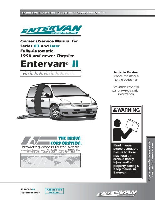
<strong>Braun</strong> Series 03 and later 1996 and newer Chrysler Entervan II<br />
ENTER<br />
Owner's/Service Manual for<br />
Series 03 and later<br />
Fully-Automatic<br />
1996 and newer Chrysler<br />
Entervan ® II<br />
®<br />
"Providing Access to the World"<br />
International Corporate Hdqrs: P.O. Box 310 Winamac, IN 46996 USA<br />
1-800-THE LIFT (219) 946-6153 FAX: (219) 946-4670<br />
5230096-03<br />
September 1996<br />
August 1998<br />
Revision<br />
TM<br />
ENTER ENTER<br />
Note to Dealer:<br />
Provide this manual<br />
to the consumer<br />
See inside cover for<br />
warranty/registration<br />
information<br />
WARNING<br />
Owner's Manual<br />
Read manual<br />
before operation.<br />
Failure to do so<br />
may result in<br />
serious bodily<br />
injury and/or<br />
property damage.<br />
Keep manual in<br />
Entervan.<br />
TM<br />
<strong>Braun</strong> Series 03 and later<br />
®<br />
1996 and newer Chrysler Entervan II
Congratulations<br />
We at The <strong>Braun</strong> <strong>Corporation</strong> wish to express our fullest appreciation<br />
on your new purchase.<br />
With you in mind, our skilled craftsmen have designed and<br />
assembled the finest lowered floor vehicle available.<br />
This manual includes operating instructions, servicing instructions,<br />
and instructions for troubleshooting, if needed.<br />
Your Entervan ® II is built for dependability, and will bring you years of<br />
pleasure and independence, as long as the maintenance is performed regularly<br />
and the Entervan ® is operated by an instructed person.<br />
•<br />
•<br />
•<br />
•<br />
Immediately upon receiving:<br />
Sincerely,<br />
Examine your Entervan ® for any damage. Notify<br />
the carrier at once with any claims.<br />
Two warranty/registration cards (shown right)<br />
are supplied with each Entervan ® . One is<br />
labeled “Dealer” and the other is labeled<br />
“Owner." The dealer must process the card<br />
labeled “Dealer." The consumer must fill out the<br />
card labeled “Owner” and mail it to The <strong>Braun</strong><br />
<strong>Corporation</strong>. Warranty details are provided in<br />
the Warranty section within this manual.<br />
THE BRAUN CORPORATION<br />
Ralph W. <strong>Braun</strong><br />
Chief Executive Officer<br />
Warranty/Registration Instructions<br />
The <strong>Braun</strong> Serial No./Series No. identification decal (shown below) is located on the Entervan ® driver's<br />
door jamb. This I.D. tag contains the product identification information provided on the Warranty/<br />
Registration card. Record the information in the space provided below. This information must be<br />
provided when filing a warranty claim or ordering parts. See the Return Authorization section<br />
for further details.<br />
1014 S. MONTICELLO P.O. BOX 310 WINAMAC, IN. 46996 219•946•6153<br />
VIN # 1B4GP54R4TB154992<br />
ENTERVAN # 5200096-03 SERIAL 1203<br />
ENG. SERIES 03 ENG. RAMP SERIES 02<br />
MFG 07/20/96 DOOR OP. SERIES 02<br />
PAINT CODE INT - DIU35799<br />
KNEELING 1 EXT - DBU5069<br />
Sample: Identification Decal<br />
Entervan ® Model No.<br />
Engineering Series No.<br />
Serial No.<br />
Engineering<br />
Series No.<br />
Entervan<br />
Model No. 5200096 - 03 - 1203 - 02 - 02 - 1<br />
Kneeling<br />
Ramp Series No.<br />
Door Operator Series No.<br />
Date of Manufacture<br />
Ramp<br />
Series No.<br />
Serial No.<br />
Door Operator<br />
Series No.<br />
Sample: Warranty/Registration Card<br />
RETAIN THIS INFORMATION FOR FUTURE USE. HAVE THIS INFORMATION WHEN FILING A<br />
WARRANTY CLAIM OR ORDERING PARTS!
Section 1: Operation<br />
Entervan II Features and Options ....................... 2, 3<br />
Safety Precautions ................................................ 4-6<br />
Pre-Operation Notes and Details<br />
Control Switches ............................................. 7-10<br />
Dash-Mounted Kneel and<br />
Open/Close Switches .................................... 8<br />
Rear Wall-Mounted Manual/Auto and<br />
Open/Close Switches .................................... 8<br />
Mini Remote Control Transmitter .................. 9<br />
Full Size Remote Control Transmitter ........... 9<br />
Passenger Door Outside Key Entry ............ 10<br />
Kneel Actuator Manual/Auto Switch ............ 10<br />
Kneeling Feature .......................................... 11, 12<br />
Automatic Power Door ........................................12<br />
Automatic Power Ramp ................................13, 14<br />
Driver Side Slide Door ........................................14<br />
Ramp Safety .......................................................15<br />
Wheelchair-Equipped Occupant Seat Belts ........15<br />
Stabilizing Wheelchairs ................................ 15, 16<br />
Wheelchair Orientation and Securement<br />
During Transport ................................................ 16<br />
Operation Procedure Review ............................. 16<br />
Preventative Maintenance ..................................17<br />
Door Locks and Anti-Theft (Alarm) System ........17<br />
Power Operating Instructions ................................18<br />
Passive Access (Non-Wheelchair) Instructions ...19<br />
Ramp Removal Instructions ............................ 20, 21<br />
Manual Operation<br />
Door and Ramp Manual<br />
Operating Instructions .................................. 21, 22<br />
Contents<br />
Kneel Actuator Manual Release<br />
Instructions .................................................. 23, 24<br />
Wheelchair and Occupant Restraint ................ 25-29<br />
Chrysler Easy-Out Roller Rear Bench Seat ........ 29<br />
Quick-Release Front Seats .............................. 30, 31<br />
Spare Tire Mount and Storage Cabinet .................32<br />
Tire Changing .................................................... 32, 33<br />
Section 2: Maintenance<br />
Maintenance and Lubrication Schedule .......... 34-36<br />
Section 3: Troubleshooting<br />
Troubleshooting Diagnosis Chart .................... 37-42<br />
Auxiliary Power Supply for Dealer-Installed<br />
Power Seat or Tie-Down ......................................... 44<br />
Wiring Diagram (Fold Out) ........................... 45A, 46A<br />
Electrical Schematic (Fold Out) .................. 45B, 46B<br />
Section 4: Repair Parts<br />
Power Door Operator Assembly ............................47<br />
Power Ramp Motor Assembly ............................... 48<br />
Ramp Assembly ...................................................... 49<br />
Kneel Actuator Assembly ...................................... 50<br />
Kneel Actuator Manual Release<br />
Lever Assembly ...................................................... 51<br />
Passenger Door Outside Key Entry Assembly .... 51<br />
Decals ................................................................. 52-57<br />
Section 5: Specifications and Dimensions<br />
Specifications ......................................................... 58<br />
Dimensions ............................................................. 59<br />
Section 6: Warranty<br />
Warranty ............................................................ 60, 61<br />
Return Authorization Procedure ........................... 61<br />
Page 1<br />
Operation Maintenance<br />
Troubleshooting Repair Parts Specifications & Dimensions Warranty
Operation<br />
Standard Features:<br />
Page 2<br />
Entervan II Features and Options<br />
Normal (Non-Kneeled) Position Kneeled (Lowered) Position<br />
The <strong>Braun</strong> Series 03 1996 and newer Chrysler Entervan II<br />
conversion offers the following standard features in<br />
addition to the Chrysler Mini-Van chassis equipment.<br />
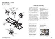
Electromechanical Power Kneeling Rear Suspension<br />
with On/Off and Override Features: “Kneeling” is<br />
the lowering and raising motion of the Entervan electromechanical<br />
rear suspension (shown above). The kneel<br />
feature reduces the slope of the ramp when deployed. A<br />
Kneel On/Off Switch, an Out-of-Park Override and a<br />
Mechanical Override are incorporated in the electromechanical<br />
power kneeling system. See pages 11 and 12<br />
for further details.<br />
Power Slide Door with Manual Release Feature:<br />
The power door and lowered floor configuration provides<br />
52-3/4" clear vertical passageway. See page 12 for<br />
details.<br />
Removable Power Ramp with Manual Release<br />
Feature and Passive Access Feature: See pages 13<br />
and 14 for further details.<br />
Passive (Non-Wheelchair) Access: This feature<br />
allows passive (non-wheelchair) access to the passenger<br />
side slide door opening when desired. See page 19 for<br />
further details.<br />
Lowered Floor from Rear Axle to Firewall: This<br />
feature provides additional headroom (57-1/2" floor-toceiling<br />
at center of van), and further reduces the slope of<br />
the power ramp when deployed. See Position C in the<br />
illustration and photos on the opposite page.<br />
Lowered Driver-Side Second Sliding Door: The<br />
<strong>Braun</strong> <strong>Corporation</strong> Entervan II conversion is available for<br />
Chrysler Mini-Van chassis equipped with the driver-side<br />
second sliding door option only.<br />
Quick-Release Driver Seat: For the wheelchair<br />
occupant who chooses to drive the Entervan II, this seat<br />
(Position A) can be removed and adaptive driving<br />
Power Slide Door Power Ramp<br />
systems custom tailored for the individual can be purchased<br />
from and installed by your local dealer. 56" floorto-ceiling<br />
headroom is provided at this seating position.<br />
See pages 30 and 31 for seat removal and installation<br />
instructions.<br />
Quick-Release Front Passenger Seat with Floor<br />
Track for Wheelchair and Occupant Securement: This<br />
seat (Position B) can be removed and the seat location<br />
can be utililized by a wheelchair occupant. 56" floor-toceiling<br />
headroom is provided at this seating position.<br />
Floor Track for Wheelchair and Occupant Securement<br />
in Mid-Point Lowered Floor Area: Floor track<br />
provided in the mid-point lowered floor area (Position C)<br />
can be utililized for restraint of wheelchair passenger(s).<br />
Wheelchair capacity at mid-point may have limitations<br />
based on the physical dimensions of specific wheelchairs.<br />
See pages 25-29 for details and instructions for wheelchair<br />
and occupant restraint.<br />
Forward-Facing Wheelchair and Occupant Belt/<br />
Track System: One Forward-Facing Wheelchair and<br />
Occupant Belt Kit is supplied for the restraint of one<br />
wheelchair and occupant only. Additional belt kits can be<br />
purchased. The belt kit is used in conjunction with the<br />
floor track. See pages 25-29 for details and instructions<br />
for wheelchair and occupant restraint.<br />
Easy-Out Roller 3-Passenger Bench Seat at Rear<br />
of Vehicle: See page 29 for further details.<br />
Auxiliary Power Supply for Dealer-Installed Power<br />
Seat or Electric Tie-Downs: See page 44 for details.<br />
Interior Spare Tire Mount/Storage Cabinet: See<br />
pages 32 and 33 for details.<br />
Color-Coded Control Switches: Color-coded and<br />
function-labeled control switches that correspond to the<br />
color coding and switch function labels which appear on<br />
the Power Operation Instructions decal are provided
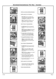
Wheelchair Positions<br />
A<br />
C<br />
Wheelchair Seating Positions: Wheelchair<br />
passengers shown depict the available<br />
wheelchair seating positions. Wheelchair<br />
capacity at mid-point (Position C) may have<br />
limitations based on the physical dimensions<br />
of specific wheelchairs.<br />
B<br />
Entervan II Features and Options<br />
Horizontal<br />
“A” Track<br />
Horizontal<br />
“A” Track<br />
inside the Entervan (dash and rear wall locations).<br />
See pages 7-10 for details.<br />
Remote Control: Two mini remote control<br />
transmitters are supplied for automatic operation<br />
of kneeling, door and ramp functions. See page 9<br />
for details.<br />
Passenger Door Outside Key Entry System:<br />
An outside key entry incorporated in the front<br />
passenger side door lock activates the automatic<br />
operation of kneeling, door and ramp functions as<br />
well as operating the passenger door lock. See<br />
page 10 for details.<br />
Dash-Mounted Control Switches<br />
Rear Wall-Mounted<br />
Control Switches<br />
A<br />
C<br />
Mid-Point<br />
Horizontal “A” Track<br />
C<br />
Mid-Point<br />
Horizontal “A” Track<br />
B<br />
Easy-Out ® 3-Passenger<br />
Bench Seat<br />
Power Ramp Operator Horizontal “A” Track<br />
Options:<br />
• Extra Wheelchair and Occupant Securement System<br />
• Full Size Remote Control Transmitter<br />
• Extra Mini Remote Control Transmitter<br />
• Remote Start<br />
Page 3<br />
Operation
Operation<br />
Safety Symbols<br />
SAFETY FIRST! Know That....<br />
A<br />
All information contained<br />
in this manual and supplements<br />
(if included) is provided<br />
for your safety. Familiarity with<br />
proper operation instructions<br />
as well as proper maintenance<br />
procedures are necessary to<br />
ensure safe, troublefree<br />
operation. Safety precautions<br />
are provided to identify potentially<br />
hazardous situations and<br />
provide instruction on how to<br />
avoid them.<br />
D<br />
Page 4<br />
Safety Precautions<br />
Note: Additional information provided to help clarify or detail a specific subject.<br />
C CAUTION<br />
This symbol indicates<br />
important information<br />
regarding how to<br />
avoid a hazardous<br />
situation that could<br />
result in minor personal<br />
injury or property<br />
damage.<br />
These symbols will appear throughout this manual as well as on the labels posted on your Entervan.<br />
Recognize the seriousness of this information.<br />
Safety Precautions<br />
WARNING<br />
If the operating<br />
instructions, manual<br />
operating instructions<br />
and/or safety precautions<br />
are not fully<br />
understood, contact<br />
The <strong>Braun</strong> <strong>Corporation</strong><br />
immediately.<br />
Failure to do so may<br />
result in serious<br />
bodily injury and/or<br />
property damage.<br />
WARNING<br />
WARNING<br />
WARNING<br />
WARNING<br />
WARNING<br />
B<br />
WARNING<br />
WARNING<br />
WARNING<br />
WARNING<br />
WARNING<br />
This symbol indicates<br />
important safety information<br />
regarding a<br />
potentially hazardous<br />
situation that could<br />
result in serious<br />
bodily injury and/or<br />
property damage.<br />
Read this manual, supplement(s) and the Chrysler-supplied<br />
vehicle owner's manual before operation. Read and become<br />
familiar with all safety precautions, pre-operation notes and<br />
details, operating instructions and manual operating instructions<br />
before operation. Note: Wheelchair passengers,<br />
wheelchair attendants, Entervan drivers and Entervan<br />
operators must read and become familiar with the contents<br />
of this manual and supplement(s) before operation.<br />
Load and unload on level surface only.<br />
Engage vehicle parking brake before operation.<br />
Provide adequate clearance outside the vehicle to accommodate<br />
the ramp.<br />
Do not operate Entervan if you suspect damage, wear or any abnormal condition.<br />
Keep clear of area in which the door and ramp operate.<br />
Close driver-side slide door before loading and unloading wheelchair passengers.<br />
Wheelchair passengers must position and secure (buckle, engage, fasten, etc.) the<br />
wheelchair-equipped occupant seat belt before loading onto the wheelchair ramp.<br />
Be aware of the Entervan ramp slope (angle).
WARNING<br />
WARNING<br />
WARNING<br />
WARNING<br />
WARNING<br />
WARNING<br />
WARNING<br />
WARNING<br />
WARNING<br />
WARNING<br />
WARNING<br />
WARNING<br />
WARNING<br />
WARNING<br />
WARNING<br />
WARNING<br />
WARNING<br />
WARNING<br />
WARNING<br />
WARNING<br />
WARNING<br />
WARNING<br />
WARNING<br />
WARNING<br />
Safety Precautions<br />
Do not board an Entervan ramp if you or your attendant are intoxicated.<br />
The wheelchair must be positioned in the center of the ramp when loading and unloading.<br />
Load and unload clear of vehicular traffic.<br />
Keep clear of area in which the vehicle kneels (lowers).<br />
Do not activate control switches when anyone is near the area in which door operates,<br />
ramp operates or vehicle kneels.<br />
Do not disengage vehicle transmission from Park “P” when a wheelchair passenger is on<br />
the ramp.<br />
Do not press KNEEL switch to NO position when a wheelchair passenger is on the ramp.<br />
Do not overload or abuse the ramp. The design load capacity is 600 pounds.<br />
Do not grip detachable wheelchair parts when assisting to stabilize wheelchair.<br />
Do not drive Entervan with the rear of the vehicle in the kneeled (lowered) position.<br />
Keep this manual and the Chrysler-supplied vehicle manual in the Entervan at all times.<br />
Replace missing, worn or illegible decals.<br />
Do not remove any guards or covers.<br />
Do not use accessory devices* not authorized by The <strong>Braun</strong> <strong>Corporation</strong>.<br />
Do not use an Entervan for towing. Towing with an Entervan is prohibited.<br />
Do not install a raised top kit on an Entervan.<br />
Never modify (alter) a <strong>Braun</strong> <strong>Corporation</strong> Entervan.<br />
Manual Operation<br />
Clear ramp path before performing manual unfold procedures. Ramp will free-fall.<br />
Be certain door is fully open when manually unfolding and folding the ramp during manual<br />
operating procedures.<br />
Keep clear of moving parts when manually operating door and/or ramp.<br />
Remote Control<br />
Be aware of the location and condition of the remote control transmitter at all times.<br />
Accidental activation of switches may cause unintended operation.<br />
Do not operate remote control unit with anyone on the ramp or near the area in which door<br />
operates, ramp operates or vehicle kneels.<br />
Discontinue remote control use immediately if any unexplained and/or improper operation<br />
occurs. Contact your dealer or call The <strong>Braun</strong> <strong>Corporation</strong> at 1-800-THE LIFT.<br />
Do not interface after-market control systems* with a <strong>Braun</strong> Entervan.<br />
* See page 6 for The <strong>Braun</strong> <strong>Corporation</strong> After-Market Control Systems Policy.<br />
Page 5<br />
Operation
Operation<br />
Page 6<br />
WARNING<br />
If the operating<br />
instructions, manual<br />
operating instructions<br />
and/or safety precautions<br />
are not fully<br />
understood, contact<br />
The <strong>Braun</strong> <strong>Corporation</strong><br />
immediately.<br />
Failure to do so may<br />
result in serious<br />
bodily injury and/or<br />
property damage.<br />
WARNING<br />
WARNING<br />
WARNING<br />
WARNING<br />
WARNING<br />
WARNING<br />
WARNING<br />
WARNING<br />
WARNING<br />
WARNING<br />
Safety Precautions<br />
Wheelchair and Occupant Restraint<br />
No product developed to date can guarantee successful<br />
securement of the wheelchair, even at low speeds, in the<br />
event of an accident. The <strong>Braun</strong> Wheelchair and Occupant<br />
Belt/Track System does meet the most widely referenced<br />
Federal Motor Vehicle Safety Standards used for contemporary<br />
restraint equipment. However, this equipment does not<br />
ensure stability of the wheelchair in the event of an accident<br />
at any speed.<br />
The Wheelchair and Occupant Belt/Track System supplied<br />
with this unit must be utilized as specified within this manual.<br />
Read and become familiar with all Forward-Facing Wheelchair<br />
and Occupant Belt/Track System Instructions as<br />
specified in this manual prior to installation or operation<br />
procedures. If the instructions are not fully understood,<br />
contact The <strong>Braun</strong> <strong>Corporation</strong> immediately.<br />
When using wheelchair restraints not supplied with the Entervan, read and become familiar<br />
with all installation and operation instructions supplied with your particular wheelchair<br />
restraint system prior to installation or operation procedures. If the instructions are not fully<br />
understood, contact the manufacturer immediately.<br />
Non-Wheelchair Passenger Restraint<br />
Observe all local, state and federal laws for specific seat belt usage requirements.<br />
Refer to Chrysler-supplied owner's manual for instructions regarding passenger (children<br />
and adults) restraints.<br />
Quick-Release Front Seats<br />
Quick-release front seat securement devices must be fully engaged before occupying<br />
seats or operating vehicle.<br />
Chrysler Easy-Out Roller Seats<br />
Install, remove and operate Chrysler<br />
Easy-Out Roller seats as detailed in<br />
Chrysler owner's manual.<br />
Tire Changing and Jacking<br />
Follow all jacking and tire changing<br />
instructions and safety precautions in the<br />
Chrysler-supplied owner's manual when<br />
changing a flat tire or raising the vehicle.<br />
All Precautions<br />
Failure to follow these safety precautions<br />
may result in serious bodily injury and/or<br />
property damage.<br />
<strong>Braun</strong> <strong>Corporation</strong> After-Market<br />
Control Systems Policy<br />
The <strong>Braun</strong> <strong>Corporation</strong> manufactures<br />
dedicated control systems for it's products<br />
(i.e., wheelchair lifts, door operators, ramp<br />
systems, kneeling systems). These control<br />
systems have been designed and tested for<br />
use in conjunction with specific <strong>Braun</strong><br />
products. <strong>Braun</strong> control systems are the<br />
only control systems authorized for use with<br />
<strong>Braun</strong> products. Do not attempt to interface<br />
after-market control systems with <strong>Braun</strong><br />
products. To do so may result in serious<br />
bodily injury and/or property damage.<br />
For information about the proper control<br />
system for a specific <strong>Braun</strong> product, contact<br />
The <strong>Braun</strong> <strong>Corporation</strong> at 1-800-THE LIFT.
WARNING<br />
Read and become<br />
familiar with all safety<br />
precautions, preoperation<br />
notes and<br />
details, operating<br />
instructions and<br />
manual operating<br />
instructions prior to<br />
operation. Contact<br />
The <strong>Braun</strong> <strong>Corporation</strong><br />
immediately if<br />
this information is not<br />
fully understood.<br />
Failure to do so may<br />
result in serious<br />
bodily injury and/or<br />
property damage.<br />
Control Switches<br />
Color Coding: Entervan II<br />
interior-mounted control switches<br />
are color-coded and functionlabeled<br />
to correspond to the color<br />
coding and switch-function labels<br />
that appear on the Power Operation<br />
Instructions decal (posted on<br />
the interior wall panel above the<br />
power door operator).<br />
The color of the symbol corresponds<br />
to the color of the switch<br />
to be used. Color coding applies<br />
to the interior-mounted control<br />
switches only.<br />
Triangular-shaped color-coded<br />
symbols appear on the Power<br />
Operation Instructions decal. The<br />
direction of the symbol corresponds<br />
with the direction the<br />
switch should be activated<br />
(pressed) to produce the intended<br />
Pre-Operation Notes and Details<br />
The Entervan II provides fully<br />
automatic operation of the<br />
electromechanical “kneeling”<br />
system, the passenger side slide<br />
door and the ramp. Refer to<br />
Entervan II Features and Options<br />
(pages 2 and 3), and referenced<br />
sections in this manual for<br />
identification and explanation of<br />
Entervan features and functions.<br />
Terminology: The term<br />
“KNEEL” appearing within this<br />
manual and on operating instructions<br />
decals is a reference to the<br />
lowering and raising motion of the<br />
Entervan electromechanical rear<br />
function. = Press switch UP,<br />
and = press switch DOWN.<br />
Although the remote control<br />
transmitter OPEN and CLOSE<br />
switches are not color-coded,<br />
the functions activated by remote<br />
control transmitter OPEN and<br />
CLOSE switches are identical to<br />
the functions activated by the<br />
interior-mounted OPEN/CLOSE<br />
switches.<br />
The outside key entry activates<br />
the same functions as the interiormounted<br />
yellow OPEN/CLOSE<br />
switches and the remote control<br />
transmitter OPEN and CLOSE<br />
switches.<br />
Control switch details are provided<br />
in this section.<br />
suspension. The term “OPEN”<br />
indicates the opening motion of<br />
the power slide door, and<br />
“CLOSE” indicates the closing<br />
motion of the power slide door.<br />
The term “UNFOLD” indicates the<br />
lowering motion of the ramp to<br />
the deployed position. The term<br />
“FOLD” indicates the raising<br />
motion of the ramp to the vertical<br />
(stowed) position.<br />
Contact The <strong>Braun</strong> <strong>Corporation</strong><br />
immediately if any of this information<br />
is not understood. Call 1-<br />
800-THE LIFT.<br />
WARNING<br />
Do not activate<br />
control switches when<br />
anyone is near the<br />
area in which door<br />
operates, ramp<br />
operates or vehicle<br />
kneels. Failure to<br />
follow this rule may<br />
result in serious<br />
bodily injury and/or<br />
property damage.<br />
Page 7<br />
Operation
Operation<br />
Control Switches (continued)<br />
Dash-Mounted Control Switches<br />
Yellow OPEN/CLOSE Switch<br />
Press the yellow OPEN/CLOSE<br />
switch to the CLOSE (up) position<br />
to fold (raise) the ramp, close<br />
the automatic door and activate<br />
the “kneel” system*.<br />
Press the yellow OPEN/CLOSE<br />
switch to the OPEN (down)<br />
position to open the automatic<br />
door, unfold (lower) the ramp and<br />
activate the “kneel” system*.<br />
Rear Wall-Mounted Control Switches<br />
Yellow OPEN/CLOSE Switch<br />
Press the yellow OPEN/CLOSE<br />
switch to the CLOSE (up)<br />
position to fold (raise) the ramp,<br />
close the automatic door and<br />
activate the “kneel” system*.<br />
Press the yellow OPEN/CLOSE<br />
switch to the OPEN (down)<br />
position to open the automatic<br />
door, unfold (lower) the ramp and<br />
activate the “kneel” system*.<br />
Page 8<br />
Pre-Operation Notes and Details<br />
See page 11 for overall view of<br />
dash-mounted control switches.<br />
Control Switches<br />
(Detail Photo Below)<br />
* The KNEEL switch turns the<br />
“kneeling” system on and off<br />
only. Pressing the OPEN/<br />
CLOSE switch automatically<br />
activates the “kneeling” feature<br />
to lower the vehicle if the red<br />
dash-mounted KNEEL switch<br />
is in the YES (up) position.<br />
Pressing the CLOSE switch<br />
activates the “kneeling” feature<br />
to raise the vehicle if the red<br />
dash-mounted KNEEL switch<br />
is in the YES (up) position.<br />
Red KNEEL Switch:<br />
Press the red KNEEL switch to<br />
the YES (up) position to turn<br />
the “kneel” system* on.<br />
Press the red KNEEL switch to<br />
the NO (down) position to turn<br />
the “kneel” system* off.<br />
MANUAL/AUTO Override<br />
Switch: This switch must be<br />
pressed to the AUTO position<br />
before automatic (power) ramp<br />
functions can be activated.<br />
Pressing this switch to the<br />
MANUAL position allows the<br />
power ramp to be manually<br />
operated in event of power or<br />
equipment failure. This switch<br />
must be in the MANUAL position<br />
when performing Manual Ramp<br />
Operating Procedures.<br />
OPEN/CLOSE Switch: This<br />
switch is identical to the dashmounted<br />
OPEN/CLOSE switch in<br />
appearance and operation.<br />
Black MANUAL/AUTO Switch<br />
Press the black MANUAL/AUTO<br />
switch to the MANUAL (up)<br />
position before performing<br />
Manual Ramp Operating Procedures.<br />
Press the black MANUAL/AUTO<br />
switch to the AUTO (down)<br />
position before performing<br />
automatic Power Operating<br />
Procedures.
Mini Remote Control Transmitter Switches<br />
The remote control OPEN and<br />
CLOSE switches activate the<br />
same functions as the Entervanmounted<br />
yellow OPEN/CLOSE<br />
switches. Two mini remote<br />
control transmitters (shown here)<br />
are supplied with all Entervans.<br />
Press the OPEN switch to open<br />
the automatic door and unfold<br />
(lower) the ramp. Note: Pressing<br />
the OPEN switch also activates<br />
the “kneeling” feature to<br />
lower the vehicle if the red dashmounted<br />
KNEEL switch is in the<br />
YES (up) position.<br />
The <strong>Braun</strong> <strong>Corporation</strong> manufactures<br />
dedicated control<br />
systems for it's products (i.e.,<br />
wheelchair lifts, door operators,<br />
ramp systems, kneeling systems).<br />
These control systems<br />
have been designed and tested<br />
for use in conjunction with<br />
The remote control OPEN and<br />
CLOSE switches activate the<br />
same functions as the Entervanmounted<br />
yellow OPEN/CLOSE<br />
switches. The full size remote<br />
control transmitter (shown here)<br />
is available as an option only.<br />
Press the OPEN switch to open<br />
the automatic door and unfold<br />
(lower) the ramp. Note: Pressing<br />
the OPEN switch also activates<br />
the “kneeling” feature to<br />
lower the vehicle if the red dashmounted<br />
KNEEL switch is in the<br />
YES (up) position.<br />
Pre-Operation Notes and Details<br />
OPEN CLOSE<br />
19968<br />
WARNING<br />
Read manual before operating.<br />
Do not operate this control unit<br />
with anyone on or near the area<br />
in which the ramp operates or<br />
the vehicle kneels (lowers).<br />
Failure to follow these rules<br />
may result in serious bodily<br />
injury and/or property damage.<br />
19969<br />
Do not interface aftermarket<br />
control systems**<br />
with a <strong>Braun</strong> Entervan.<br />
** <strong>Braun</strong> <strong>Corporation</strong> After-Market Control Systems Policy:<br />
specific <strong>Braun</strong> products. <strong>Braun</strong><br />
control systems are the only<br />
control systems authorized for<br />
use with <strong>Braun</strong> products.<br />
Do not attempt to interface aftermarket<br />
control systems with<br />
<strong>Braun</strong> products. To do so may<br />
Full Size Remote Control Transmitter (Option) Switches<br />
OPEN CLOSE 18563<br />
ENTER<br />
Remote Control Unit<br />
WARNING<br />
18564<br />
Read manual before operating. Do<br />
not operate this control unit with<br />
anyone on or near the area in which<br />
the ramp operates or the vehicle<br />
kneels (lowers). Failure to follow<br />
these rules may result in serious<br />
bodily injury and/or property damage.<br />
Do not interface aftermarket<br />
control systems**<br />
with a <strong>Braun</strong> Entervan.<br />
TM<br />
Note: A full size (larger) remote<br />
control transmitter (shown below) is<br />
available as an option. Operation<br />
procedures for both transmitters<br />
are identical. The remote control<br />
system has an operating range of<br />
35 feet.<br />
Press the CLOSE switch to fold<br />
(raise) the ramp and close the<br />
automatic door. Note: Pressing<br />
the CLOSE switch also activates<br />
the “kneeling” feature to raise the<br />
vehicle if the red dash-mounted<br />
KNEEL switch is in the YES (up)<br />
position.<br />
result in serious bodily injury<br />
and/or property damage.<br />
For information about the<br />
proper control system for a<br />
specific <strong>Braun</strong> product, contact<br />
The <strong>Braun</strong> <strong>Corporation</strong> at 1-<br />
800-THE LIFT.<br />
Note: Two mini remote control<br />
transmitters (shown above) are<br />
supplied with all Entervans. Operation<br />
procedures for both transmitters<br />
are identical. The remote<br />
control system has an operating<br />
range of 35 feet.<br />
Press the CLOSE switch to fold<br />
(raise) the ramp and close the<br />
automatic door. Note: Pressing<br />
the CLOSE switch also activates<br />
the “kneeling” feature to raise the<br />
vehicle if the red dash-mounted<br />
KNEEL switch is in the YES (up)<br />
position.<br />
Page 9<br />
Operation
Operation<br />
Control Switches (continued)<br />
Passenger Door Outside Key Entry<br />
An outside key entry is incorporated<br />
in the passenger side front<br />
door lock. The outside key entry<br />
activates the same functions as<br />
the interior-mounted yellow<br />
OPEN/CLOSE switches and the<br />
remote control transmitter OPEN<br />
and CLOSE switches. The<br />
vehicle OEM door key activates<br />
the outside key entry system as<br />
well as operating the passenger<br />
door lock. See your Chrysler<br />
owner's manual for details<br />
regarding door locks.<br />
CLOSE: Insert the key and turn it<br />
counterclockwise (toward rear of<br />
vehicle) to fold (raise) the ramp<br />
and close the automatic door.<br />
Note: Turning the key counterclockwise<br />
also activates the<br />
“kneeling” feature to raise the<br />
vehicle if the red dash-mounted<br />
KNEEL switch is in the YES (up)<br />
position.<br />
Kneel Actuator MANUAL/AUTO Switch<br />
The Kneel Actuator MANUAL/<br />
AUTO switch is mounted in the<br />
Kneel Actuator Manual Release<br />
assembly. The Kneel Actuator<br />
Manual Release assembly is<br />
located behind the driver's side<br />
slide door. This switch must be<br />
Kneel Actuator MANUAL/AUTO Switch<br />
Press the black MANUAL/AUTO<br />
switch to the MANUAL (up) position<br />
before performing Kneel Actuator<br />
Manual Release Procedures.<br />
Press the black MANUAL/AUTO<br />
switch to the AUTO (down)<br />
position before performing automatic<br />
Power Kneeling Operations.<br />
Page 10<br />
Pre-Operation Notes and Details<br />
Delay Feature: When activating<br />
the OPEN functions using the<br />
outside key entry, the key unlocks<br />
the door and then there is a two<br />
second delay before the Entervan<br />
power functions are activated.<br />
This delay feature only<br />
occurs when activating the<br />
outside key entry and only occurs<br />
during the OPEN function.<br />
CLOSE<br />
OPEN<br />
in the AUTO position before the<br />
electromechanical power kneeling<br />
system can be activated. The<br />
MANUAL/AUTO switch must be<br />
pressed to the MANUAL position<br />
in order to manually release the<br />
kneel actuator.<br />
MANUAL<br />
AUTO<br />
OPEN: Insert the key and turn it<br />
clockwise (toward front of vehicle)<br />
to open the automatic door and<br />
unfold (lower) the ramp. Note:<br />
Turning the key clockwise also<br />
activates the “kneeling” feature to<br />
lower the vehicle if the red dashmounted<br />
KNEEL switch is in the<br />
YES (up) position.<br />
Do not press this switch to the<br />
MANUAL position unless you<br />
have experienced kneel actuator<br />
power or equipment failure. See<br />
pages 23 and 24 for further details.<br />
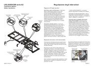
Kneel Actuator Manual Release<br />
Assembly<br />
MANUAL<br />
AUTO<br />
KNEEL ACTUATOR<br />
MANUAL RELEASE<br />
Use only if vehicle will not<br />
raise electrically.<br />
1. Press MANUAL/AUTO switch<br />
to MANUAL position.<br />
2. Pull detent pin.<br />
3. Pull red handled lever fully.<br />
4. Insert detent pin in lever hole.<br />
Note: Pull detent pin, return lever<br />
to original position and press<br />
MANUAL/AUTO switch to AUTO<br />
position before performing electric<br />
procedures.<br />
52215
Whenever parking your<br />
Entervan and before utilizing<br />
any Entervan features, always<br />
engage the vehicle transmission<br />
in Park “P” and engage<br />
the vehicle parking brake.<br />
Transmission: The vehicle<br />
transmission must be engaged<br />
in Park “P,” before operating<br />
the Entervan automatic features.<br />
Entervan power function<br />
control switches cannot be<br />
activated if the vehicle transmission<br />
is not in Park.<br />
MANUAL/AUTO Override<br />
Switch: The MANUAL/AUTO<br />
Kneeling Feature<br />
“Kneeling” is the lowering and<br />
raising motion of the Entervan<br />
electromechanical rear suspension.<br />
The kneel feature lowers<br />
the rear of the vehicle. See the<br />
photos on page 2.<br />
The Entervan operator has the<br />
option of using the kneel<br />
feature or not. Activating the<br />
kneel feature to lower the rear<br />
of the vehicle reduces the slope<br />
of the ramp when deployed.<br />
WARNING<br />
Keep clear of area<br />
in which the vehicle<br />
kneels (lowers).<br />
Failure to do so may<br />
result in serious<br />
bodily injury.<br />
Do not activate the kneel<br />
system when anyone is near<br />
the underside of the vehicle.<br />
Kneel (lower) the Entervan<br />
on level surfaces only.<br />
Pre-Operation Notes and Details<br />
override switch must be<br />
pressed to the AUTO<br />
position before the automatic<br />
ramp can be activated.<br />
This switch is<br />
located on the passengerside<br />
interior wall panel,<br />
above the power door<br />
operator as shown at right.<br />
See Control Switches on<br />
page 8 also.<br />
Kneel Actuator MANUAL/<br />
AUTO Switch: The Kneel<br />
Actuator MANUAL/AUTO<br />
switch must be pressed to the<br />
AUTO position before the electromechanical<br />
“kneeling” system can<br />
The red dash-mounted KNEEL<br />
switch turns the “kneeling” system<br />
on and off. This switch provides<br />
the option of kneeling the vehicle<br />
when operating the power door<br />
and power ramp. The optional<br />
“kneeling” feature can only be<br />
turned on and off by the dashmounted<br />
red KNEEL switch. See<br />
Control Switches on page 8.<br />
Press the red KNEEL switch to<br />
the YES position to turn the<br />
“kneel” system on. Press the red<br />
KNEEL switch to the NO position<br />
to turn the “kneel” system off.<br />
With the KNEEL switch in the<br />
YES position, the rear of the<br />
vehicle will automatically lower<br />
when either of the two interiormounted<br />
yellow OPEN/CLOSE<br />
switches is pressed to the OPEN<br />
position for two seconds or<br />
longer.<br />
Delay Feature: The OPEN<br />
switch must be pressed for two<br />
seconds or longer before the<br />
“kneel” system is activated. Once<br />
the “kneel” system is activated,<br />
MANUAL/AUTO<br />
Override Switch<br />
be activated. See photos and<br />
details on opposite page.<br />
Red Kneel Switch<br />
the rear of the Entervan will continue<br />
to lower regardless if one of<br />
the control switches is continued to<br />
be pressed.<br />
Pressing the remote control OPEN<br />
switch or turning the passenger<br />
door outside key entry key clockwise<br />
(toward front of vehicle)<br />
activates the “kneel” function in the<br />
same manner.<br />
Page 11<br />
Operation
Operation<br />
Kneeling Feature (continued)<br />
When the red KNEEL switch is in the YES position,<br />
the vehicle will automatically raise when either of the<br />
two Entervan-mounted yellow OPEN/CLOSE<br />
switches are pressed to the CLOSE position.<br />
Pressing the remote control CLOSE switch or<br />
turning the passenger door outside key entry key<br />
counterclockwise (toward rear of vehicle) activates<br />
the “kneel” function to raise the rear of the Entervan<br />
in the same manner.<br />
Note: If the vehicle is in the kneeled position and<br />
the red KNEEL switch is pressed to the NO position,<br />
the rear of the vehicle will raise automatically. Do<br />
not press the KNEEL switch to the NO position<br />
when a wheelchair passenger is on the ramp!<br />
Out-of-Park Kneeling Override: If the Entervan is<br />
in the kneeled position and the vehicle transmission<br />
is disengaged from Park “P,” the rear of the vehicle<br />
will automatically raise. This feature eliminates<br />
the possibility of unintentionally driving the Entervan<br />
with the rear of the vehicle in the lowered position.<br />
When the transmission is disengaged from Park, the<br />
kneel actuator is electrically activated. When<br />
activated, the actuator shaft extends to raise the<br />
rear of the vehicle to the normal position. Do not<br />
disengage the transmission from Park when a<br />
Automatic Power Door<br />
Page 12<br />
WARNING<br />
Keep clear of area in<br />
which the door<br />
operates. Failure to<br />
do so may result in<br />
serious bodily injury.<br />
Pre-Operation Notes and Details<br />
Keep clear of area<br />
in which the automatic<br />
power door<br />
operates. Be<br />
certain no person or<br />
obstruction is within<br />
the path of the door<br />
when opening or<br />
closing the door.<br />
Keep children clear of the door and ramp paths<br />
(operating areas) during door and ramp operation.<br />
Keep body parts and obstructions clear of<br />
area in which door operates. Keep clear of all<br />
power door moving parts. Do not place any<br />
body part or obstruction in the path of the<br />
automatic door, the door gear rack or other<br />
power door moving parts. Do not attempt to<br />
grip or hold the door or door gear rack.<br />
wheelchair passenger is on the ramp!<br />
Mechanical Kneeling Override: In the event that<br />
the Entervan is in the kneeled position and you<br />
experience power or equipment failure, the Kneel<br />
Actuator Manual Release (Override) feature allows<br />
the rear of the vehicle to be raised to the normal<br />
position. Further details and Kneel Actuator Manual<br />
Release Instructions are provided on pages 23 and<br />
24.<br />
Do not continue to<br />
drive the Entervan<br />
with the rear of the<br />
vehicle in the lowered<br />
position. Attempting<br />
to drive the Entervan<br />
with the rear of the<br />
vehicle in the lowered<br />
position will result in an<br />
extremely rough and<br />
unstable ride, and<br />
WARNING<br />
Driving an Entervan<br />
in the kneeled (lowered)<br />
position may<br />
result in serious<br />
bodily injury and/or<br />
property damage.<br />
could possibly result in injury and/or vehicle<br />
damage. The vehicle would ride as if it did not have<br />
any rear suspension. In the event of a kneel<br />
system failure, have the kneel system repaired<br />
immediately.<br />
The automatic door can be activated by either<br />
interior-mounted yellow OPEN/CLOSE switch, the<br />
remote control switches or the passenger door<br />
outside key entry. See pages 7-9 for further details<br />
regarding these Entervan controls.<br />
You must continue to press the OPEN switch or<br />
turn the outside key entry key clockwise throughout<br />
the entire door opening function (until the door<br />
stops - opens fully). You must continue to press<br />
the CLOSE switch or turn the outside key entry key<br />
counterclockwise throughout the entire door closing<br />
function to close the door fully.<br />
Manual Operation: If you experience power or<br />
equipment failure, refer to the Door and Ramp<br />
Manual Operating Instructions on pages 21 and 22.
Automatic Power Ramp<br />
WARNING<br />
Provide adequate<br />
clearance outside of<br />
vehicle to accommodate<br />
ramp.<br />
Failure to do so may<br />
result in serious<br />
bodily injury and/or<br />
property damage.<br />
Pre-Operation Notes and Details<br />
Be certain there is<br />
adequate clearance<br />
outside the Entervan<br />
before unfolding the<br />
automatic ramp.<br />
Approximately 56<br />
inches clearance<br />
must be provided to<br />
accommodate the<br />
ramp.<br />
Keep clear of area in which the automatic power<br />
ramp operates. Be certain no person or obstruction<br />
is within the path of the ramp when unfolding or<br />
folding the ramp.<br />
Keep all passengers and bystanders clear of the<br />
area in which the ramp unfolds and folds (inside and<br />
outside the vehicle). Keep children clear of the<br />
ramp path (operating area) during ramp operation.<br />
When inside the vehicle, all non-wheelchair<br />
passengers should be seated and restrained using<br />
the Chrysler-equipped (OEM) seat belts as detailed<br />
Do not grip or hold<br />
ramp fold arm!<br />
WARNING<br />
Keep body parts<br />
and obstructions<br />
clear of area in<br />
which ramp<br />
operates.<br />
52206<br />
Keep clear of the area<br />
in which the ramp folds<br />
into the door opening.<br />
WARNING<br />
Keep clear of<br />
area in which<br />
ramp operates.<br />
52205<br />
in your Chrysler-supplied owner's manual. Wheelchair<br />
passengers must be positioned and restrained<br />
as detailed in the Wheelchair and Occupant Restraint<br />
instructions on pages 25-29. Properly seated<br />
and restained passengers will be clear of ramp<br />
movement.<br />
Keep body parts and obstructions clear of the<br />
area in which the ramp operates. Keep clear of<br />
all power ramp moving parts. Do not attempt to<br />
grip or hold the ramp or ramp folding mechanism<br />
(fold arm and bearing assembly).<br />
Wall<br />
WARNING<br />
Keep body parts<br />
and obstructions<br />
clear of area in<br />
which ramp<br />
operates.<br />
52207<br />
Page 13<br />
Operation
Operation<br />
Automatic Power Ramp (continued)<br />
The automatic ramp can be activated by either<br />
interior-mounted yellow OPEN/CLOSE switch, the<br />
remote control switches or the outside key entry.<br />
See pages 7-10 for further details regarding these<br />
Entervan controls.<br />
Delay Feature: After the door is fully open, a<br />
minimum two second delay will occur before the<br />
ramp starts to unfold. This delay feature is required<br />
in order to utilize the Passive (Non-Wheelchair)<br />
Access feature. The delay allows the operator<br />
adequate time to release the OPEN switch once the<br />
door is open - preventing the automatic ramp<br />
unfolding operation from starting. The ramp assembly<br />
can then be manually rotated out of the vehicle<br />
allowing passive (non-wheelchair) access to the<br />
door opening if so desired. See page 19 for Passive<br />
(Non-Wheelchair) Access details.<br />
Ramp Unfolding Notes: When unfolding the ramp,<br />
the ramp motor stops running when the ramp<br />
reaches the nearly-horizontal position (approximately<br />
6" - 8" above ground level). The ramp<br />
Driver Side Slide Door<br />
Door<br />
Page 14<br />
Pre-Operation Notes and Details<br />
WARNING<br />
Close slide door<br />
before loading<br />
and unloading<br />
wheelchair<br />
passengers.<br />
52208<br />
Close the driver-side slide door before loading<br />
and unloading wheelchair passengers. Operate<br />
this slide door as detailed in your Chrysler-supplied<br />
owner's manual. To provide a safer environment for<br />
small children and wheelchair passengers, activate<br />
the Child Protection Door Lock as outlined in your<br />
Chrysler-supplied manual. When the child lock<br />
system is engaged, the door can only be opened<br />
from the outside. Always make sure the sliding door<br />
is fully latched any time the vehicle is in motion.<br />
continues to slowly lower the remaining distance<br />
by the force of gravity.<br />
When the ramp has unfolded beyond the vertical<br />
(90°) position and you stop activating the DOWN<br />
function, the ramp may continue to unfold very<br />
slowly. This gravity-activated unfolding of the ramp<br />
may not be visibly detected until an approximate 75°<br />
angle is reached.<br />
Ramp Folding Note: You must continue to press<br />
the CLOSE switch or turn the outside key entry key<br />
counterclockwise through the entire ramp folding<br />
function to fold the ramp fully (stowed position). If<br />
the ramp has not folded fully (beyond vertical - 90°<br />
position) and you stop activating the CLOSE function,<br />
the ramp may unfold (deploy) by the force of<br />
gravity as explained above.<br />
Manual Operation: If you experience power or<br />
equipment failure, refer to the Door and Ramp<br />
Manual Operating Instructions on pages 21 and<br />
22.<br />
Close the driver-side slide door<br />
before loading and unloading<br />
wheelchair passengers!
Ramp Safety<br />
Wheelchair passengers and attendants (when<br />
applicable), must use basic common sense and<br />
good judgement regarding ramp safety. The <strong>Braun</strong><br />
<strong>Corporation</strong> recognizes that each wheelchair<br />
passenger has a unique set of physical abilities<br />
combined with the physical characteristics of his or<br />
her wheelchair that dictate the method in which he<br />
or she will enter and exit their Entervan. Consequently,<br />
the procedures for safe operation outlined<br />
in this manual are general in nature.<br />
Follow all safety instructions regarding torso restraints,<br />
stability, balance, weight distribution and<br />
use of attendants as specified in the owner's manual<br />
supplied with your wheelchair. Determine, establish<br />
WARNING<br />
Position and secure<br />
(buckle, engage,<br />
fasten, etc.) the<br />
wheelchair-equipped<br />
occupant seat belt<br />
before loading onto<br />
the wheelchair ramp.<br />
Failure to do so may<br />
result in serious<br />
bodily injury and/or<br />
property damage.<br />
Stabilizing Wheelchairs<br />
Powered and manual wheelchairs are designed to<br />
remain upright and stable during normal operation.<br />
All activities which involve movement in a wheelchair<br />
have an effect on the combined center of<br />
gravity of the occupant and wheelchair. Be aware<br />
of the Entervan ramp slope (angle). The slope of<br />
Pre-Operation Notes and Details<br />
Wheelchair-Equipped Occupant Seat Belts<br />
The <strong>Braun</strong> <strong>Corporation</strong><br />
recommends<br />
wheelchair passengers<br />
position and<br />
buckle their wheelchair-equipped<br />
seat<br />
belt (torso restraint),<br />
as specified by the<br />
manufacturer, before<br />
loading onto a<br />
wheelchair ramp.<br />
WARNING<br />
Be aware of<br />
ramp slope.<br />
52217<br />
and practice ramp boarding and exiting procedures<br />
under the direction of your health care professional,<br />
your wheelchair representative, and your Entervan<br />
sales representative (dealer) to ensure your ability<br />
to do so safely.<br />
Never board an Entervan ramp if you or your<br />
attendant are intoxicated. The wheelchair must be<br />
positioned in the center of the ramp at all times.<br />
You must be able to clearly view the ramp whenever<br />
boarding and and exiting the vehicle.<br />
It is the responsibility of the wheelchair operator<br />
to enter and exit the Entervan on the ramp in the<br />
safest manner.<br />
Different types of disabilities require different types<br />
of wheelchairs and different types of wheelchairequipped<br />
occupant restraint belt systems (torso<br />
restraint). It is the responsibility of the wheelchair<br />
passenger to have his or her wheelchair equipped<br />
with an occupant restraint (seat belt) under the<br />
direction of their health care professional.<br />
Wheelchair attendants should be instructed on any<br />
special needs and/or procedures required for safe<br />
transport of wheelchair passengers.<br />
the ramp has a direct effect on the center of gravity.<br />
Keep in mind your center of gravity and your ability<br />
to maintain stability and balance.<br />
Do not operate your wheelchair on the Entervan<br />
ramp without assistance if your are unable to<br />
maintain stability and balance.<br />
Counterbalance devices (antitippers)<br />
may be available from<br />
your wheelchair representative<br />
to enhance stability and<br />
balance.<br />
Do not tilt your wheelchair<br />
without assistance. Operate<br />
the wheelchair at a slow and<br />
constant speed when on the<br />
Page 15<br />
Operation
Operation<br />
Stabilizing Wheelchairs (continued)<br />
ramp. Do not accelerate<br />
suddenly when on the ramp.<br />
Do not raise the front wheelchair<br />
wheels (pull wheelie)<br />
when on the Entervan ramp.<br />
The aid of an attendant stabilizing<br />
the wheelchair is recommended<br />
for optimum safety.<br />
Wheelchair passengers who<br />
intend to enter and exit their<br />
Entervan without the assistance of an attendant<br />
must determine the safest and most practical<br />
method and orientation of entering and exiting the<br />
Entervan based on the physical characteristics of<br />
their personal wheelchair and his or her physical<br />
capabilities to maintain stability while the wheelchair<br />
is in motion on the Entervan ramp.<br />
It is the responsibility of the wheelchair operator<br />
to enter and exit the Entervan on the ramp in the<br />
safest manner.<br />
Wheelchair Attendants: When assisting a wheelchair<br />
occupant, remember to use good body mechanics.<br />
Keep your back straight and bend your<br />
knees. When the wheelchair is on the ramp, the<br />
Page 16<br />
Pre-Operation Notes and Details<br />
Wheelchair Orientation and Securement During Transport:<br />
The wheelchair and occupant must face the front of<br />
the vehicle and must be secured using the Forward-Facing<br />
Wheelchair and Occupant Belt/<br />
Operation Procedure Review<br />
The <strong>Braun</strong> <strong>Corporation</strong> recommends wheelchair<br />
passengers and their attendant(s) review the<br />
material contained in this manual with your Entervan<br />
sales representative (dealer), before attempting<br />
operation. Any questions or concerns can be<br />
answered by your dealer at that time.<br />
Using your own wheelchair and personal attendant<br />
(if applicable), operate the Entervan through all<br />
WARNING<br />
Be aware of<br />
ramp slope.<br />
attendant must grasp<br />
the push handles (or<br />
other) securely.<br />
Detachable wheelchair<br />
parts such as<br />
arms or legrests must<br />
never be used for<br />
hand holds or lifting<br />
supports. Doing so<br />
could result in the<br />
detachable parts<br />
being inadvertently<br />
detached from the<br />
52217<br />
WARNING<br />
Do not grip detachable<br />
wheelchair parts<br />
when assisting to<br />
stabilize wheelchair.<br />
Doing so may result<br />
in serious bodily<br />
injury and/or property<br />
damage.<br />
wheelchair resulting in possible injury to the<br />
wheelchair occupant and/or the attendant.<br />
Track System when riding in the Entervan. See<br />
pages 25-29 for Wheelchair and Occupant Restraint<br />
details.<br />
functions and enter and exit the vehicle with your<br />
dealer on hand to ensure the Entervan is right for<br />
you as the end user, (applicable for your use based<br />
on your physical abilities and the physical characteristics<br />
of your personal wheelchair). Practice using<br />
the wheelchair and occupant belt/track system with<br />
your sales representative on hand. Become familiar<br />
with the proper operation of all Entervan features.
Preventive Maintenance<br />
Preventive maintenance consisting of careful<br />
inspections of your Entervan systems should be a<br />
part of your routine. Simple inspections can detect<br />
potential kneel, door or ramp malfunctions. Regular<br />
preventive maintenance evaluations will reduce<br />
potential operation down time and increase the<br />
service life of the Entervan, as well as enhancing<br />
safety. During routine inspections, operate all<br />
Entervan systems and note the following:<br />
• Do the control switches function properly?<br />
• Does the kneel feature function properly?<br />
• Does the automatic door function properly?<br />
• Does the automatic ramp unfold and fold properly?<br />
• Is the power source adequate or weak?<br />
Inspect the wheelchair and occupant restraint belts,<br />
buckles and hardware. If there is any sign of<br />
damage, wear, abnormal condition or improper<br />
operation, discontinue Entervan use immediately.<br />
Contact your dealer or call The <strong>Braun</strong> <strong>Corporation</strong> at<br />
Door Locks and Anti-Theft (Alarm) System<br />
Opening the power slide door using either interiormounted<br />
yellow OPEN/CLOSE switch or using the<br />
remote control OPEN switch does not disarm the<br />
Chrysler factory-equipped (OEM) Anti-Theft System<br />
(if equipped). If you open the power slide door<br />
using one of these Entervan controls before unlocking<br />
a vehicle door, the alarm system will be<br />
triggered.<br />
Always disarm the alarm system before opening<br />
Pre-Operation Notes and Details<br />
1-800-THE LIFT. One of our national service<br />
representatives will direct you to an authorized<br />
service repairman who will inspect your Entervan.<br />
Preventive maintenance visual inspections do not<br />
take the place of the procedures specified in the<br />
Maintenance/Lubrication Schedule. The procedures<br />
outlined in the detailed Maintenance/Lubrication<br />
Schedule provided in this manual must be performed<br />
at the recommended scheduled intervals.<br />
Exposure to harsh weather elements or environmental<br />
conditions may reduce the service life of Entervan<br />
systems. Road salt used to melt snow and ice in<br />
northern climates as well as salt water climates tend<br />
to corrode components more rapidly. Extreme dusty<br />
or sandy conditions can cause contamination and<br />
reduce the effectiveness of lubrication. If your<br />
Entervan is exposed to these types of harsh conditions,<br />
have your maintenance and lubrication<br />
procedures performed often.<br />
the power slide door. You can disarm the alarm<br />
system by unlocking the driver door, front passenger<br />
door or liftgate with the door key. You can also<br />
disarm the system by pressing the OEM remote<br />
keyless entry transmitter UNLOCK button.<br />
See your Chrysler-supplied (OEM) owner’s manual<br />
for further details regarding the Remote Keyless<br />
Entry System (if equipped) and the Anti-Theft<br />
System (if equipped).<br />
Page 17<br />
Operation
Operation<br />
FOR POWER KNEELING:<br />
Page 18<br />
Entervan II Power Operating Instructions<br />
WARNING<br />
Be aware of<br />
ramp slope.<br />
Press the red KNEEL switch to the YES (up)<br />
position. Note: See Kneeling Delay above.<br />
TO OPEN DOOR AND UNFOLD RAMP:<br />
52217<br />
The instructions provided below outline the step-bystep<br />
procedures required to operate the automatic<br />
kneel, door and ramp systems. These instructions<br />
also appear on Power Operation instructions decal<br />
#52211 (posted on the interior wall panel above the<br />
power ramp motor assembly).<br />
Review the Pre-Operation Notes and Details<br />
section for detailed information regarding all<br />
Kneeling Delay: The red dash-mounted KNEEL<br />
switch turns the “kneeling” system on and off. The<br />
rear of the vehicle will automatically “kneel” (lower)<br />
when one of the OPEN controls is activated for two<br />
seconds or longer. The OPEN control must be<br />
activated for two seconds or longer before the<br />
“kneel” system lower function is activated. See<br />
pages 11 and 12 for further details.<br />
Note: Engage the vehicle transmission in<br />
“Park,” engage the vehicle parking brake and<br />
press the MANUAL/AUTO override switch to<br />
the AUTO position before operation.<br />
Press the OPEN switch or turn the Passenger<br />
Door Outside Key Entry key clockwise until the<br />
door opens fully and the ramp unfolds fully.<br />
Release switch or key. Note: See Key Entry<br />
Delay above.<br />
Note: After the door is fully open, a minimum<br />
two second delay will occur before the ramp<br />
starts to unfold. Note: See Ramp Delay above.<br />
Entervan control<br />
switches, functions and<br />
operating procedures.<br />
TO FOLD RAMP AND CLOSE DOOR:<br />
Press the CLOSE switch or turn the Outside Key<br />
Entry key counterclockwise until the ramp folds<br />
fully and the door closes fully.<br />
Note: You must continue to press the CLOSE<br />
switch or turn the Outside Key Entry key counterclockwise<br />
through the entire ramp folding and<br />
door closing functions.<br />
TO TURN POWER KNEELING OFF:<br />
WARNING<br />
Read and become<br />
familiar with all safety<br />
precautions, preoperation<br />
notes and<br />
details, operating<br />
instructions and<br />
manual operating<br />
instructions before<br />
operation. Failure to<br />
do so may result in<br />
serious bodily injury<br />
and/or property<br />
damage.<br />
Manual Instructions:<br />
Refer to the Manual<br />
Operating Instructions<br />
on pages 21-24 if you experience power or equipment<br />
failure.<br />
Ramp Delay: After the door is fully open, a minimum<br />
two second delay will occur before the ramp<br />
starts to unfold. See Passive (Non-Wheelchair)<br />
Access on the following page for further details.<br />
Key Entry Delay: When activating OPEN functions<br />
using the outside key entry, the key unlocks the<br />
door and then there is a two second delay before<br />
the Entervan power functions are activated.<br />
Press the red KNEEL switch to the NO (down)<br />
position.
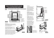
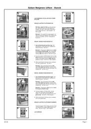
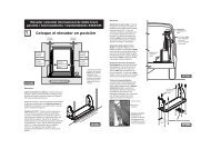
When in the stowed (folded)<br />
position, the ramp assembly can<br />
be manually rotated out of the<br />
slide door opening. This feature<br />
allows passive (non-wheelchair)<br />
access to the passenger side<br />
slide door opening when desired.<br />
The ramp assembly can also be<br />
manually removed (details on<br />
following page).<br />
The ramp assembly pivots<br />
(rotates) on two axles (top and<br />
bottom) when the ramp latch is<br />
disengaged. The front of the<br />
ramp is secured to the vehicle<br />
floor with a cable activated<br />
spring-loaded latch.<br />
The ramp latch is located at floor<br />
level at the front of the ramp (see<br />
Photo B). The latch is activated<br />
by a release cable. The release<br />
CAUTION<br />
• Open door fully<br />
before rotating ramp.<br />
• Do not fold or unfold<br />
ramp when ramp<br />
latch is disengaged<br />
or ramp is in passive<br />
position (rotated out<br />
of vehicle).<br />
Failure to follow these<br />
rules may result in<br />
personal injury and/or<br />
property damage.<br />
Passive (Non-Wheelchair) Access Instructions<br />
For Passive (Non-Wheelchair) Access:<br />
cable is routed upward through<br />
the front slide door post interior<br />
panel. The cable is equipped<br />
with a knob for use as a latch<br />
release handle (see Photo A).<br />
The knob is located adjacent to<br />
the front top corner of the ramp<br />
(when ramp is in stowed position).<br />
Open the door fully before<br />
manually rotating ramp. Release<br />
the OPEN switch as soon<br />
the door is fully open.<br />
1. Press the OPEN switch or turn the Outside Key<br />
Entry key clockwise until the door opens fully.<br />
Release switch or key (see Delay Feature above).<br />
2. Pull cable knob UP fully to unlatch ramp. See<br />
Photo A.<br />
3. Manually rotate ramp OUT. See Photo C. Secure<br />
and support the ramp during passenger<br />
access. Caution: Do not force ramp open. Do<br />
not attempt to activate the power ramp when in<br />
the passive position (rotated out of vehicle).<br />
Delay Feature: After the door is<br />
fully open, a minimum two second<br />
delay will occur before the ramp<br />
starts to unfold. The delay allows<br />
the operator adequate time to<br />
release the OPEN switch (or<br />
outside key entry), once the door<br />
is open - preventing the automatic<br />
ramp from unfolding.<br />
Do not attempt to fold or unfold<br />
the ramp when the latch is<br />
disengaged or the ramp is in<br />
the passive position (rotated out<br />
of vehicle).<br />
The instructions provided below<br />
outline the step-by-step procedures<br />
required to manually rotate<br />
the ramp. These instructions also<br />
appear on Passive (Non-Wheelchair)<br />
Access Instructions decal<br />
#18515 (posted on the front slide<br />
door post interior wall panel<br />
adjacent to the release knob).<br />
Release Knob<br />
Ramp<br />
Ramp Latch<br />
To Store Ramp and Close Door:<br />
1. Manually rotate ramp IN fully to latch ramp.<br />
2. Press the CLOSE switch or turn the Outside Key<br />
Entry key counterclockwise until the door closes<br />
fully.<br />
A<br />
B<br />
C<br />
Page 19<br />
Operation
Operation<br />
When in the stowed (folded)<br />
position, the ramp and motor<br />
assembly can be manually<br />
removed from the vehicle. Open<br />
the door fully before manually<br />
removing the ramp. Release<br />
the OPEN switch (or outside<br />
key entry), as soon as the door<br />
is fully open.<br />
The front of the ramp is secured<br />
to the vehicle floor with the cable<br />
activated Passive Access latch.<br />
The latch must be disengaged in<br />
order to remove the ramp. See<br />
previous page for Passive<br />
Access details and photos.<br />
Page 20<br />
Ramp Removal Instructions<br />
Jumper (loose)<br />
Ramp<br />
Motor<br />
9-Circuit Sockets<br />
D<br />
Ramp Wiring Harness<br />
Connected<br />
The rear of the ramp and motor assembly is secured to the rear<br />
door post with a hairpin cotter. See Photo F. The hairpin cotter<br />
must be removed in order to remove the ramp.<br />
CAUTION<br />
Disconnect ramp<br />
motor wiring harness<br />
before removing ramp.<br />
Failure to do so will<br />
result in damage.<br />
Disconnect the ramp motor<br />
harness before removing the<br />
ramp. Failure to do so will result<br />
in damage. The power ramp motor<br />
electrical wiring harness is located<br />
within the interior wall panel by the<br />
ramp motor as shown in Photos D<br />
and E. Depress the locking tabs to<br />
disconnect the 9-circuit sockets.<br />
Note: A jumper wire assembly is attached to the main wiring<br />
harness. Install the jumper wire 9-circuit socket in the main<br />
harness 9-circuit socket that the ramp motor harness was connected<br />
to. See Photos D and E. Connecting the jumper wire<br />
provides power to the door operator when the ramp is removed.<br />
The instructions provided below outline the step-by-step procedures<br />
required to manually remove the ramp.<br />
Ramp Removal Instructions:<br />
1. Press the OPEN switch or turn the Outside Key<br />
Entry key clockwise until the door opens fully.<br />
Release switch or key.<br />
2. Disconnect the ramp electrical wiring harness.<br />
See Photo D. Note: It may be necessary to<br />
partially rotate the ramp to access the wiring<br />
harness and jumper wire.<br />
3. Connect the jumper wire to the main electrical<br />
harness. See Photo E.<br />
Jumper (installed)<br />
Hairpin Cotter<br />
Main Harness<br />
Socket<br />
Ramp Wiring Harness<br />
Disconnected<br />
Note: Ramp rotated for clear view<br />
of wiring harness and jumper wire<br />
in Photos D and E.<br />
Ramp Motor Assembly<br />
G<br />
Flat washer positions on floor rotation<br />
axle.<br />
E<br />
F
Ramp Removal Instructions (continued):<br />
3. Remove the hairpin cotter from the top ramp pivot<br />
axle. See Photo F on previous page.<br />
Note: Keep the hairpin cotter when removing the<br />
ramp. The hairpin cotter must be repositioned<br />
when reinstalling the ramp assembly.<br />
4. Pull release knob UP fully to unlatch ramp. See<br />
Photo A on page 19.<br />
5. Grip both sides of the ramp assembly and lift up.<br />
Manually remove ramp. See Photo G on previous<br />
page. Use good body mechanics when<br />
WARNING<br />
• Clear ramp path<br />
before performing<br />
manual unfold<br />
procedures. Ramp<br />
will free-fall.<br />
• Be certain door is<br />
fully open.<br />
• Keep clear of<br />
moving parts.<br />
Failure to follow<br />
these rules may<br />
result in serious<br />
bodily injury and/or<br />
property damage.<br />
Notes: The vehicle<br />
transmission must be<br />
engaged in Park “P” and<br />
the parking brake must be<br />
engaged before performing<br />
all manual operation<br />
procedures.<br />
The MANUAL/AUTO<br />
switch must be in the<br />
MANUAL position before<br />
performing manual ramp<br />
operation procedures.<br />
Ramp Removal Instructions<br />
removing the ramp. Keep your back straight and<br />
bend your knees when lifting the ramp.<br />
Note: Keep the flat washer positioned on the<br />
floor rotation axle when removing the ramp. The<br />
washer must be repositioned when reinstalling<br />
the ramp assembly. See Photo G.<br />
Reverse procedures to install ramp.<br />
Note: Be certain the flat washer and hairpin<br />
cotter are repositioned when reinstalling the ramp<br />
assembly.<br />
Door and Ramp Manual Operating Instructions<br />
If you experience power or equipment<br />
failure, refer to the step-by-step<br />
instructions on the following page to<br />
manually operate the slide door and<br />
ramp. Manual operation instructions<br />
also appear on Manual Operation<br />
instructions decal #52212 (posted on<br />
the power ramp motor housing).<br />
Note: It is recommended to have an<br />
assistant aid in performing manual<br />
operating procedures. Many wheelchair<br />
passengers will not be able to<br />
perform manual operating procedures.<br />
An assistant may be required.<br />
Use good body mechanics when<br />
A red manual door release<br />
handle is located rear of the<br />
power ramp as shown. In the<br />
event you experience power<br />
or equipment failure, the slide<br />
door can be opened manually.<br />
Pull red manual door release<br />
handle UP fully to release<br />
(disengage) the door operator.<br />
Push the release handle<br />
DOWN fully to re-engage the<br />
door operator.<br />
WARNING<br />
Keep clear of<br />
area in which<br />
ramp operates.<br />
52205<br />
performing manual ramp operating<br />
procedures. Keep your back<br />
straight and bend your knees when<br />
folding (lifting) the ramp.<br />
Operate door and/or ramp<br />
manually ONLY if either cannot<br />
be operated electrically.<br />
MANUAL/AUTO Switch Release Handle<br />
Page 21<br />
Operation
Operation<br />
Page 22<br />
WARNING<br />
• Clear ramp path<br />
before performing<br />
manual unfold<br />
procedures. Ramp<br />
will free-fall.<br />
• Be certain door is<br />
fully open.<br />
• Keep clear of<br />
moving parts.<br />
Failure to follow<br />
these rules may<br />
result in serious<br />
bodily injury and/or<br />
property damage.<br />
TO UNFOLD RAMP:<br />
Door and Ramp Manual Operating Instructions<br />
1. Clear the ramp path! Note: The ramp path must be clear.<br />
The ramp will free-fall when pushed out. An assistant should<br />
carefully unfold and lower the ramp to the ground from outside<br />
the vehicle if possible (Photo C).<br />
2. Push top of ramp out (if an assistant is not available only). See<br />
Photo B.<br />
TO FOLD RAMP:<br />
Carefully lift and fold the ramp fully (to stowed position). See<br />
Photo C. Note: Remember to use good body mechanics. Assistants<br />
should keep their back straight and bend knees when lifting.<br />
Lift from the outboard end of the ramp. Keep body parts and<br />
obstructions clear of the area in which the ramp operates.<br />
TO CLOSE DOOR<br />
(To Re-engage Door Operator):<br />
Note: The MANUAL/AUTO<br />
switch must be pressed to the<br />
AUTO (down) position before<br />
performing electric procedures.<br />
Read page 21 before proceeding!<br />
Note: Engage vehicle transmission<br />
in Park,engage vehicle parking<br />
brake and press MANUAL/AUTO<br />
switch to the MANUAL position<br />
before performing manual ramp<br />
operation procedures.<br />
TO OPEN DOOR<br />
(To Disengage Door Operator):<br />
1. Pull red manual door release<br />
handle UP fully. See Photo A.<br />
2. Manually open door fully.<br />
3. Push red manual door release<br />
handle DOWN fully to secure door.<br />
See Photo A. Note: It may be<br />
necessary to push the door to the<br />
rear while simultaneously securing<br />
the door with the handle.<br />
1. Pull red manual door release handle UP fully. See Photo A.<br />
2. Carefully manually close door fully. Note: Be certain the power<br />
door gear rack enters (aligns with) the access hole located in the<br />
door opening front door post when closing the door (Photo D).<br />
3. Push red manual door release handle DOWN fully to secure<br />
door. See Photo A. Note: It may be necessary for an assistant<br />
to close the door tight from outside the vehicle while engaging<br />
the release handle.<br />
The power ramp cannot be<br />
activated unless the MANUAL/<br />
AUTO switch is in the AUTO<br />
(down) position.<br />
Access Hole<br />
Gear Rack<br />
UNFOLD<br />
FOLD<br />
ENGAGE<br />
B<br />
Push ramp out if an assistant is not<br />
available ONLY!<br />
RELEASE<br />
A<br />
C<br />
D
WARNING<br />
Driving an Entervan<br />
in the kneeled (lowered)<br />
position may<br />
result in serious<br />
bodily injury and/or<br />
property damage.<br />
Kneel Actuator Manual Release Instructions<br />
Mechanical Kneeling Override: A manual release<br />
feature is built into the electric actuator-powered<br />
electromechanical kneel system. In the event that<br />
the Entervan is in the kneeled position and you<br />
experience power or equipment failure, the Kneel<br />
Actuator Manual Release feature allows the rear of<br />
the vehicle to raise to the normal position.<br />
Manual Release Lever: A red-handled kneel<br />
actuator manual release lever protrudes out of the<br />
driver side interior wall panel rear of the sliding door.<br />
A detent pin is inserted in the release handle. Refer<br />
to the instructions provided on the following page<br />
and appearing on Kneel Actuator Manual Release<br />
Instructions decal #52215 to manually release<br />
(override) the kneel actuator.<br />
In the event that the<br />
Entervan is in the<br />
kneeled position and<br />
you experience<br />
power or equipment<br />
failure, do not<br />
continue to drive<br />
the Entervan with<br />
the rear of the<br />
vehicle in the<br />
lowered position.<br />
Attempting to drive the Entervan with the rear of the<br />
vehicle in the lowered position will result in an<br />
extremely rough and unstable ride, and could<br />
possibly result in injury and/or vehicle damage.<br />
The vehicle would ride as if it did not have any rear<br />
suspension. In the event of a kneel system<br />
failure, have the kneel system repaired immediately.<br />
Contact your dealer or call 1-800-THE LIFT.<br />
One of our national service representatives will<br />
direct you to an authorized service repairman who<br />
will inspect your Entervan.<br />
Use Kneel Actuator Manual Release ONLY<br />
if the vehicle will not raise electrically.<br />
Kneel Actuator<br />
Black MANUAL/AUTO Switch<br />
Press the black MANUAL/AUTO switch to<br />
the MANUAL (up) position before performing<br />
Kneel Actuator Manual Release Procedures.<br />
Press the black MANUAL/AUTO switch to<br />
the AUTO (down) position before performing<br />
Automatic Power Kneeling Operations.<br />
The kneeling system is powered by an electric<br />
actuator that compresses the rear suspension when<br />
the actuator is retracted. The electric brake built<br />
into the actuator is mechanically released when the<br />
red-handled kneel actuator manual release lever is<br />
pulled. A cable is attached to the release handle<br />
which mechanically releases the actuator brake.<br />
When the actuator brake is released, the suspension<br />
leaf springs override the actuator, resulting in<br />
the rear of the vehicle raising.<br />
The kneel actuator<br />
MANUAL/AUTO<br />
switch must be<br />
pressed to the<br />
MANUAL (up)<br />
position in order to<br />
manually release the<br />
actuator. If the switch<br />
is not in the MANUAL<br />
(up) position, there<br />
will be too much<br />
physical resistance to<br />
accomplish the<br />
manual release.<br />
Kneel Actuator Manual Release<br />
Instructions Decal #52215<br />
KNEEL ACTUATOR<br />
MANUAL RELEASE<br />
Use only if vehicle will not<br />
raise electrically.<br />
1. Press MANUAL/AUTO switch<br />
to MANUAL position.<br />
2. Pull detent pin.<br />
3. Pull red handled lever fully.<br />
4. Insert detent pin in lever hole.<br />
Note: Pull detent pin, return lever<br />
to original position and press<br />
MANUAL/AUTO switch to AUTO<br />
position before performing electric<br />
procedures.<br />
52215<br />
CAUTION<br />
Press kneel actuator<br />
MANUAL/AUTO<br />
switch to MANUAL<br />
(up) position before<br />
pulling the kneel<br />
actuator manual<br />
release lever. Failure<br />
to do so may result in<br />
property damage.<br />
Do not attempt to manually release the kneel<br />
actuator if you have not experienced power or<br />
equipment failure. Damage to the manual<br />
release system could occur.<br />
Note: Press the MANUAL/AUTO switch to AUTO<br />
(down) position before performing electrical<br />
procedures. The electric actuator-powered electromechanical<br />
Kneel system cannot be activated if the<br />
Kneel Actuator MANUAL/AUTO switch is not in the<br />
AUTO (down) position.<br />
MANUAL<br />
AUTO<br />
Detent<br />
Pin<br />
Kneel<br />
Actuator<br />
Release<br />
Lever<br />
Page 23<br />
Operation
Operation<br />
Page 24<br />
Kneel Actuator Manual Release Instructions<br />
In the event that the Entervan is in the kneeled<br />
position and you experience power or equipment<br />
failure, refer to the instructions provided below and<br />
on Kneel Actuator Manual Release Instructions<br />
CAUTION<br />
Press kneel actuator<br />
MANUAL/AUTO<br />
switch to MANUAL<br />
(up) position before<br />
pulling the kneel<br />
actuator manual<br />
release lever. Failure<br />
to do so may result in<br />
property damage.<br />
Kneel Actuator<br />
Manual Release Instructions<br />
Use the Kneel Manual Release ONLY if<br />
the vehicle will not raise electrically.<br />
Read page 23 before performing<br />
this procedure!<br />
1. Press Kneel Actuator MANUAL/AUTO<br />
switch to MANUAL (up) position. See<br />
Photo A.<br />
2. Pull to remove the ringed-detent pin<br />
inserted in the release lever. See<br />
Photo B.<br />
3. Pull the red-handled lever fully<br />
rearward. See Photo C.<br />
4. Insert the detent pin in the hole<br />
located in the lever. See Photo C.<br />
Note: Pull detent pin, return lever to<br />
original position, insert detent pin<br />
and press the Kneel MANUAL/AUTO<br />
switch to AUTO (down) position<br />
before performing electrical<br />
procedures.<br />
decal #52215 to<br />
manually release<br />
(override) the kneel<br />
actuator (raise the<br />
rear of the vehicle to<br />
the normal position).<br />
Kneel Actuator<br />
MANUAL/AUTO<br />
Switch<br />
Do not attempt to<br />
manually release the<br />
kneel actuator if you<br />
have not experienced<br />
power or equipment<br />
failure. Damage to<br />
the manual release<br />
system could occur.<br />
See previous page for<br />
further details.<br />
Detent Pin Kneel Actuator<br />
KNEEL ACTUATOR<br />
MANUAL RELEASE Release Lever<br />
1<br />
MANUAL<br />
AUTO<br />
Use only if vehicle will not<br />
raise electrically.<br />
1. Press MANUAL/AUTO switch<br />
to MANUAL position.<br />
2. Pull detent pin.<br />
3. Pull red handled lever fully.<br />
4. Insert detent pin in lever hole.<br />
Note: Pull detent pin, return lever<br />
to original position and press<br />
MANUAL/AUTO switch to AUTO<br />
position before performing electric<br />
procedures.<br />
52215<br />
Kneel Actuator Release Lever in Normal Position.<br />
2<br />
4<br />
WARNING<br />
Driving an Entervan<br />
in the kneeled (lowered)<br />
position may<br />
result in serious<br />
bodily injury and/or<br />
property damage.<br />
3<br />
A<br />
B<br />
C
A<br />
C<br />
B<br />
Wheelchair and Occupant Restraint<br />
Wheelchair passengers<br />
shown depict the<br />
available wheelchair<br />
seating positions.<br />
Wheelchair capacity at<br />
Mid-Point (Position C)<br />
may have limitations<br />
based on the physical<br />
dimensions of specific<br />
wheelchairs.<br />
Horizontal<br />
“A” Track<br />
Horizontal<br />
“A” Track<br />
Note: See page 3 for photos of horizontal “A” track<br />
in the Front Lowered Floor Area (Position B) and<br />
the Mid-Point Lowered Floor Area (Position C).<br />
Forward-Facing Wheelchair and Occupant Belt/Track System<br />
One Forward-Facing Wheelchair and Occupant Belt/<br />
Track System is supplied with the Entervan II. This<br />
system is provided for the restraint of one wheelchair<br />
and occupant only. Note: The Entervan can accommodate<br />
more than one wheelchair passenger (as<br />
shown above). Additional Forward-Facing Tie-Down<br />
Belt Kits must be purchased for restraint of each<br />
additional wheelchair passenger. Note: Wheelchair<br />
passengers shown depict the available seating positions.<br />
Wheelchair capacity at Mid-Point (Position C)<br />
may have limitations based on the physical dimensions<br />
of specific wheelchairs.<br />
The Forward-Facing Wheelchair and Occupant Belt/<br />
Track System consists of:<br />
1. “A” track mounted in the vehicle (three locations<br />
shown above) to be used in conjunction with the<br />
Forward-Facing Wheelchair and Occupant belts<br />
supplied.<br />
The Entervan II offers the following options for<br />
placement and securement of wheelchair<br />
passengers.<br />
Quick-Release Driver Seat: This seat<br />
(Position A) can be removed and adaptive<br />
driving systems custom tailored for the driving<br />
wheelchair occupant can be purchased from<br />
and installed by your local dealer. See pages<br />
30 and 31 for seat removal and installation<br />
instructions.<br />
Quick-Release Front Passenger Seat with<br />
Floor Track for Wheelchair and Occupant<br />
Securement: This seat (Position B) can be<br />
removed and the seat location can be utililized<br />
by a wheelchair occupant. The wheelchair<br />
occupant must be secured using the Forward-<br />
Facing Wheelchair and Occupant Belt/Track<br />
System provided (detailed below).<br />
Floor Track for Wheelchair and Occupant<br />
Securement in Mid-Point Lowered Floor<br />
Area: The Mid-Point lowered floor area<br />
(Position C) can be utililized by wheelchair<br />
occupant(s). The wheelchair occupant must<br />
be secured using the Forward-Facing Wheelchair<br />
and Occupant Belt/Track System<br />
provided (detailed below).<br />
One Forward-Facing Wheelchair and<br />
Occupant Belt/Track System (detailed<br />
below) is supplied with the Entervan II. This<br />
system is provided for the restraint of one<br />
wheelchair and occupant only.<br />
2. Forward-Facing Wheelchair and Occupant Belt Kit<br />
#51140A — consisting of:<br />
• Two adjustable over-center buckle belts for<br />
securement of the rear of the wheelchair.<br />
• Two adjustable cam buckle belts for securement of<br />
the front of the wheelchair.<br />
• One adjustable lap belt equipped with one “E” clip<br />
which installs in the vehicle-mounted “A” track and<br />
one female buckle receptacle. This lap belt is<br />
used in conjunction with the vehicle factoryequipped<br />
(OEM) upper torso shoulder harness.<br />
Refer to the following guidelines, illustrations and the<br />
Belt Attachment Instructions on pages 26 through 29<br />
for proper use of the Forward-Facing Wheelchair and<br />
Occupant Belt/Track System.<br />
Page 25<br />
Operation
Operation<br />
No product developed to<br />
date can guarantee<br />
successful securement<br />
of the wheelchair, even<br />
at low speeds, in the<br />
event of an accident.<br />
The <strong>Braun</strong> Wheelchair<br />
and Occupant Belt/Track<br />
System does meet the<br />
most widely referenced<br />
Federal Motor Vehicle<br />
Safety Standards used<br />
for contemporary<br />
restraint equipment.<br />
However, this equipment<br />
does not ensure stability<br />
of the wheelchair in the<br />
event of an accident at<br />
any speed.<br />
Page 26<br />
Wheelchair and Occupant Restraint<br />
WARNING WARNING WARNING<br />
Read and become<br />
familiar with all Forward-<br />
Facing Wheelchair and<br />
Occupant Belt/Track<br />
System instructions as<br />
specified in this manual<br />
prior to installation or<br />
operation procedures. If<br />
the instructions are not<br />
fully understood,<br />
contact The <strong>Braun</strong><br />
<strong>Corporation</strong> immediately.<br />
Failure to do so<br />
may result in property<br />
damage, serious bodily<br />
injury and/or death.<br />
Note: This information<br />
is not all inclusive and<br />
will not cover every<br />
wheelchair installation.<br />
Each wheelchair must<br />
be carefully and<br />
individually fitted,<br />
reviewed and tested to<br />
provide maximum<br />
comfort and protection<br />
for the end user.<br />
Forward-Facing Wheelchair and Occupant Belt/Track System Instructions<br />
Refer to the following guidelines, illustrations and<br />
instructions for proper use of the Forward-Facing<br />
Wheelchair and Occupant Belt/Track System.<br />
Wheelchair Passenger Securement<br />
One adjustable lap belt equipped with one “E” clip<br />
(keeper) which installs in the vehicle-mounted “A” track<br />
and one female buckle receptacle is provided to be<br />
used in conjunction with the existing vehicle OEM<br />
factory-equipped upper torso shoulder harness, for<br />
securement of the wheelchair occupant. Refer to the<br />
illustrations on page 27.<br />
Lap Belt Positioning and Attachments<br />
Refer to the illustrations on page 27.<br />
A. Position of the lap belt buckle, after adjustment, is to<br />
be located near hip position. The belt is to be worn low<br />
and snugly. Adjustment of the lap belt is to be made at<br />
adjuster buckle behind the chair.<br />
B. The lap belt must be used in conjunction with the<br />
vehicle factory-equipped upper torso shoulder harness.<br />
The latch plate side of belt must be opposite shoulder<br />
harness to properly extend shoulder harness across<br />
occupant. The lap belt end fitting (keeper) must be<br />
attached to vehicle-mounted “A” track as outlined in<br />
Wheelchair and Occupant Belt/Track Attachment<br />
When using wheelchair<br />
restraints not supplied<br />
with the Entervan, read<br />
and become familiar<br />
with all installation and<br />
operation instructions<br />
supplied with your<br />
particular wheelchair<br />
restraint system prior to<br />
installation or operation<br />
procedures. If the<br />
instructions are not fully<br />
understood, contact the<br />
manufacturer immediately.<br />
Failure to do so<br />
may result in property<br />
damage, serious bodily<br />
injury and/or death.<br />
Instructions on page 28, (Steps 2 and 3).<br />
C. Proper position of lap belt track attachments is with<br />
release keeper toward the rear away from wheelchair.<br />
Wheelchair Securement<br />
Two adjustable over-center buckle belts are provided<br />
for securement of the rear of the wheelchair. Two<br />
adjustable cam buckle belts are provided for<br />
securement of the front of the wheelchair. Refer to the<br />
illustrations on page 27 and the Belt Attachment<br />
Instructions on pages 28 and 29 .<br />
Belt Maintenance<br />
Inspect seat belt assemblies frequently during time in<br />
service to evaluate system for belt wear. Any defects<br />
such as belt cut, fraying or malfunctioning call for<br />
replacement of the entire system including belt, buckle<br />
and hardware.<br />
Any seat belt system exposed to environmental<br />
conditions or climates such as dirt, mud, oil, sand,<br />
cement, and grease will severely reduce the life of the<br />
system. Extreme care must be taken in the inspection<br />
of a system exposed to these conditions. The replacement<br />
of the system must be a top priority to ensure<br />
efficient functioning of the system and enhance the<br />
safety to the end user.
Keeper<br />
(“E” Clip)<br />
Horizontal<br />
“A” Track<br />
Keeper<br />
(“E” Clip)<br />
Note: Passenger side<br />
mid-point position shown.<br />
Driver side mid point<br />
securement is a mirrored<br />
image. Attachment<br />
procedures are identical.<br />
Keeper (“E” Clip)<br />
attachment details<br />
are provided on page<br />
28 (Steps 2 and 3).<br />
Keeper<br />
(“E” Clip)<br />
Wheelchair and Occupant Restraint<br />
Adjustable Cam<br />
Buckle Belt<br />
Adjustable Cam<br />
Buckle Belt<br />
Adjustable Cam<br />
Buckle Belt<br />
Existing Vehicle Factory<br />
OEM Installed Upper<br />
Torso Shoulder Harness<br />
Over-center<br />
Buckle Belt<br />
Over-center<br />
Buckle Belt<br />
Over-center<br />
Buckle Belt<br />
Adjustable<br />
Lap Belt<br />
Existing Vehicle OEM<br />
Factory-Equipped Upper<br />
Torso Shoulder Harness<br />
Adjustable<br />
Lap Belt<br />
Horizontal<br />
“A” Track<br />
Horizontal<br />
“A” Track<br />
Horizontal “A” Track<br />
on Floor<br />
Page 27<br />
Operation
Operation<br />
Strap Angle Positioning:<br />
The load angle should not be<br />
less than 30° or more than 60°<br />
from vertical in a plane along<br />
the fitting width as shown.<br />
3<br />
4<br />
6<br />
Track Center Line<br />
Page 28<br />
Load<br />
Angle<br />
Wheelchair and Occupant Restraint<br />
Forward-Facing Wheelchair and Occupant Belt/Track System Instructions<br />
Front Cam Buckle Strap<br />
Attachments<br />
Read all <strong>warning</strong>s posted on<br />
page on page 26!<br />
1. Position and install the strap’s<br />
track fitting three inches to eight<br />
inches outside the front wheel<br />
with the keeper away from<br />
wheelchair.<br />
2. To install the track fitting,<br />
depress the keeper and insert<br />
the fitting (keeper end first) into<br />
the track as shown.<br />
3. Drop back end of fitting into<br />
track, and release keeper to lock<br />
as shown. Pull on fitting to<br />
ensure that it is locked in track.<br />
To remove, simply reverse the<br />
procedure.<br />
4. Loop the other end of the strap<br />
around the front of the wheelchair<br />
frame at a structurally<br />
secure location and attach the<br />
snap hook into the round ring as<br />
shown. Be careful to keep the<br />
strap away from sharp edges or<br />
corners.<br />
5. Pull the tensioning strap on the<br />
cam buckle until tight. Repeat<br />
the four steps for the other front<br />
strap, making certain the<br />
wheelchair is positioned perpendicular<br />
to the floor track.<br />
6. Velcro* is provided to attach<br />
loose strap ends.<br />
7. To release the tension on the<br />
strap, press the buckle cam as<br />
shown.<br />
*Velcro is a registered trademark of<br />
Velcro USA, Inc.<br />
continued<br />
3" to 8"<br />
1<br />
2<br />
5<br />
7
Read all <strong>warning</strong>s posted on page 26!<br />
Wheelchair and Occupant Restraint<br />
Rear Over-Center Strap<br />
Attachments<br />
1. Position and install the strap’s<br />
track fitting below and just to the<br />
inside of the rear wheel as<br />
shown. Pull on fitting to ensure<br />
that it is locked in track. Note:<br />
See steps 2 and 3 on the<br />
opposite page for further track<br />
fitting (keeper) details.<br />
2. Wrap the other end of the strap<br />
around the back of the wheelchair<br />
frame at a structurally<br />
secure location and attach the<br />
snap hook into the round ring.<br />
Be careful to keep the strap<br />
away from sharp edges or<br />
corners.<br />
3. Pull the tensioning strap until<br />
tight. While maintaining tension,<br />
lift handle, close and lock<br />
handle. Pull on buckle handle to<br />
ensure that it is locked.<br />
4. To release over-center buckle,<br />
simply pull down tensioning strap<br />
towards floor as shown.<br />
Chrysler Easy-Out Roller Rear Bench Seat<br />
The 3-Passenger Rear Bench Seat (standard<br />
Entervan feature) is equipped with Chrysler Easy-<br />
Out Rollers . Refer to your Chrysler owner’s<br />
manual for removal and installation instructions for<br />
this seat.<br />
WARNING<br />
Install, remove and<br />
operate Chrysler<br />
Easy-Out seats as<br />
detailed in Chrysler<br />
owner's manual.<br />
Failure to do so may<br />
result in serious<br />
bodily injury and/or<br />
property damage.<br />
Page 29<br />
Operation
Operation<br />
Seat attachments<br />
must be fully latched<br />
in floor supports<br />
before occupying<br />
seats or operating<br />
vehicle. Failure to<br />
do so will result in<br />
serious bodily injury.<br />
Front seat removal and<br />
installation procedures are<br />
identical for driver and passenger<br />
seat (driver seat photos shown).<br />
Page 30<br />
Quick-Release Front Seats<br />
Seat Securement Devices:<br />
The quick-release front seats are<br />
equipped with mechanical seat<br />
base attachments that attach to<br />
recessed floor strikers (supports).<br />
Two release handles are located<br />
at the rear of the seat base.<br />
Squeezing the handles and<br />
rotating the handles downward<br />
Quick-Release Front Seats<br />
Front Seat Removal<br />
disengages the attachments and<br />
deploys the wheels. Squeezing<br />
the handles and rotating the<br />
handles upward engages the<br />
attachments.<br />
A lock indicator button pops up<br />
when the seat is unlocked. The<br />
indicator button returns into the<br />
handle when the attachment<br />
mechanism is in the fully-engaged<br />
position (seat base attachments<br />
are fully-engaged with floor<br />
strikers) and in the fully-disengaged<br />
position (seat base attachments<br />
are fully-disengaged from<br />
floor strikers and wheels are<br />
deployed).<br />
A 1. Disconnect the electrical harness<br />
sockets (carefully pull<br />
sockets apart).<br />
B<br />
Disconnect sockets.<br />
2. Squeeze the release handles<br />
located at the rear of the seat<br />
bases and rotate downward.<br />
Rotate the handles down fully<br />
until the handles reach the<br />
locked (horizontal) position and Fully-Engaged Seat Attachments<br />
Lock Indicator Button UP<br />
(Mid-Point of Handle Rotation).<br />
the indicator buttons return into<br />
the handles (photos B-D).<br />
Fully-Disengaged Seat Attachments<br />
(Wheels Deployed)<br />
C Note: A lock indicator button<br />
pops up when the seat is<br />
unlocked (mid-point of handle<br />
rotation). The indicator buttons<br />
return into the handles when the<br />
handles are rotated fully down<br />
(seat base attachments are fullydisengaged<br />
from floor strikers<br />
and wheels are deployed).<br />
D<br />
DISENGAGE<br />
WARNING<br />
Release Handles<br />
Wheels Recessed Floor Supports<br />
Driver's Seat Base Foot Rest<br />
Driver's Seat Electrical Harness<br />
DISENGAGE<br />
DISENGAGE
CAUTION<br />
Do not contact the<br />
ramp when reclining<br />
or moving a passenger<br />
seat rearward.<br />
Doing so may result<br />
in property damage.<br />
Quick-Release Front Seats<br />
Front Seat Removal continued<br />
Connect sockets.<br />
3. Tip seat slightly backwards<br />
and roll seat base out of<br />
vehicle.<br />
Front Seat Installation<br />
1. Roll seat base into position<br />
(aligning the seat base<br />
attachments with the recessed<br />
floor strikers).<br />
2. Squeeze the release handles<br />
located at the rear of the<br />
seat bases and rotate<br />
upward to latch the seat<br />
base attachments with the<br />
recessed floor strikers<br />
(receptacles). Rotate the<br />
handles up and fully forward<br />
until the handles reach the<br />
locked position and the<br />
indicator buttons return into<br />
the handles. See photos F,<br />
G and H.<br />
Note: Be certain all seat<br />
base attachments are fully<br />
latched. Read <strong>warning</strong> on<br />
opposite page!<br />
3. Connect (plug) the electrical<br />
harness sockets.<br />
Fully-Disengaged Seat Attachments<br />
(Wheels Deployed)<br />
ENGAGE<br />
ENGAGE<br />
Lock Indicator Button UP<br />
(Mid-Point of Handle Rotation).<br />
ENGAGE<br />
Fully-Engaged Seat Attachments<br />
F<br />
G<br />
H<br />
Page 31<br />
Operation
Operation<br />
Spare Tire and Jack Location: Due to the modifications*<br />
made to the Chrysler OEM (factory) chassis<br />
during the Entervan conversion process, the Entervan<br />
spare tire and jack are relocated. The spare tire<br />
is mounted to the spare tire mount and storage<br />
cabinet located inside the rear of the Entervan, not<br />
in the location outlined in the Chrysler-supplied<br />
owner’s manual. The jack and jack handle are<br />
stored in the spare tire mount and storage cabinet.<br />
Jacking and tire changing procedures have not been<br />
affected by the conversion. Detailed tire changing<br />
instructions are provided in the Chrysler-supplied<br />
owner’s manual. Refer to the Chrysler-supplied<br />
manual for tire changing instructions and safety<br />
precautions, as well as instructions regarding<br />
other roadside emergencies.<br />
Altered Vehicle decal #21422 (stapled below) is<br />
supplied to notify anyone raising or changing a tire<br />
on an Entervan that the spare tire and jack have<br />
been relocated. Affix decal #21422 to the appropriate<br />
page in the Chrysler-supplied owner’s manual<br />
Page 32<br />
Storage Cabinet Handle<br />
Spare Tire Mount and Storage Cabinet<br />
The storage cabinet provides<br />
storage for the wheelchair and<br />
occupant restraint belts. The<br />
cabinet can also be used for<br />
storage of roadside emergency<br />
equipment.<br />
Lift and rotate the handle counterclockwise<br />
to open the cabinet.<br />
Rotate the handle clockwise and<br />
push in to latch the handle.<br />
Wheelchair and<br />
Occupant Belts<br />
Tire Changing<br />
Tire Cover Spare Tire Mount and<br />
Storage Cabinet<br />
where the Tire Changing Instructions begin. In the<br />
event that someone attempting to raise the vehicle<br />
does not refer to this manual, Altered Vehicle decal<br />
#21422 will direct the person to the spare tire and<br />
jack storage location.<br />
Decal #21422<br />
* This vehicle was altered by The<br />
<strong>Braun</strong> <strong>Corporation</strong> and as altered<br />
it conforms to all Federal Motor<br />
Vehicle Safety Standards affected<br />
by the alteration in effect at the<br />
date of manufacture.
Spare Tire Access<br />
1. Remove the tire cover.<br />
2. Loosen and remove the retaining nut (turn<br />
counterclockwise). Remove the spare tire.<br />
Tire Changing<br />
Jack Location and Access<br />
1. Remove spare tire as detailed at left.<br />
2. Loosen and remove the jack storage threaded<br />
retainer stud (turn counterclockwise). Remove<br />
the jack and jack handle.<br />
Retaining Nut Jack Storage Threaded Retainer Stud<br />
Tire Changing Instructions<br />
WARNING<br />
Follow all jacking<br />
and tire changing<br />
instructions and<br />
safety precautions<br />
in the Chryslersupplied<br />
owner's<br />
manual when changing<br />
a flat tire or<br />
raising the vehicle.<br />
Failure to do so may<br />
result in serious<br />
bodily injury and/or<br />
property damage.<br />
1. Press the dashmounted<br />
red<br />
KNEEL switch to<br />
the NO (down)<br />
position. If the rear<br />
of the vehicle is in<br />
the kneeled position,<br />
the rear of the<br />
vehicle will raise<br />
automatically.<br />
Note: If you have<br />
experienced power<br />
or equipment failure<br />
and the vehicle is in<br />
the kneeled position,<br />
refer to the<br />
Kneel Actuator<br />
Manual Release Instructions on pages 23 and 24<br />
of this manual to raise the vehicle. Kneel Actuator<br />
Manual Release Instructions decal #52215 is<br />
posted on the driver side interior wall panel rear<br />
of the sliding door above the red-handled manual<br />
release lever assembly. This decal provides<br />
instructions for overriding the kneel system.<br />
2. Refer to the Chrysler factory-supplied manual<br />
for tire changing instructions.<br />
3. Store and Secure Jack and Tire: Replace the<br />
jack and jack handle in the spare tire mount and<br />
storage cabinet and resecure. Secure the flat tire<br />
to the spare tire mount and storage cabinet.<br />
Compact Spare Tire: The compact spare tire<br />
and wheel assembly (if so equipped), is for<br />
emergency use only (not for continuous use).<br />
The compact tire should only be used for the<br />
minimum length of time (mileage) required to get<br />
to a tire service center. Have the proper (original<br />
- full size) tire repaired or replaced immediately.<br />
Repair or replace the spare tire if worn or damaged.<br />
Page 33<br />
Operation
Maintenance<br />
Maintenance and<br />
lubrication procedures<br />
should be<br />
performed as specified<br />
by authorized<br />
service personnel.<br />
Failure to do so may<br />
result in serious<br />
bodily injury and/or<br />
property damage.<br />
4 Weeks<br />
or 100<br />
Cycles ❖<br />
1 Year<br />
or<br />
1250<br />
Cycles<br />
continued<br />
Page 34<br />
WARNING<br />
Maintenance and Lubrication Schedule<br />
Inboard (floor) ramp hinge<br />
Outboard ramp extension hinge<br />
Ramp fold pick-up bearing<br />
Ramp extension cable<br />
Wheelchair and occupant restraint belts<br />
( ❖ visually inspect before every use)<br />
Inspect removable front seat bases for proper<br />
engagement of latching mechanisms<br />
Ramp fold arm bearing slot<br />
Ramp rotation (Passive Access) top and bottom<br />
pivot points<br />
Passive Access ramp latch<br />
Normal vehicle maintenance must be<br />
performed as outlined in the Chryslersupplied<br />
owner’s manual. This<br />
maintenance is not the responsibility<br />
of The <strong>Braun</strong> <strong>Corporation</strong>. Refer to<br />
the Warranty section of this manual<br />
for details regarding The <strong>Braun</strong><br />
<strong>Corporation</strong> Entervan Warranty.<br />
Have an authorized service repairman<br />
perform the following Entervan<br />
maintenance and lubrication procedures<br />
at the scheduled intervals<br />
according to the number of cycles or<br />
elapsed time, whichever comes first.<br />
Discontinue Entervan use immediately<br />
if maintenance and lubrication<br />
procedures are not or cannot be<br />
properly performed, or if there is any<br />
sign of improper operation, damage,<br />
wear or any abnormal condition.<br />
Perform all procedures listed in previous section also<br />
Passive Access ramp latch cable. See Cable<br />
Adjustment in General Inspection section if<br />
release knob does not seat properly in the knob<br />
retainer bracket (knob contacts bracket preventing<br />
positive latching).<br />
Contact your dealer or call The <strong>Braun</strong><br />
<strong>Corporation</strong> at 1-800-THE LIFT. One<br />
of our national service representatives<br />
will direct you to an authorized service<br />
repairman who will inspect your<br />
Entervan.<br />
Proper maintenance is necessary to<br />
ensure safe, troublefree operation.<br />
Apply lubricants as outlined in the<br />
chart below. Note: Severe conditions<br />
(weather, environment, heavy usage,<br />
etc.) may require more frequent<br />
maintenance. When replacing lubed<br />
components, be sure to lubricate<br />
during installation procedures.<br />
* Lubricants specified within the<br />
schedule are available from The <strong>Braun</strong><br />
<strong>Corporation</strong>. Part numbers of these<br />
lubricants are provided on page 36.<br />
Clean and lubricate with * Light Oil<br />
Clean and lubricate with * Light Oil<br />
Lubricate with * Light Oil<br />
Inspect for proper alignment, securement or<br />
defects such as cuts, fractures, etc. Resecure,<br />
replace or otherwise correct as needed<br />
Inspect for any defects such as cuts, fraying or<br />
any malfunction of belt, buckle or securement<br />
hardware. Replace immediately if defective.<br />
Replace or correct as needed<br />
Lubricate with * Light Grease<br />
Lubricate with * Light Oil<br />
Inspect for proper operation, wear or damage.<br />
Lubricate with * Light Oil<br />
Inspect for proper operation, wear or damage.<br />
Resecure, replace or otherwise correct as<br />
needed.
continued<br />
1 Year<br />
or<br />
1250<br />
Cycles<br />
continued<br />
Maintenance and Lubrication Schedule<br />
Inspect ramp fold arm for proper alignment with<br />
ramp pick-up bearing<br />
Inspect ramp fold arm bearing slot for excessive<br />
wear or damage<br />
Inspect ramp for proper operation and positive<br />
securement<br />
Lower power slide door track<br />
Passive Access system - inspect:<br />
• Latch for proper operation (apply * Light Oil)<br />
• Latch mounting hardware for positive<br />
securement (loose or missing mounting<br />
hardware)<br />
• Release cable for positive securement,<br />
alignment, wear, or other damage<br />
• Release knob retainer bracket for positive<br />
securement, deformation, or other damage<br />
• Does release knob seat properly in the knob<br />
retainer bracket? See Cable Adjustment if<br />
knob contacts bracket preventing positive<br />
latching.<br />
• Passive Access latch pin (bolt assembly) for<br />
positive securement, wear, misalignment, or<br />
other damage<br />
• Missing or damaged ramp retaining hairpin<br />
cotter and/or floor rotation flat washer<br />
• Top and/or bottom ramp pivot points (axles<br />
and/or bearing surfaces) for deformation,<br />
wear or other damage (apply * Light Oil)<br />
Remove ramp motor cover and inspect:<br />
• Motor mounting bolts for securement (loose<br />
or missing)<br />
• Ramp fold arm securement (key)<br />
• Microswitches securement and adjustment<br />
• Microswitch wires and terminals for securement<br />
or damage<br />
Inspect ramp, ramp fold arm and hinge assemblies<br />
for broken welds, stress fractures, etc.<br />
Inspect Kneel actuator assembly for:<br />
• Actuator mounting bolts securement (loose<br />
or missing)<br />
• Actuator shaft/chain bearing slots for<br />
excessive wear or damage<br />
• Actuator shaft/chain bearing slots for<br />
lubrication (* Light Grease)<br />
(continued)<br />
General Inspection<br />
Correct or adjust as needed<br />
Replace if needed<br />
Tighten, lubricate, adjust microswitches,<br />
replace defective parts or otherwise correct as<br />
needed<br />
Inspect for obstructions and clean<br />
Realign, tighten, lubricate, replace defective<br />
parts or otherwise correct as needed.<br />
Cable Adjustment: Loosen cable securement<br />
Allen screws at knob and insert cable further<br />
and resecure. Remove knob and shorten cable<br />
(1/8" intervals) if needed only.<br />
Resecure, adjust microswitches, replace<br />
defective parts or otherwise correct as needed.<br />
Note: See Ramp Motor Assembly exploded<br />
view on page 48.<br />
Replace defective parts or otherwise correct as<br />
needed<br />
Realign, resecure, adjust, lubricate, replace<br />
defective parts or otherwise correct as needed.<br />
Note: See Kneel Actuator Assembly exploded<br />
view on page 50 also.<br />
Page 35<br />
Maintenance
Maintenance<br />
continued<br />
1 Year<br />
or<br />
1250<br />
Cycles<br />
Page 36<br />
Maintenance and Lubrication Schedule<br />
Inspect Kneel actuator assembly for:<br />
(continued)<br />
• Actuator shaft/chain bearing lock collars for<br />
securement<br />
• Inspect chain for misalignment, wear or<br />
damage (apply * Light Grease)<br />
• Inspect chain cotter pins for securement<br />
• Inspect chain UHMW idler for securement,<br />
wear, damage or misalignment<br />
• Inspect electrical harnesses for positive<br />
connections, proper routing, wear or other<br />
damage<br />
• Inspect proximity switch mounting screws<br />
• Inspect polyethylene hose for positive<br />
connection, routing, kinks, holes, wear or<br />
other damage<br />
• Release cable mounting bracket mounting<br />
bolts securement (loose or missing)<br />
• Release cable securement (turnbuckle<br />
connection at motor, threaded mounting<br />
stud at mounting bracket and all jam nuts)<br />
• Release cable alignment, routing, kinks,<br />
wear, or other damage<br />
Inspect power cable<br />
Inspect ground cable<br />
Decals<br />
General Inspection * continued<br />
Realign, resecure, adjust, lubricate, replace<br />
defective parts or otherwise correct as needed.<br />
Note: See Kneel Actuator Assembly exploded<br />
view on page 50 also.<br />
Resecure, repair or replace<br />
Resecure, repair or replace<br />
Replace if worn, missing or illegible. See<br />
Decals on pages 52-57.<br />
Refer to the Maintenance/Lubrication Schedule for recommended applications per number of cycles or elapsed time.<br />
Specified (recommended) Available <strong>Braun</strong><br />
Lubricant Type Lubricant Amount Part No.<br />
* Light Oil<br />
Light Penetrating Oil<br />
(30 weight or equivalent)<br />
LPS2, General Purpose<br />
Penetrating Oil<br />
11 oz.<br />
Aerosol Can 15807<br />
* Light Grease<br />
Light Grease<br />
(Multipurpose)<br />
Lubriplate 14 oz.<br />
Can<br />
15805
WARNING<br />
Troubleshooting and<br />
repair procedures<br />
must be performed<br />
as specified by<br />
authorized service<br />
personnel only.<br />
Failure to do so may<br />
result in serious<br />
bodily injury and/or<br />
property damage.<br />
Troubleshooting Diagnosis Chart<br />
If a problem occurs with your Entervan, discontinue operation immediately.<br />
Contact your dealer or call The <strong>Braun</strong> <strong>Corporation</strong> at 1-800-<br />
THE LIFT. One of our national service representatives will direct you to<br />
an authorized service repairman who will inspect your Entervan.<br />
The cause of the problem can be determined by locating the function<br />
and related symptom in the Troubleshooting Diagnosis Chart. The<br />
specific cause and remedy can then be determined by process of<br />
elimination. An Electrical Schematic and a Wiring Diagram are provided<br />
for troubleshooting diagnosis. A Repair Parts section (Section 4)<br />
with exploded views and corresponding parts lists is provided. Correct<br />
the problem if possible. If the problem continues, contact The <strong>Braun</strong><br />
<strong>Corporation</strong>.<br />
FUNCTION SYMPTOM POSSIBLE CAUSE REMEDY<br />
1.00<br />
NO<br />
OPERATION<br />
2.00<br />
KNEEL<br />
SYSTEM<br />
(LOWER)<br />
1.10<br />
No Power<br />
To Entervan<br />
Systems<br />
(Circuit Problem)<br />
1.20<br />
Power to<br />
Entervan<br />
Systems<br />
But No<br />
Operation<br />
2.10<br />
No<br />
LOWER<br />
Operation<br />
continued continued<br />
1.11 Poor ground connection<br />
1.12 Battery terminals dirty<br />
1.13 Battery defective<br />
1.14 Battery discharged<br />
1.15 12 volt source<br />
1.16 Circuit breaker faulty<br />
1.21 Transmission not in Park<br />
1.22 MANUAL/AUTO switch(s) not in<br />
AUTO position<br />
1.23 Park Interlock microswitch<br />
harness disconnected or<br />
defective<br />
1.24 Park Interlock microswitch out of<br />
adjustment or defective<br />
1.25 Loose connection<br />
1.26 Broken wire<br />
1.27 Wire terminal<br />
1.28 Switch defective<br />
1.29 Relay(s) defective<br />
2.11 See 1.00<br />
2.12 Park Interlock harness disconnected<br />
or defective<br />
2.13 KNEEL switch not in YES position<br />
2.14 Kneel Actuator MANUAL/AUTO<br />
switch not in AUTO position<br />
2.15 Kneel actuator brake manually<br />
released or other Kneel Actuator<br />
Manual Release problem.<br />
2.16 Open control not activated<br />
continuously for two seconds or<br />
more (delay feature)<br />
2.17 Kneel time delay defective<br />
2.18 Faulty fuse<br />
2.19 Actuator harness disconnected,<br />
damaged or otherwise defective<br />
2.20 Actuator defective<br />
2.21 Roller chain disconnected,<br />
damaged or otherwise defective<br />
Clean and tighten<br />
Clean and tighten<br />
Replace<br />
Charge battery<br />
Check for loose terminals or broken<br />
wire or cable<br />
Repair or replace<br />
Engage transmission in Park<br />
Press switch to AUTO position<br />
Connect, repair or replace<br />
Adjust or replace<br />
Clean and tighten<br />
Repair or replace<br />
Crimp tightly to wire<br />
Replace<br />
Replace<br />
Connect, repair or replace<br />
Press Kneel switch to YES position<br />
Press switch to AUTO position<br />
Correct or repair as needed<br />
Activate OPEN control for two seconds<br />
or longer (through delay)<br />
Replace<br />
Replace fuse<br />
Connect, repair or replace<br />
Replace<br />
Connect, repair or replace<br />
Page 37<br />
Troubleshooting
Troubleshooting<br />
Page 38<br />
Troubleshooting Diagnosis Chart<br />
FUNCTION SYMPTOM POSSIBLE CAUSE REMEDY<br />
continued continued<br />
2.00<br />
KNEEL<br />
SYSTEM<br />
(LOWER)<br />
3.00<br />
POWER<br />
DOOR<br />
(OPEN)<br />
2.30<br />
Faulty<br />
Kneel<br />
(Lower)<br />
Operation<br />
3.10<br />
NO<br />
OPEN<br />
OPERATION<br />
(Motor Does<br />
Not Run)<br />
3.20<br />
Motor Runs<br />
But Door<br />
Does Not<br />
Move<br />
3.30<br />
Faulty<br />
Open<br />
Operation<br />
3.40<br />
Door Does<br />
Not Open<br />
Fully<br />
continued continued<br />
2.31 Mechanical binding<br />
2.32 Misalignment or damage to kneel<br />
system components. Inspect<br />
Kneel actuator assembly for:<br />
• Actuator mounting bolts<br />
securement (loose or missing)<br />
• Actuator shaft/chain bearing<br />
slots for excessive wear or<br />
damage<br />
• Actuator shaft/chain bearing<br />
slots for lubrication (* Light<br />
Grease)<br />
• Inspect chain for wear, misalignment,<br />
damage or lack of<br />
lubrication (* Light Grease)<br />
• Inspect chain aluminum idler for<br />
securement, wear, damage or<br />
misalignment<br />
• Inspect polyethylene hose for<br />
positive connection, proper<br />
routing, kinks, holes, wear or<br />
other damage<br />
3.11 See 1.00<br />
3.12 Door harness disconnected or<br />
defective<br />
3.13 Door Opened microswitch out of<br />
adjustment or defective<br />
3.14 Faulty fuse<br />
3.15 Door operator motor harness<br />
disconnected or defective<br />
3.16 Door operator motor defective<br />
3.21 Door operator manual release<br />
handle up (motor disengaged)<br />
3.22 Misaligned or otherwise damaged<br />
motor gear, gear adapter or door<br />
gear rack<br />
3.31 Obstruction in lower slide door<br />
track<br />
3.32 Mechanical binding<br />
3.33 Worn, damaged, misaligned,<br />
loose or missing door operator<br />
components such as springs,<br />
motor gear, gear adapter, gear<br />
rack and associated mounting<br />
hardware<br />
3.41 OPEN control not activated<br />
throughout entire door opening<br />
function (until door stops)<br />
3.42 Door Opened microswitch out of<br />
adjustment or defective<br />
Correct<br />
Correct, replace and/or lubricate as<br />
needed<br />
Connect, repair or replace<br />
Adjust or replace<br />
Replace fuse<br />
Connect, repair or replace<br />
Replace motor<br />
Engage door operator. See Door and<br />
Ramp Manual Operating Instructions<br />
Align, replace or otherwise correct as<br />
needed<br />
Remove obstruction<br />
Realign, tighten, lubricate, replace<br />
defective parts or otherwise correct as<br />
needed<br />
Realign, tighten, lubricate, replace<br />
defective parts or otherwise correct as<br />
needed<br />
Activate OPEN control until door stops<br />
(opens fully)<br />
Adjust microswitch so door opens fully<br />
or replace
Troubleshooting Diagnosis Chart<br />
FUNCTION SYMPTOM POSSIBLE CAUSE REMEDY<br />
continued continued<br />
4.00<br />
RAMP<br />
UNFOLD<br />
5.00<br />
RAMP<br />
FOLD<br />
4.10<br />
NO<br />
UNFOLD<br />
Operation<br />
4.20<br />
Ramp<br />
Contacts<br />
Door<br />
4.30<br />
Faulty<br />
Unfold<br />
Operation<br />
4.40<br />
Faulty Ramp<br />
Extension<br />
Unfold<br />
5.10<br />
NO<br />
FOLD<br />
Operation<br />
5.20<br />
Faulty<br />
Fold<br />
Operation<br />
continued continued<br />
4.11 See 1.00<br />
4.12 Faulty fuse<br />
4.13 Door harness disconnected or<br />
defective<br />
4.14 Door Opened microswitch out of<br />
adjustment or defective<br />
4.15 Door time delay defective<br />
4.16 Open control not activated<br />
continuously for two seconds or<br />
more after door is fully open<br />
(delay feature)<br />
4.17 Ramp motor harness disconnected<br />
or defective<br />
4.18 Ramp Unfolded microswitch out of<br />
adjustment or defective<br />
4.19 Ramp motor defective<br />
4.21 Door not fully open<br />
4.22 Passive Access latch not fully<br />
engaged (ramp not latched)<br />
4.31 Ramp Unfolded microswitch<br />
harness disconnected or<br />
defective<br />
4.32 Ramp Unfolded microswitch out of<br />
adjustment or defective<br />
4.33 Misalignment or damage to:<br />
• Ramp fold bearing<br />
• Ramp fold arm<br />
• Ramp fold arm bearing slot<br />
• Ramp hinge<br />
4.34 Loose, damaged or missing fold<br />
arm securement key<br />
4.35 Mechanical binding<br />
4.36 Lack of lubrication<br />
4.41 Ramp extension cable broken,<br />
detached, misaligned or otherwise<br />
defective<br />
5.11 See 1.00<br />
5.12 Faulty fuse<br />
5.13 Ramp harness disconnected or<br />
defective<br />
5.14 Ramp Folded microswitch out of<br />
adjustment or defective<br />
5.15 See 4.13, 4.14, 4.18 and 4.19<br />
5.21 CLOSE control not activated<br />
throughout entire ramp folding<br />
function (until ramp stops)<br />
5.22 Ramp Folded microswitch<br />
harness disconnected or<br />
defective<br />
Replace fuse<br />
Connect, repair or replace<br />
Adjust or replace<br />
Replace<br />
Continue to activate OPEN control for<br />
two seconds or longer after door is<br />
open (through delay)<br />
Connect, repair or replace<br />
Adjust or replace<br />
Replace motor<br />
Adjust or replace Door Opened<br />
Microswitch<br />
Engage latch fully or repair Passive<br />
Access latch system<br />
Connect, repair or replace<br />
Adjust or replace<br />
Realign, tighten, replace defective parts<br />
or otherwise correct as needed<br />
Tighten, replace or otherwise correct as<br />
needed<br />
Check and correct<br />
Lubricate — See Maintenance and<br />
Lubrication Schedule<br />
Replace, attach or otherwise correct<br />
Replace fuse<br />
Connect, repair or replace<br />
Adjust or replace<br />
Activate CLOSE control until ramp<br />
stops (folds fully)<br />
Connect, repair or replace<br />
Page 39<br />
Troubleshooting
Troubleshooting<br />
Page 40<br />
Troubleshooting Diagnosis Chart<br />
FUNCTION SYMPTOM POSSIBLE CAUSE REMEDY<br />
continued continued<br />
5.00<br />
RAMP FOLD<br />
6.00<br />
POWER<br />
DOOR<br />
(CLOSE)<br />
7.00<br />
KNEEL<br />
SYSTEM<br />
(RAISE)<br />
8.00<br />
REMOTE<br />
CONTROL<br />
5.20<br />
Faulty Fold<br />
Operation<br />
6.10<br />
NO<br />
CLOSE<br />
Operation<br />
6.20<br />
Motor Runs - Door<br />
Does Not Move<br />
6.30<br />
Faulty<br />
Operation<br />
6.40<br />
Door Will<br />
Not Close<br />
Fully<br />
6.50<br />
Door Contacts<br />
Ramp When<br />
Closing<br />
7.10<br />
NO RAISE<br />
Operation<br />
7.20<br />
Faulty<br />
Operation<br />
8.10<br />
No Operation<br />
8.20<br />
Power to<br />
Entervan<br />
Systems But<br />
No Power to<br />
Receiver<br />
8.30<br />
No Signal<br />
(Code) Being<br />
Transmitted<br />
continued continued<br />
5.23 Ramp Folded microswitch out of<br />
adjustment or defective<br />
5.24 See 4.33, 4.34, 4.35 and 4.36<br />
6.11 See 1.00 and 3.10<br />
6.12 Ramp harness disconnected or<br />
defective<br />
6.13 Ramp Folded microswitch out of<br />
adjustment or defective<br />
6.21 See 3.20<br />
6.31 See 3.30<br />
6.41 Obstruction in door opening<br />
6.42 CLOSE control not activated<br />
throughout entire door closing<br />
function (until door stops)<br />
6.43 Door Closed microswitch out of<br />
adjustment or defective<br />
6.51 Outboard ramp extension hinge<br />
not properly lubricated, obstructed<br />
or otherwise damaged<br />
6.52 Ramp Folded microswitch<br />
harness defective<br />
6.53 Ramp Folded microswitch out of<br />
adjustment or defective<br />
7.11 See 1.00, 2.12, 2.13, 2.18, 2.19,<br />
2.20 and Section 2.30<br />
7.21 See Section 2.30<br />
8.11 See 1.00<br />
8.21 Wire terminals<br />
8.22 Broken wire<br />
8.23 Poor ground connection<br />
8.24 Faulty fuse<br />
8.25 Wiring harness unplugged<br />
8.31 9 Volt battery defective<br />
8.32 Transmitter switch defective<br />
8.33 Transmitter replaced without<br />
proper coding<br />
8.34 Additional transmitter added to<br />
system without proper coding<br />
Adjust or replace<br />
Connect, repair or replace<br />
Adjust or replace<br />
Remove obstruction<br />
Activate CLOSE control until door stops<br />
(closes fully)<br />
Adjust microswitch so door closes fully<br />
or replace<br />
Clean and lubricate with * Light Oil,<br />
remove obstruction or otherwise correct<br />
Connect, repair or replace<br />
Adjust or replace<br />
Crimp tightly<br />
Repair<br />
Clean and tighten<br />
Replace fuse<br />
Connect securely<br />
Replace if under 8.8 volts<br />
Replace transmitter<br />
Match transmitter code to receiver.<br />
Procedure: Match transmitter DIP<br />
switches #1-#9 to receiver DIP switch<br />
code. Transmitter DIP switch #10 must<br />
be opposite receiver DIP switch #10.<br />
Note: Reverse #10 switches to reverse<br />
transmitter push button functions.
Troubleshooting Diagnosis Chart<br />
FUNCTION SYMPTOM POSSIBLE CAUSE REMEDY<br />
continued continued<br />
8.00<br />
REMOTE<br />
CONTROL<br />
9.00<br />
KNEEL<br />
ACTUATOR<br />
MANUAL<br />
RELEASE<br />
10.00<br />
KEY ENTRY<br />
continued<br />
8.40<br />
Poor<br />
Reception<br />
(Pulsating)<br />
8.50<br />
Signal Received<br />
But No Operation<br />
9.10<br />
No<br />
Operation<br />
9.20<br />
Faulty<br />
Operation<br />
10.10<br />
No<br />
OPEN<br />
Operation<br />
10.20<br />
Faulty OPEN<br />
Operation<br />
continued<br />
8.41 Vehicle battery<br />
8.42 9 Volt battery low<br />
8.43 Antenna deformed or damaged<br />
8.44 Antenna contacting metal<br />
8.45 Antenna loose in receiver<br />
receptacle<br />
8.46 Out of 35 foot maximum range<br />
8.51 See 8.20<br />
8.52 Defective receiver<br />
9.11 Release cable missing, disconnected<br />
(turnbuckle connection at<br />
motor, threaded mounting stud at<br />
mounting bracket, release lever<br />
connection), or otherwise<br />
defective<br />
9.12 Power still applied to actuator<br />
(Kneel Actuator MANUAL/AUTO<br />
switch not in MANUAL position)<br />
9.21 Detent pin not inserted in release<br />
handle (fully-rearward position)<br />
9.22 Release cable out of adjustment,<br />
out of alignment, routing obstruction,<br />
kinked, worn or otherwise<br />
damaged<br />
9.23 Manual release lever bent,<br />
deformed or misaligned<br />
9.24 Wear or damage to actuator shaft/<br />
chain bearing slots<br />
9.25 Lack of lubrication in actuator<br />
shaft/chain bearing slots<br />
9.26 Loose, misaligned or damaged<br />
actuator shaft/chain bearing lock<br />
collars<br />
9.27 Loose or missing release cable<br />
mounting bracket mounting bolts<br />
10.11 See 1.00<br />
10.12 Key Entry key not held in OPEN<br />
position long enough (delay)<br />
10.13 Key Entry Open microswitch<br />
harness disconnected or<br />
defective<br />
10.14 Key Entry Open microswitch out<br />
of adjustment or defective<br />
10.15 Faulty fuse<br />
10.16 Time Delay harness disconnected<br />
or defective<br />
10.17 Time Delay defective<br />
10.21 Misalignment, wear or damage<br />
to slide lever, bushing spacers or<br />
mounting bracket<br />
10.22 See 10.14, 10.16 and 10.17<br />
Check voltage. Replace if defective.<br />
Replace if under 8.8 volts<br />
Correct or replace<br />
Correct<br />
Tighten<br />
Move transmitter within range<br />
Replace receiver<br />
Replace, connect or repair<br />
Press switch to MANUAL position<br />
Insert detent pin in release handle<br />
(fully-rearward position)<br />
Align, reroute, remove kinks, repair or<br />
replace<br />
Correct or replace<br />
Correct or replace<br />
Lubricate — * Apply Light Grease<br />
Tighten, align or replace<br />
Tighten or replace<br />
Hold key in OPEN position for approximately<br />
two seconds to start operation<br />
Connect, repair or replace<br />
Adjust or replace<br />
Replace fuse<br />
Connect, repair or replace<br />
Replace Time Delay<br />
Realign, replace defective parts or<br />
otherwise correct as needed<br />
Page 41<br />
Troubleshooting
Troubleshooting<br />
FUNCTION SYMPTOM POSSIBLE CAUSE REMEDY<br />
Page 42<br />
continued continued<br />
10.00<br />
KEY ENTRY<br />
11.00<br />
Passive<br />
Access<br />
System<br />
10.30<br />
No<br />
CLOSE<br />
Operation<br />
10.40<br />
Faulty CLOSE<br />
Operation<br />
11.10<br />
No<br />
Release<br />
Operation<br />
11.20<br />
Faulty<br />
Release<br />
Operation<br />
11.30<br />
Faulty<br />
Rotation<br />
Operation<br />
11.40<br />
No Latching<br />
Operation<br />
11.50<br />
Faulty<br />
Latching<br />
Troubleshooting Diagnosis Chart<br />
10.31 See 1.00<br />
10.32 Key Entry Close microswitch<br />
harness disconnected or<br />
defective<br />
10.33 Key Entry Close microswitch out<br />
of adjustment or defective<br />
10.41 See 10.21 and 10.33<br />
11.11 Release cable broken, disconnected<br />
or otherwise defective<br />
11.12 Faulty Passive Access latch (will<br />
not disengage)<br />
11.21 Loose, worn or otherwise<br />
damaged Passive Access latch<br />
11.22 Missing, loose, worn, bent,<br />
misaligned or otherwise<br />
damaged Passive Access latch<br />
pin (bolt assembly)<br />
11.23 Mechanical binding<br />
11.24 Lack of lubrication to latch<br />
11.31 Missing PVC washer at bottom<br />
pivot point (axle)<br />
11.32 Misalignment, deformation, wear<br />
or other damage to top and/or<br />
bottom pivot points (axles and/or<br />
bearing surfaces)<br />
11.33 Misalignment, deformation,<br />
looseness, wear or other<br />
damage to inboard (floor) ramp<br />
hinge assembly, floor and lower<br />
slide door track assembly or<br />
mounting hardware<br />
11.34 Mechanical binding<br />
11.35 Lack of lubrication to top and<br />
bottom pivot points<br />
11.41 Faulty Passive Access latch (will<br />
not engage)<br />
11.42 See 11.20<br />
11.51 Release knob does not seat<br />
properly in knob retainer bracket<br />
preventing latch from returning<br />
to spring-loaded latch position<br />
11.52 See 11.20, 11.33 and 11.41<br />
Connect, repair or replace<br />
Adjust or replace<br />
Connect or replace cable<br />
Replace latch<br />
Tighten, replace or otherwise correct as<br />
needed<br />
Tighten, replace or otherwise correct as<br />
needed<br />
Correct as needed<br />
Lubricate with * Light Oil<br />
Replace washer<br />
Correct as needed<br />
Correct as needed<br />
Correct as needed<br />
Lubricate with * Light Oil<br />
Replace latch<br />
Cable Adjustment: Loosen cable<br />
securement Allen screws at knob and<br />
insert cable further and resecure.<br />
Remove knob and shorten cable (1/8"<br />
intervals) if needed only.
Notes<br />
Page 43<br />
Troubleshooting
Troubleshooting<br />
Page 44<br />
WARNING<br />
Risk of electrical fire!<br />
Install and electrically<br />
terminate Auxiliary<br />
electrical device as<br />
specified by device<br />
manufacturer.<br />
Auxiliary Power Supply<br />
for Dealer-Installed Power Seat or Tie-Down<br />
A fuse block that can accommodate<br />
up to six additional ATO ®<br />
type fuses is provided behind the<br />
dash below the steering column.<br />
This power source is available for<br />
installation of a dealer-installed<br />
power seat, an electric tie-down<br />
or other auxiliary electrical device.<br />
The installer is responsible for<br />
supplying the correct gauge<br />
wire and fuse for the particular<br />
device to be attached to the fuse<br />
block (as specified by the<br />
manufacturer of the device).<br />
The maximum load must not<br />
exceed 25 amperes. Wiring<br />
must be routed and terminated<br />
properly by the installer. Wires<br />
with female fully-insulated terminals<br />
can simply be connected to<br />
one of six available terminals on<br />
the fuse block. Note: If installing<br />
an auxiliary electrical<br />
device that requires more than<br />
a 25 ampere power source, an<br />
alternative power source must<br />
be provided. Refer to the<br />
Electrical Schematic and Wiring<br />
Diagram contained in this<br />
manual.<br />
Note: A switch and power-supply<br />
cable are supplied with each<br />
Entervan ® for use when installing<br />
an auxiliary electrical device (if<br />
applicable).
R 12V<br />
W #7<br />
Connects to<br />
Terminal Block #:<br />
3<br />
1<br />
2<br />
#1<br />
Ground<br />
R 12V<br />
4-COND WIRE CODE -<br />
ACTUATOR MOTOR<br />
NO. FEMALE MALE<br />
A WHITE<br />
WHITE<br />
B GREEN WHITE / GREEN<br />
C RED<br />
WHITE / RED<br />
D BLACK BLUE / BLACK<br />
NO.<br />
A<br />
B<br />
C<br />
D<br />
1 2<br />
4-COND WIRE CODE -<br />
PROXIMITY SWITCHES<br />
R 12V<br />
BU<br />
BLUE<br />
Outside Key Entry<br />
Time Delay<br />
W #7<br />
1 2<br />
V<br />
P / J 12<br />
W #8<br />
4<br />
3<br />
Kneel Actuator<br />
#2<br />
R 12V R 12V<br />
Park Interlock<br />
Microswitch<br />
BU<br />
BU<br />
V<br />
W / BK / R<br />
W / BK / R<br />
W / BK / R<br />
R / BK<br />
52037A<br />
52050A-03<br />
Wiring Diagram<br />
#3 #4 #5 #6 #7 #8<br />
W W<br />
R 12V<br />
Wall-Mounted<br />
Open / Close<br />
Switch<br />
Connects to<br />
Terminal Block #:<br />
BN<br />
1<br />
W<br />
3<br />
Connects to<br />
Vehicle Battery<br />
(+) Positive Post<br />
BAT.<br />
Aux.<br />
Circuit<br />
(30 Amp.)<br />
R / BK<br />
R / BK<br />
W / BK / R<br />
W / OR / Y<br />
R / BK<br />
9-COND WIRE CODE<br />
NO.<br />
COLOR<br />
1<br />
WHITE<br />
2<br />
WHITE / RED<br />
3<br />
WHITE / GREEN<br />
4<br />
BLUE / BLACK<br />
5 WHITE / BLACK / BLUE<br />
6 WHITE / BLACK / GRAY<br />
7 WHITE / BROWN / BLUE<br />
8<br />
WHITE / RED / BLUE<br />
9<br />
NOT USED<br />
W / BN / BU<br />
BU / BK<br />
W / BK / BU<br />
W / BK / GY<br />
W / R / BU<br />
W / OR / BN<br />
R / BK<br />
W / R<br />
Ground<br />
W / BK<br />
W / BK<br />
W / BK<br />
R 12V<br />
R 12V<br />
R 12V<br />
R 12V<br />
W / OR / Y<br />
R 12V<br />
W / BK<br />
Page 45A Page 46A<br />
W / R<br />
W / BK / GY<br />
W / R / BU<br />
Ramp<br />
Fold/Unfolded<br />
Gear Motor<br />
52042A<br />
V<br />
2<br />
Front Fuse Block Rear Fuse Block<br />
52044A-03 52044A-03<br />
52044A-03<br />
W #8<br />
MALE<br />
EXTENDED<br />
FEMALE<br />
BLACK<br />
W / BK / BU<br />
BLUE<br />
RETRACTED<br />
W / R / BU<br />
BLACK<br />
W / BK / GY<br />
BN<br />
4<br />
3<br />
V<br />
W<br />
V<br />
Kneel<br />
Time Delay<br />
V<br />
V<br />
W / BN / BU<br />
C NO NC<br />
V<br />
52045A<br />
Kneel<br />
Switch<br />
52048A<br />
V<br />
EXT. RET.<br />
W<br />
W<br />
A & B<br />
V<br />
BN<br />
C & D<br />
F<br />
P / J 8<br />
M<br />
M F<br />
P / J 9<br />
Key Entry Close<br />
Microswitch<br />
W<br />
BK<br />
BU<br />
BK<br />
BU<br />
Key Entry Open<br />
Microswitch<br />
52041A<br />
C NO NC<br />
C NO NC<br />
V<br />
Close<br />
Open<br />
BN<br />
GY<br />
GY<br />
Dash-Mounted<br />
Open / Close<br />
Switch<br />
Connects to<br />
Terminal Block #:<br />
BN<br />
1<br />
W<br />
V<br />
Relay Block<br />
Identification Code<br />
3<br />
2<br />
NO.<br />
2<br />
3<br />
4<br />
5<br />
6<br />
BN<br />
FUNCTION<br />
KNEEL (Y-2)<br />
KNEEL (Y-3)<br />
KNEEL (Y-4)<br />
KNEEL (Y-5)<br />
KNEEL (Y-6)<br />
7<br />
RAMP (Y-7)<br />
8<br />
RAMP (Y-8)<br />
9<br />
DOOR (Y-9)<br />
10 DOOR (Y-10)<br />
P / J 1<br />
R 10 GA.<br />
65111A<br />
3 2 1<br />
6 5<br />
9 8<br />
1 2<br />
3<br />
1 2<br />
4 5<br />
3<br />
6<br />
4 5 6<br />
7 8 9<br />
7 8<br />
4<br />
7<br />
9<br />
3 2 1<br />
6 5 4<br />
9 8 7<br />
1 2 3<br />
4 5 6<br />
7 8 9<br />
9-COND WIRE CODE<br />
NO.<br />
COLOR<br />
1 WHITE / GREEN JUMPER<br />
2<br />
WHITE / RED<br />
3 WHITE / GREEN JUMPER<br />
4<br />
BLUE / BLACK<br />
5 WHITE / BLACK / BLUE<br />
6 WHITE / BLACK / GRAY<br />
7 WHITE / BROWN / BLUE<br />
8<br />
WHITE / RED / BLUE<br />
9<br />
NOT USED<br />
1 2<br />
3<br />
R<br />
BK<br />
1 2<br />
4 5<br />
3<br />
6<br />
4 5 6<br />
7 8 9<br />
7 8<br />
9<br />
9-COND WIRE CODE<br />
NO.<br />
COLOR<br />
1 WHITE / RED / ORANGE<br />
2<br />
ORANGE / BLACK<br />
3<br />
BROWN<br />
4 WHITE / RED / VIOLET<br />
5 WHITE / BLACK / VIOLET<br />
6 WHITE / BLACK / BROWN<br />
7 WHITE / BROWN / ORANGE<br />
8<br />
NOT USED<br />
9<br />
NOT USED<br />
R 12V<br />
F1<br />
25<br />
F2<br />
25<br />
1 2 3<br />
4 5 6<br />
7 8 9<br />
W / R<br />
W / BK / R<br />
W / R / OR<br />
OR / BK<br />
W / OR / Y<br />
9-COND WIRE CODE<br />
NO.<br />
COLOR<br />
1 WHITE / RED / ORANGE<br />
2<br />
ORANGE / BLACK<br />
3<br />
BROWN<br />
4 WHITE / RED / VIOLET<br />
5 WHITE / BLACK / VIOLET<br />
6 WHITE / BLACK / BROWN<br />
7 WHITE / BROWN / ORANGE<br />
8<br />
NOT USED<br />
9<br />
NOT USED<br />
F4<br />
5<br />
F5<br />
5<br />
F6<br />
25<br />
R 12V<br />
R 12V<br />
R 12V<br />
R 12V<br />
W / R / OR<br />
52046A<br />
W / R / V<br />
W / BK / BN<br />
W / BK / V<br />
BN<br />
OR / BK<br />
Ground<br />
W / BK<br />
R 12V R 12V<br />
W / BK<br />
OR / BK<br />
W / BR / OR<br />
W / V<br />
#9 #10<br />
W / BK / BN 6<br />
W / BK / BN<br />
Breaker<br />
F7<br />
F8<br />
F9<br />
F10<br />
25<br />
F11<br />
F12<br />
F3<br />
5<br />
P / J 7<br />
3 2 1<br />
6 5<br />
9 8<br />
R 12V<br />
4<br />
7<br />
R 12V<br />
3 2 1<br />
6 5 4<br />
9 8 7<br />
R 10 GA.<br />
52038A<br />
W / BN / OR<br />
W / BK / BN<br />
BN<br />
W / R / V<br />
BN BN BN<br />
V V V<br />
51959A<br />
R 12V<br />
R 12V<br />
R 10 GA.<br />
R 12V<br />
Manual / Auto<br />
Kneel Switch<br />
R 12V<br />
52046A<br />
P / J 2<br />
W / BK / V<br />
BN<br />
R 12V<br />
3<br />
W #7<br />
W<br />
W / BK / V 4<br />
W / BK / V<br />
W #8<br />
W / BK / R<br />
W #7<br />
N.C.<br />
N.O. NC<br />
Ramp Folded<br />
Microswitch<br />
N.C.<br />
Manual / Auto<br />
Ramp Switch<br />
Terminal<br />
Block<br />
1<br />
2<br />
5<br />
7<br />
NO<br />
N.O. NC<br />
NO<br />
R 12V<br />
R 12V<br />
COM.<br />
COM.<br />
COM<br />
COM<br />
C-H<br />
Ramp Unfolded<br />
Microswitch<br />
R 12V<br />
S<br />
C-H<br />
S<br />
OR / BK<br />
OR / BK<br />
BN<br />
V<br />
V<br />
W / R<br />
52043A-02<br />
52043A-02<br />
Y<br />
W / V<br />
W / BK / V<br />
V<br />
P / J 6<br />
Y<br />
W / R<br />
Y<br />
Y<br />
Ground<br />
R 12V R 12V<br />
R 12V<br />
R 12V<br />
R 12V<br />
W / R<br />
W / BK<br />
65108A<br />
P / J 3<br />
N.C.<br />
N.O. NC<br />
NO<br />
COM.<br />
W / BK<br />
Y<br />
W / BK / BN<br />
COM<br />
Y<br />
R<br />
Y<br />
R<br />
W / BK / V<br />
1 2<br />
C-H<br />
W / BK / V<br />
Door<br />
Time Delay<br />
4<br />
3<br />
R 12V<br />
R 12V<br />
Two-Touch<br />
Remote Control<br />
Receiver<br />
S<br />
Door Opened<br />
Microswitch<br />
V<br />
W / BK / V<br />
9-COND WIRE CODE<br />
NO.<br />
COLOR<br />
1<br />
NOT USED<br />
2<br />
NOT USED<br />
3<br />
NOT USED<br />
4<br />
NOT USED<br />
5<br />
WHITE<br />
6<br />
NOT USED<br />
7<br />
RED<br />
8<br />
VIOLET<br />
9<br />
BROWN<br />
3 2 1<br />
6 5<br />
9 8<br />
1 2<br />
3<br />
1 2<br />
4 5<br />
3<br />
6<br />
4 5 6<br />
7 8 9<br />
7 8<br />
4<br />
7<br />
9<br />
Door<br />
Operator<br />
Motor<br />
3 2 1<br />
6 5 4<br />
9 8 7<br />
1 2 3<br />
4 5 6<br />
7 8 9<br />
9-COND WIRE CODE<br />
NO.<br />
COLOR<br />
1<br />
NOT USED<br />
2<br />
NOT USED<br />
3<br />
NOT USED<br />
4<br />
NOT USED<br />
5<br />
WHITE<br />
6<br />
NOT USED<br />
7<br />
RED<br />
8<br />
VIOLET<br />
9<br />
BROWN<br />
W / BK / V
Unfold for<br />
Wiring Diagram<br />
P2-2<br />
OR / BK<br />
OR / BK<br />
P7-A P7-B<br />
R<br />
BK<br />
M<br />
RAMP<br />
MANUAL/AUTO<br />
SWITCH<br />
Page 45B<br />
OR / BK<br />
R 12V<br />
R 12V<br />
85<br />
30<br />
86<br />
87<br />
87A<br />
R 12V<br />
RAMP FOLDED<br />
MICROSWITCH<br />
NO<br />
C<br />
RAMP<br />
RAMP UNFOLDED<br />
MOTOR<br />
Y-7<br />
MICROSWITCH<br />
85 86<br />
NO<br />
87<br />
C<br />
30<br />
87A<br />
W / R / OR<br />
P2-1<br />
W / R / OR<br />
P2-4<br />
NC<br />
W / R / V<br />
R 12V<br />
R 12V<br />
W / R / V W / BN / OR<br />
BN<br />
DRAWING SHOWN WITH:<br />
• VEHICLE IN PARK<br />
• KNEEL SWITCH IN YES<br />
• KNEEL MANUAL/AUTO SWITCH IN AUTO<br />
• RAMP MANUAL/AUTO SWITCH IN AUTO<br />
• RAMP STOWED<br />
• DOOR CLOSED<br />
• VEHICLE RAISED<br />
Y-8<br />
KEY<br />
ENTRY<br />
TIME<br />
DELAY<br />
1<br />
2<br />
R 12V<br />
V<br />
3<br />
4<br />
R 12V<br />
P2-7<br />
V<br />
V<br />
NC<br />
W / BK / V<br />
BN<br />
W / BN / OR<br />
BU<br />
V<br />
V<br />
W / BK / BN<br />
W / BK / BN<br />
PARK INTERLOCK<br />
SWITCH<br />
C<br />
R 12V<br />
V<br />
V<br />
NO<br />
NC<br />
W<br />
W<br />
BU<br />
BN<br />
BN<br />
BU<br />
BN<br />
V<br />
V<br />
BN<br />
P12-2<br />
W<br />
W<br />
W #7<br />
R 12V<br />
P2-3<br />
W<br />
CLOSE<br />
BN<br />
V<br />
WALL-MOUNTED<br />
OPEN / CLOSE<br />
SWITCH<br />
W<br />
OUTSIDE<br />
KEY ENTRY<br />
CLOSE<br />
OPEN<br />
C BK BK C<br />
BU<br />
BN<br />
BN<br />
V<br />
V V<br />
GY GY<br />
W #7<br />
W #8<br />
KNEEL<br />
SWITCH<br />
P2-5<br />
P2-6<br />
W #8 W #8<br />
NC NO NC NO<br />
V<br />
BU<br />
W #7<br />
BN<br />
BN<br />
V<br />
V<br />
W / BK / V<br />
W<br />
1<br />
2<br />
4<br />
5<br />
TERMINAL<br />
BLOCK<br />
BN<br />
BN<br />
W<br />
Electrical Schematic<br />
W / BK / R<br />
10 GA. RED<br />
RAMP 25<br />
F4 REMOTE<br />
F1<br />
5<br />
2-TOUCH<br />
REMOTE<br />
REAR FUSE BLOCK<br />
W / BK / BN 6 W / BK / BN W / BK / BN<br />
OPEN<br />
W #8<br />
P1-5<br />
W / BK / BU<br />
BN<br />
V<br />
W<br />
85<br />
30<br />
7<br />
86<br />
87<br />
V<br />
87A<br />
30 A.<br />
KNEEL SOURCE R 12V<br />
DASH-MOUNTED<br />
OPEN / CLOSE<br />
SWITCH<br />
CLOSE<br />
W #7<br />
W / BK / V<br />
W / OR / BN<br />
W / BK<br />
R 12V (F2)<br />
W / BN / BU<br />
BU / BK<br />
85<br />
30<br />
W / BK<br />
BN<br />
W / BK / GY<br />
P9-A<br />
BK ACTUATOR<br />
EXTENDED<br />
85<br />
NC<br />
PROXIMITY<br />
SWITCH<br />
30<br />
BU W / R / BU W / R / BU<br />
P9-B<br />
3<br />
Y-5<br />
OPEN<br />
BN<br />
R 12V<br />
W<br />
V<br />
BN<br />
V<br />
W<br />
1/2<br />
MANUAL/AUTO<br />
KNEEL SWITCH<br />
W<br />
V V<br />
R 12V (F2)<br />
P1-8<br />
BN BN<br />
25<br />
5<br />
DOOR OPENED<br />
MICROSWITCH<br />
NO<br />
C<br />
86<br />
87<br />
87A<br />
W / BN / BU<br />
KNEEL<br />
KNEEL<br />
KNEEL SOURCE R 12V<br />
Y-4<br />
BN<br />
W / BK / R<br />
V<br />
R / BK<br />
Y-6<br />
W / OR / Y<br />
86<br />
87<br />
NC<br />
87A<br />
W / BK / GY<br />
F2<br />
F3<br />
R 12V<br />
W / BK / V<br />
W / BK<br />
R 12V (F2)<br />
W / R<br />
P3-5<br />
P3-8<br />
P3-9<br />
P3-7<br />
BN<br />
10 GA. RED<br />
F5<br />
F6<br />
5<br />
25<br />
W / BK / V<br />
W / BK / V<br />
W / V<br />
V<br />
W<br />
W<br />
V<br />
P1-6<br />
W<br />
BN<br />
TIME DELAY<br />
DOOR<br />
BN<br />
V<br />
R 12V<br />
BN<br />
R 12V<br />
R 12V<br />
ACTUATOR<br />
RETRACTED<br />
PROXIMITY<br />
SWITCH<br />
P1-7 P9-D<br />
W / BN / BU<br />
BU / BK<br />
R 12V (F3)<br />
R 12V<br />
W / BK / R<br />
BU<br />
R 12V<br />
R 12V<br />
R 12V<br />
85<br />
30<br />
85<br />
30<br />
Y<br />
P9-C<br />
W / BK / GY BK<br />
85<br />
30<br />
Y-9<br />
NC<br />
W / BK / V<br />
W / BK / V<br />
W / V<br />
R 12V<br />
FRONT FUSE BLOCK<br />
OPEN<br />
86<br />
87<br />
87A<br />
W / R<br />
87<br />
87A<br />
F7<br />
F8<br />
F9<br />
Y-10<br />
CLOSE<br />
86<br />
R 12V<br />
Y<br />
F11<br />
F12<br />
Y<br />
R<br />
P6 P6-TAB<br />
M<br />
DOOR<br />
OPERATOR<br />
MOTOR<br />
W / BK / R<br />
BU / BK<br />
W / BK / R<br />
R / BK<br />
R / BK<br />
Y-2<br />
BN<br />
86<br />
87<br />
R / BK<br />
BN<br />
87A<br />
W<br />
DOOR<br />
TIME<br />
DELAY<br />
1<br />
BN<br />
R / BK<br />
2<br />
V<br />
F10<br />
25<br />
V<br />
3<br />
4<br />
KNEEL<br />
TIME<br />
DELAY<br />
1<br />
R 12V (F2)<br />
R / BK<br />
W / R<br />
2<br />
W / BK / R<br />
Y-1<br />
3<br />
R 12V (F3)<br />
85<br />
30<br />
4<br />
R / BK<br />
Y-3<br />
W / BK / R<br />
R / BK<br />
86<br />
87<br />
87A<br />
W / R<br />
W<br />
BU / BK<br />
1/2<br />
MANUAL/AUTO<br />
KNEEL SWITCH<br />
W / GN<br />
DESCRIPTION<br />
BATTERY<br />
CHASSIS GROUND<br />
CIRCUIT BREAKER<br />
CONNECTORS<br />
THERMAL OVERLOAD PROTECTION<br />
W / R<br />
P1-4<br />
FUSE<br />
JUNCTION<br />
MOTOR<br />
SOLENOID OR RELAY<br />
P1-2<br />
P1-1<br />
P1-3<br />
SWITCH<br />
MICROSWITCH<br />
BU / BK<br />
W / R<br />
W<br />
W / GN<br />
P8-D<br />
P8-C<br />
P8-A<br />
P8-B<br />
BK<br />
R<br />
W<br />
GN<br />
SYMBOL<br />
M<br />
85<br />
RELAY<br />
86<br />
30<br />
87<br />
87A<br />
BRAKE<br />
W<br />
M<br />
Page 46B<br />
SOLENOID<br />
KNEEL<br />
ACTUATOR
18<br />
Item Qty. Description Part No.<br />
1 1 Weldment, Door Operator Bracket 51176A96<br />
2 1 Weldment, Gear Rack Tube 51252A96<br />
3 1 Weldment, Motor Mounting Pivot Plate 51178A<br />
4 1 Motor 19069<br />
5 1 Gear Adapter 19071<br />
6 3 Spacer, Motor 19130<br />
7 3 Screw, #12-24 x 2", HH Type 23 19095<br />
8 1 Gear Rack, Door Operator 52510<br />
9 3 Washer, 1/4", Flat 10062<br />
10 3 Nut, 1/4"-20, Hex Lock 10775<br />
11 1 Manual Release Handle 52509<br />
12 1 Plate, Microswitch Mounting 52511<br />
17<br />
9<br />
10<br />
13<br />
Power Door Operator Assembly<br />
12<br />
4 5<br />
19<br />
14<br />
6<br />
10<br />
6<br />
11<br />
9<br />
9<br />
10<br />
23<br />
24<br />
3<br />
22<br />
7<br />
Repair Parts<br />
20<br />
24<br />
Item Qty. Description Part No.<br />
13 1 Screw, #10-32 x 1/2", Button Head -SK 17193<br />
14 1 Nut, #10-32, with Lockwasher 18349<br />
15 1 Pin, 1/4" Diameter x 1" 16314<br />
16 2 Pop Rivet, SD64BS 11513<br />
17 1 Microswitch 51816<br />
18 2 Nut, #4-40, with Lockwasher 19537<br />
19 2 Screw, #4-40 x 5/8", Round Head 14810<br />
20 1 Spring, 1/4" x 1", Extension with Hooks 10774<br />
21 2 Bolt, 5/16"-18 x 1", Carriage 15572<br />
22 2 Washer, 5/16", Flat 10063<br />
23 2 Washer,5/16", Lock 10068<br />
24 2 Nut, 5/16"-18, Hex 10058<br />
23<br />
22<br />
8<br />
1<br />
16<br />
2<br />
15<br />
21<br />
Page 47<br />
Repair Parts
Repair Parts<br />
12<br />
15<br />
12<br />
Page 48<br />
13<br />
1<br />
9<br />
14<br />
11<br />
11<br />
Power Ramp Motor Assembly<br />
Note: Parts Listing<br />
below (in grey box).<br />
11<br />
3<br />
11<br />
3<br />
11<br />
Power Ramp Motor Assembly Parts List<br />
Item Qty. Description Part No.<br />
1 1 Drive Arm Weldment 51514A-30<br />
2 1 Housing Weldment 51515A-30<br />
3 3 Bolt, 1/4"-20 x 3/4", Hex 10970<br />
4 3 Washer, 1/4", Flat 10062<br />
5 2 Microswitch, SPDT Cherry 14218<br />
6 3 Screw, #4-40 x 1" Round Head 11484<br />
7 1 Screw, #4-40 x 3/4" Round Head 11483<br />
8 4 Nut, #4-40 with Lockwasher, Zinc Pl. 19537<br />
9 1 Cover, Gear Motor/Housing 51518<br />
10 1 Motor, Ramp Assembly 51654A<br />
11 5 Screw, #8-18 x 1/2", PH/PHL SD SS 18533<br />
12 2 Bearing, Platform Fold 18851<br />
13 1 Pulley, Ramp Cable, Arm Drive 51539<br />
14 1 Bolt, 1/4"-20 x 3/4", Allen, Flat Head 18708<br />
15 1 Key, 3/16" x 3/16" x 1-1/4" 11002<br />
16 1 Washer, 3/8" x 1" x 1/16", PVC 19039<br />
6<br />
3<br />
7<br />
4<br />
Repair Parts<br />
4<br />
4<br />
16<br />
6<br />
2<br />
5<br />
8<br />
5<br />
Ramp Assembly Parts List<br />
Item Qty. Description Part No.<br />
1 1 Ramp Extension 51508-29<br />
2 1 Ramp 51509-29<br />
3 44 Screw, #10-32 x 1/2", Fl. Hd. - HX SKT 17192<br />
4 44 Nut, #10-32 with Lockwasher, Zinc Pl. 18349<br />
5 1 Hinge, 2" x 1/4" x 28", Stainless 18619R028<br />
6 1 Weldment, Ramp Hinge - 29" 51542A-29<br />
7 3 Stop, Mini Ramp, 30" (7 Gauge) 19129<br />
8 1 Stop, Mini Ramp, 30" 18602<br />
9 1 Link Extension Weldment 19021A<br />
10 6 Screw, 1/4"-20 x 1/2", Fl. Soc. Cap Hd. 18860<br />
11 2 Bolt, 1/4"-20 x 3/4", Allen, Flat Head 18708<br />
12 1 Screw, 1/4"-20 x 3/4", Allen, Button Hd. 20143<br />
13 1 Washer, 1/4", Lock 10067<br />
14 1 Washer, 1/4", Flat 10062<br />
15 1 Pin, Ramp Support 51815<br />
16 1 Latch Bolt, Ramp Support 51541-96<br />
17 1 Screw, #8-18 x 3/4", Wafer Head 14149<br />
18 1 Cable Clip, 7/16", Plastic 15777<br />
19 2 Rubber Bumper 10950<br />
20 1 Bolt, 1/4"-20 x 1-1/4", Carriage 14756<br />
21* 1 Hose, 1/4" x 5/8", Fuel 51211R (5/8")<br />
22 2 Nut, 1/4"-20, Hex 10057<br />
23 1 Cable Assembly 52513A<br />
24 1 Latch, with Cable 51652A<br />
25* 1 Hose, 1/4" x 2', Polyethylene 11144R (24")<br />
26 1 Bracket, Cable Release, 29" Ramp 51547<br />
27 6 Screw, #8-18 x 1/2", Self-Tap,Phillips 18533<br />
28 1 Pin, Passive Release 18650<br />
29 2 Screw, #8-32 x 1/8", Set 11557<br />
30 1 Plate, Threshold, 29", Stainless Steel 51814<br />
31 1 Nut, 1/4"-20, Nylock 14614<br />
* Raw material items ordered and priced per length (order specified length)<br />
8<br />
10
23<br />
Ramp Assembly<br />
Note: Parts Listing on opposite<br />
page (in white box).<br />
9<br />
8<br />
7<br />
17<br />
3<br />
5<br />
3<br />
1 3<br />
19<br />
4<br />
18<br />
11<br />
10<br />
16<br />
14<br />
3<br />
10<br />
Repair Parts<br />
15<br />
10<br />
13<br />
19 4<br />
12<br />
3<br />
4<br />
7<br />
7<br />
31<br />
11<br />
27<br />
30<br />
6<br />
27<br />
2<br />
29<br />
26<br />
27<br />
4<br />
22<br />
21<br />
20<br />
27<br />
28<br />
11<br />
27<br />
25<br />
24<br />
Page 49<br />
Repair Parts
Repair Parts<br />
9<br />
9<br />
23<br />
Item Qty. Description Part No.<br />
1 1 Weldment, Actuator Mtg. Plate, Front 52030A<br />
2 1 Weldment, Actuator Mtg. Plate, Rear 52031A<br />
3 1 Weldment, Chain Adapter 52064A<br />
4 1 Pin, Actuator Guide 65521<br />
5 1 Chain Bolt, 4 x 4 x 7/16"-14 x 2.25 22868<br />
6 1 Stud, Chain Attachment, 4 x 4 - .5P 52062<br />
7 1 Tubing, 3/4" O.D. x .51" I.D. x 1.06" 13135R001<br />
8 11 Washer, 3/8" Flat 10064<br />
9 9 Bolt, 3/8"-16 x 1", Hex 10025<br />
10 2 Bolt, 1/2"-13 x 3", Hex 10041<br />
11 2 Washer, 1/2" Lock 10070<br />
12 1 Pulley w/Bushing, Chain, Kneel, 4 x 4 51963A<br />
Page 50<br />
Kneel Actuator Assembly<br />
1<br />
13<br />
Repair Parts<br />
* Raw material items ordered and priced per length (order specified length)<br />
8<br />
23<br />
8<br />
Note: Kneel Actuator<br />
Manual Release Lever<br />
Assembly exploded<br />
view on opposite page.<br />
9<br />
8<br />
23<br />
8<br />
7<br />
8<br />
21<br />
Item Qty. Description Part No.<br />
13 1 Actuator, Kneel 51410<br />
14 1 Nut, 7/16"-14, Hex Nylock 12895<br />
15 1 Nut, 7/16"-14, Hex Jam 14414<br />
16* 1 Chain, Leaf, 4 x 4 - .5 Pitch 21708R (11.5")<br />
17 2 Pin, Cottered, 4 x 4 Leaf Chain 21759<br />
18 2 Pin, Cotter, 1/16" x 3/4" 13713<br />
19 1 Hose, 3/8" x 4", Polyethylene - not shown 15694R004<br />
20* 1 Hose, 1/4" x 36", Polyethylene - not shown 11144R (36")<br />
21 1 Rod, Threaded, #10-24 x 1" 19517R001<br />
22 3 Washer, 1/2", Flat 10065<br />
23 9 Washer, 3/8", Lock 10069<br />
24 1 Mount, Chain Bolt 51714<br />
23<br />
8<br />
9<br />
23<br />
2<br />
4<br />
9<br />
6<br />
8<br />
11<br />
10<br />
8<br />
12<br />
3<br />
9<br />
23<br />
16<br />
8<br />
23<br />
18<br />
9<br />
8<br />
17<br />
5<br />
23<br />
18<br />
15<br />
8<br />
11<br />
9<br />
23<br />
17<br />
22<br />
7<br />
10<br />
9<br />
24<br />
22<br />
14
8<br />
8<br />
Kneel Actuator Manual<br />
Release Lever Assembly<br />
10<br />
5<br />
1<br />
11<br />
8<br />
10<br />
5<br />
4<br />
9<br />
5<br />
12<br />
10<br />
1<br />
4<br />
MANUAL<br />
AUTO<br />
10<br />
Repair Parts<br />
7<br />
3<br />
7<br />
4<br />
2<br />
6<br />
Item Qty. Description Part No.<br />
1 1 Faceplate Weldment, Act. Man. Rel. 52013A<br />
2 1 Handle, Manual Release 51366<br />
3 2 Washer, Nylon 12690<br />
4 1 Nut, 1/4"-20, Nylock 14614<br />
5 1 Bolt, 1/4"-20 x 3/4", Hex 10970<br />
6 1 Cap, Vinyl, Red 18238<br />
7 1 Pin, Detent 21918<br />
8 1 Cable Assembly 52003<br />
9 1 Spring 21928<br />
10 4 Screw, #8-18 x 3/4", PH/PHL SD SS 18144<br />
11 1 Screw, #8-18 x 1/2", PH/PHL SD SS 18533<br />
12 1 Switch, Manual- Auto 65215<br />
7<br />
6<br />
3<br />
6<br />
2<br />
Note: Kneel Actuator<br />
Assembly exploded<br />
view on opposite page.<br />
Passenger Door Outside Key Entry Assembly<br />
Item Qty. Description Part No.<br />
1 1 Plate, Microswitch Mount, Key Entry 52501<br />
2 1 Slide Lever, Key Entry 52502<br />
3 2 Bushing Spacer 52503<br />
4 2 Microswitch, SPDT Cherry, WTRPRF 17952<br />
5 4 Screw, #2-56 x 1/2" Round Head 17961<br />
6 4 Nut, #2-56, Hex 17962<br />
7 4 Washer, #2, Flat 21801<br />
8 2 Pop Rivet, SD64BS 11513<br />
Page 51<br />
Repair Parts
Repair Parts<br />
Page 52<br />
WARNING<br />
Replace missing, worn<br />
or illegible decals.<br />
Failure to do so may<br />
result in serious bodily<br />
injury and/or property<br />
damage.<br />
Clean “Mist-Grey” powder-coated surfaces (or<br />
painted surfaces) with isopropyl alcohol before<br />
decal application. Use a clean cloth or paper<br />
towels. DO NOT use oily shop rags. Wipe<br />
surface free of residue with dry portion of<br />
cleaning cloth.<br />
Note: Pay close attention to the mask removal<br />
procedure when posting die-cut decals.<br />
Decals<br />
The decals posted on your<br />
Entervan are shown by<br />
mounting location. Part<br />
numbers are provided for<br />
all decals. Inspect your<br />
Entervan regularly for any<br />
missing, worn or illegible<br />
decals. Call 1-800-THE<br />
LIFT for replacements.<br />
Parking Courtesy<br />
Requested<br />
TM<br />
"Providing Access to the World"<br />
International Corporate Hdqrs: P.O. Box 310 Winamac, IN 46996 USA<br />
1-800-THE LIFT (219) 946-6153 FAX: (219) 946-4670<br />
Fairfield, NJ USA Clearwater, FL USA Huntington Beach, CA USA<br />
Oslo, Norway Kitchener, Ontario Can. Rocklea, Queensland Aust.<br />
12375<br />
Remember — the Entervan is only as safe as the operator.<br />
Decal Application Procedure<br />
Mask Removal<br />
Two Courtesy Requested<br />
decals are supplied with<br />
all Entervans to be posted<br />
on the vehicle as desired.<br />
To remove the masking, start an edge and peel<br />
back slowly, at a sharp angle directly over the top<br />
of the decal.<br />
ENTER<br />
Entervan Logo Decal #51248<br />
Actual Size: 14" x 2-1/2"<br />
Locations:<br />
• Posted on driver’s side door (top photo).<br />
• Post on passenger’s side door (bottom photo).<br />
Die-Cut Logo Decal Application:<br />
Courtesy Requested<br />
Decal #12375<br />
Actual Size: 3" Wide x 4" Tall<br />
1. Thoroughly clean the area where decal is<br />
to be applied with grease and wax<br />
remover. Dry completely.<br />
2. Carefully remove backing paper from<br />
decal, making sure all pieces remain<br />
attached to carrier (masking paper).<br />
3. Position decal as shown in photos (align<br />
horizontally with door panel).<br />
4. Using a plastic squeegee, firmly press the<br />
decal into place. Be certain all areas<br />
have been squeegeed thoroughly.<br />
5. To remove the masking, start an edge<br />
and peel back slowly at a sharp angle,<br />
directly over the top of the decal as<br />
shown above.<br />
TM
Decals<br />
WARNING<br />
• Read Entervan manual before<br />
operation.<br />
• Load and unload on level surface only.<br />
• Engage vehicle parking brake before<br />
operation.<br />
• Provide adequate clearance outside<br />
of vehicle to accommodate ramp.<br />
• Do not operate Entervan if you suspect<br />
damage, wear or any abnormal<br />
condition.<br />
• Keep clear of area in which door and<br />
ramp operate.<br />
• Close driver-side slide door before<br />
loading and unloading wheelchair<br />
passengers.<br />
Failure to follow these rules may result<br />
in serious bodily injury and/or property<br />
damage.<br />
POWER<br />
OPERATION<br />
Note: Engage vehicle transmission in<br />
Park, engage vehicle parking brake<br />
and press MANUAL/AUTO switch<br />
to AUTO position before operation.<br />
FOR POWER KNEELING:<br />
Press YES switch.<br />
TO OPEN DOOR AND UNFOLD RAMP:<br />
Press OPEN switch until door<br />
opens fully and ramp unfolds fully.<br />
Note: After door is fully open, a two<br />
second delay will occur before ramp<br />
starts to unfold.<br />
TO FOLD RAMP AND CLOSE DOOR:<br />
Press CLOSE switch until ramp<br />
folds fully and door closes fully.<br />
TO TURN POWER KNEELING OFF:<br />
Press NO switch.<br />
52211<br />
WARNING<br />
• Clear ramp path before performing<br />
manual unfold procedures. Ramp will<br />
free-fall.<br />
• Be certain door is fully open.<br />
• Keep clear of moving parts.<br />
Failure to follow these rules may result<br />
in serious bodily injury and/or property<br />
damage.<br />
MANUAL<br />
OPERATION<br />
Note: Engage vehicle transmission<br />
in park, engage vehicle parking brake<br />
and press MANUAL/AUTO switch<br />
to MANUAL position before<br />
performing manual procedures.<br />
Note: An assistant may be required to<br />
perform manual procedures.<br />
TO OPEN DOOR:<br />
1. Pull red manual door release<br />
handle UP fully.<br />
2. Manually open door fully.<br />
3. Push red manual door release<br />
handle DOWN fully.<br />
TO UNFOLD RAMP:<br />
1. Clear ramp path.<br />
2. Push top of ramp out.<br />
TO FOLD RAMP:<br />
Manually lift and fold ramp fully.<br />
TO CLOSE DOOR:<br />
1. Pull red manual door release<br />
handle UP fully.<br />
2. Manually close door fully.<br />
3. Push red manual door release<br />
handle DOWN fully.<br />
Note: Press MANUAL/AUTO switch<br />
to AUTO position before performing<br />
electric procedures.<br />
52212<br />
Warnings and Power<br />
Operation Instructions<br />
Decal #52211<br />
Actual Size:<br />
2-3/4" Wide x 8-9/16" Tall<br />
Posted on rear passenger-side interior<br />
wall panel directly above ramp motor<br />
assembly.<br />
Passive Access Instructions<br />
Decal #18515<br />
Actual Size: 2" Wide x 2-1/4" Tall<br />
FOR PASSIVE<br />
(Non-Wheelchair)<br />
ACCESS<br />
1. Press OPEN switch<br />
until door opens fully.<br />
Release switch.<br />
2. Pull cable knob UP to<br />
unlatch ramp.<br />
3. Manually rotate ramp<br />
OUT. 18515<br />
Posted on front slide door post interior wall<br />
panel adjacent to the latch release knob.<br />
Warnings and Manual<br />
Operation Instructions<br />
Decal #52212<br />
Actual Size:<br />
2-3/4" Wide x 9" Tall<br />
Posted on interior vertical face of ramp<br />
motor housing.<br />
Page 53<br />
Repair Parts
Repair Parts<br />
Page 54<br />
MANUAL<br />
AUTO<br />
KNEEL ACTUATOR<br />
MANUAL RELEASE<br />
Use only if vehicle will not<br />
raise electrically.<br />
1. Press MANUAL/AUTO switch<br />
to MANUAL position.<br />
2. Pull detent pin.<br />
3. Pull red handled lever fully.<br />
4. Insert detent pin in lever hole.<br />
Note: Pull detent pin, return lever<br />
to original position and press<br />
MANUAL/AUTO switch to AUTO<br />
position before performing electric<br />
procedures.<br />
52215<br />
Ramp Motor<br />
Housing Cover<br />
Power Slide Door<br />
Front Door Post<br />
Decals<br />
Kneel Actuator Manual Release<br />
Decal #52215<br />
Actual Size: 2-1/2" Wide x 3-1/8" Tall<br />
Posted above kneel actuator manual<br />
release lever assembly mounting bracket.<br />
Warning, Ramp Hazard (Rear)<br />
Decal #52206<br />
Actual Size: 3-1/4" Wide x 1-11/16" Tall<br />
WARNING<br />
Keep body parts<br />
and obstructions<br />
clear of area in<br />
which ramp<br />
operates.<br />
52206<br />
Posted on ramp motor assembly cover.<br />
Warning, Ramp Hazard (Front)<br />
Decal #52207<br />
Actual Size: 3-1/4" Wide x 1-11/16" Tall<br />
Wall<br />
KNEEL ACTUATOR<br />
MANUAL RELEASE<br />
Use only if vehicle will not<br />
raise electrically.<br />
1. Press MANUAL/AUTO switch<br />
to MANUAL position.<br />
2. Pull detent pin.<br />
3. Pull red handled lever fully.<br />
4. Insert detent pin in lever hole.<br />
Note: Pull detent pin, return lever<br />
to original position and press<br />
MANUAL/AUTO switch to AUTO<br />
position before performing electric<br />
procedures.<br />
52215<br />
WARNING<br />
Keep body parts<br />
and obstructions<br />
clear of area in<br />
which ramp<br />
operates.<br />
52207<br />
Posted on power slide door front<br />
door post interior wall panel.
Driver's Side Slide Door Interior Panel<br />
Passenger's Side Slide Door<br />
WARNING<br />
Keep clear of<br />
area in which<br />
ramp operates.<br />
52205<br />
WARNING<br />
Be aware of<br />
ramp slope.<br />
52217<br />
Decals<br />
WARNING<br />
Be aware of<br />
ramp slope.<br />
52217<br />
Warning, Close Slide Door<br />
Decal #52208<br />
Actual Size: 4-5/8" Wide x 2-3/8" Tall<br />
Door<br />
Warning, Ramp Slope (Exterior)<br />
Decal #52217<br />
Actual Size: 6-3/4" Wide x 2-3/8" Tall<br />
Posted on passenger's side power<br />
slide door window (outside).<br />
WARNING<br />
Close slide door<br />
before loading<br />
and unloading<br />
wheelchair<br />
passengers.<br />
52208<br />
Posted on driver's side<br />
slide door interior panel.<br />
Warning, Ramp Clearance (Exterior)<br />
Decal #52205<br />
Actual Size: 4-5/8" Wide x 2-3/8" Tall<br />
WARNING<br />
Keep clear of<br />
area in which<br />
ramp operates.<br />
Posted on passenger's side power<br />
slide door window (outside).<br />
52205<br />
Page 55<br />
Repair Parts
Repair Parts<br />
Page 56<br />
Tire Rack<br />
WARNING<br />
Seat securement devices must be fully<br />
engaged before occupying seat or<br />
operating vehicle. Failure to do so may<br />
result in serious bodily injury and/or<br />
property damage.<br />
18513<br />
Decals<br />
Caution, No Hand Hold<br />
Decal #13832<br />
Actual Size: 2-11/16" Wide x 3/4" Tall<br />
NO HAND HOLD<br />
Posted on outboard face of<br />
ramp rear side plate (portion<br />
above bearing travel slot).<br />
Jacking Instructions<br />
Decal #52214<br />
Actual Size: 2-13/16" Wide x 5-1/2" Tall<br />
WARNING<br />
Read jacking and tire changing safety<br />
instructions in Chrysler-supplied<br />
owner's manual. Failure to do so may<br />
result in serious bodily injury and/or<br />
property damage.<br />
JACKING<br />
INSTRUCTIONS<br />
1. Press red KNEEL switch to NO<br />
position.<br />
Note: If you have experienced<br />
power or equipment failure and the<br />
rear of the vehicle is in lowered<br />
position, refer to KNEEL ACTUATOR<br />
MANUAL RELEASE instruction decal<br />
#52215 posted on driver-side wall<br />
panel to raise vehicle.<br />
2. Raise vehicle and change tire as<br />
instructed in Chrysler-supplied<br />
owner's manual.<br />
NOTICE: Jack stored behind spare tire.<br />
52214<br />
Posted on driver's side end of tire rack.<br />
Warning, Removable Front Seat<br />
Decal #18513<br />
Actual Size: 3" Wide x 1-1/2" Tall<br />
WARNING<br />
Seat securement devices must be fully<br />
engaged before occupying seat or<br />
operating vehicle. Failure to do so may<br />
result in serious bodily injury and/or<br />
property damage.<br />
18513<br />
Posted on interior (inboard) face of seat base.<br />
Typical for both front seats. Driver's side seat<br />
shown - passenger's side seat is mirrored image.<br />
13832
Posted next<br />
to time delay.<br />
Note: Decal<br />
is cut in two<br />
sections for<br />
placement.<br />
Posted on<br />
relay blocks.<br />
65240<br />
Kneel #1 Kneel #2 Kneel #3 Kneel #4 Kneel #5 Kneel #6 Ramp #7 Ramp #8 Door #9 Door #10<br />
Decals<br />
Harness & Fuse Panel #52911A96-03<br />
Relay Labels<br />
Decal #65240<br />
Actual Size:<br />
5/8" Wide x 11-3/4" Tall<br />
Notice, Jack Location<br />
Decal #65234<br />
Actual Size: 1-1/4" Wide x 3/4" Tall<br />
NOTICE<br />
Jack stored in<br />
spare tire rack.<br />
65234<br />
Posted on removable electric panel<br />
access cover below panel latch handle.<br />
Terminal Labels<br />
Decal #18532<br />
Actual Size:<br />
1/2" Wide x 5-5/8" Tall<br />
Fuse Labels<br />
Decal #52216<br />
Actual Size:<br />
1-5/8" Wide x 1/2" Tall<br />
5<br />
KNEEL #2<br />
DOOR<br />
25<br />
52210<br />
25<br />
KNEEL<br />
KEY ENTRY<br />
5<br />
Posted on rear<br />
fuse block.<br />
1 2 3 4 5 6 7 18532<br />
25<br />
RAMP<br />
REMOTE<br />
5<br />
Posted on electric panel<br />
adjacent to terminal block.<br />
Page 57<br />
Repair Parts
Specifications & Dimensions<br />
The following specifications are basic to the 1996<br />
and newer Chrysler Entervan II.<br />
Weight:<br />
• Overall Weight of Stock Van (depends on type<br />
of van): Approximately 4050 pounds<br />
• Conversion Add-On Weight (depends on type<br />
and options): Approximately 350 pounds<br />
Power source is 12 VDC battery with negative<br />
ground.<br />
Electromechanical Kneeling System incorporating:<br />
• Factory (OEM) Chrysler leaf springs<br />
• Heavy-duty weatherproof linear actuator with<br />
sealed proximity switch activating the actuator<br />
electric brake<br />
• Industrial four-leaf roller chain<br />
• On/Off Switch<br />
• Electrical override<br />
Power Door Motor:<br />
• Type: Permanent Magnet<br />
• 12 VDC<br />
• Maximum Speed - 105 RPM<br />
• Maximum Torque: 120 inch pounds at 10 RPM<br />
• Approximately 1/50 Horsepower<br />
• Manual release (override)<br />
Power Ramp Motor:<br />
• Type: Permanent Magnet<br />
• 12 VDC<br />
• 3 RPM<br />
• Torque: 1100 inch pounds<br />
• 1/17 Horsepower<br />
• Manual release (override)<br />
The performance data contained within the Operations<br />
Cycle Times Chart provides general performance<br />
criteria. This information is compiled from<br />
tests conducted on standard Fully Automatic Series<br />
03 1996 and newer Chrysler Entervans meeting the<br />
following constant operational specifications.<br />
Operational Specifications:<br />
• Environmental temperature of 72° F. Extremely<br />
low temperatures can moderately affect cycle<br />
time.<br />
• Fully charged 12 volt DC power source. Low<br />
voltage will moderately affect test results.<br />
• Door and ramp cycles timed with vehicle in<br />
kneeled (lowered) position.<br />
Page 58<br />
Specifications<br />
Kneel (Down)<br />
Door Open<br />
Ramp Unfold<br />
Ramp Fold<br />
Door Close<br />
Kneel (Up)<br />
Operations Cycle Times<br />
Operation Duration (Min. to Max.)<br />
Actuator Run Time<br />
Lower Time only<br />
Motor Run Time only<br />
Fully Deployed<br />
Actuator Run Time<br />
Raise Time only<br />
9.14 sec. to 12.35 sec.<br />
5.57 sec. to 7.12 sec.<br />
9.06 sec. to 9.73 sec.<br />
2.50 sec. to 3.60 sec.<br />
6.86 sec. to 13.79 sec.<br />
4.23 sec. to 4.96 sec.<br />
8.78 sec. to 9.54 sec.<br />
8.82 sec. to 11.00 sec.<br />
4.62 sec. to 6.03 sec.
Dimensions<br />
Dimension Description Chart Reference Dimension<br />
Overall Height of Van<br />
Overall Height of Van with Luggage Rack<br />
Door Opening Usable Height (Slide Doors)<br />
Interior Height at Center of Van<br />
Interior Height at Driver and Passenger Position<br />
Ramp Length<br />
Ramp Length (First Section Only)<br />
Ramp Width (Usable Clear Opening)<br />
Ramp Width<br />
Ground Clearance at Frame<br />
Ground Clearance at Slide Doors<br />
Height at Floor<br />
Interior Floor Length (Flat Ramp Area)<br />
Overall Interior Floor Length<br />
Interior Width Behind Driver's Seat<br />
Interior Width at Middle of Ramp<br />
Interior Width (to Ramp Motor)<br />
B<br />
A<br />
Q<br />
C D<br />
M<br />
F<br />
N<br />
G<br />
I<br />
P<br />
L<br />
H<br />
K<br />
O<br />
E<br />
A<br />
B<br />
C<br />
D<br />
E<br />
F<br />
G<br />
H<br />
I<br />
J<br />
K<br />
L<br />
M<br />
N<br />
O<br />
P<br />
Q<br />
J<br />
68-3/8"<br />
71"<br />
52-3/4"<br />
57-1/2"<br />
56"<br />
52-1/2"<br />
38"<br />
28-3/4"<br />
30-1/2"<br />
5"<br />
4-5/8" Raised & 3-1/2" Lowered<br />
9" Raised & 7-3/4" Lowered<br />
47"<br />
80"<br />
55"<br />
65-1/2"<br />
57-1/2"<br />
Page 59<br />
Specifications & Dimensions
Warranty<br />
In accordance with the Chrysler 7 year/100,000<br />
mile corrosion warranty, The <strong>Braun</strong> <strong>Corporation</strong><br />
warrants to the purchaser of its Entervan conversion<br />
that the metal fabrication on or of the frame, floor<br />
and lowered door extension are free from defects in<br />
material and factory workmanship for a period of 7<br />
years or 100,000 miles on the odometer, whichever<br />
occurs first. The <strong>Braun</strong> <strong>Corporation</strong> further warrants<br />
to the purchaser that the remainder of the modifica-<br />
Page 60<br />
Warranty<br />
Years/Miles in Service Specific Area Covered<br />
36 Months<br />
or<br />
36,000 Miles<br />
(whichever comes first)<br />
7 Year<br />
or<br />
100,000 Miles<br />
(whichever comes first)<br />
Corrosion<br />
Warranty<br />
see *Exceptions at right<br />
Entervan frame and floor structural components<br />
Entervan ramp, door and associated structural components<br />
Entervan electrical components including but not limited to<br />
switches, relays, connectors and solenoids<br />
Entervan electromechanical kneel systems including but not<br />
limited to electric actuator, chain, pulleys and associated hardware<br />
Entervan appearance items including but not limited to interior<br />
floor covering and slide door lowered extension assemblies.<br />
Corrosion Warranty:<br />
Both the 7 year/100,000 mile corrosion and the 3<br />
year/36,000 mile warranties described above<br />
commence on the date the conversion is put into<br />
service, providing the warranty registration card is<br />
completed and received by The <strong>Braun</strong> <strong>Corporation</strong><br />
within thirty days of the purchase.<br />
The <strong>Braun</strong> <strong>Corporation</strong> agrees to repair or<br />
replace any of its Entervan factory-installed parts<br />
found to be defective within the appropriate warranty<br />
tions and alterations for associated parts are free<br />
from defects in material and workmanship for a<br />
period of 36 months or 36,000 miles, whichever<br />
comes first. For clarification purposes, the following<br />
chart outlines The <strong>Braun</strong> <strong>Corporation</strong> Entervan<br />
warranty coverage. Refer to your Chrysler warranty<br />
information booklet for all Chrysler OEM (factory)<br />
limited warranty details.<br />
Entervan frame, floor and lower door modification metal fabrication<br />
corrosion applies to perforation only. Entervan lower slide<br />
door modification corrosion applies to outer-body sheet metal and<br />
paint. Perforation is a rust-through condition such as an actual<br />
hole in the metal.<br />
* Exceptions: Cosmetic or surface corrosion (resulting from stone<br />
chips for example) would not be covered or repaired under this<br />
coverage. If corrosion does not cause holes, and is not the<br />
result of usage and/or environmental conditions, repair coverage<br />
lasts for 3 years or 36,000 miles, whichever comes first.<br />
period or mileage. This warranty also covers the<br />
cost of labor for the repair or replacement of said<br />
parts for one year provided that the repair is authorized<br />
by The <strong>Braun</strong> <strong>Corporation</strong> and carried out by<br />
an authorized service establishment (a <strong>Braun</strong> labor<br />
schedule determines the cost allowance for repairs).<br />
The <strong>Braun</strong> <strong>Corporation</strong> will not honor any warranty<br />
claim for repairs or replacement of parts unless the<br />
claim is submitted with the appropriate factory<br />
warranty authorization data and the repairs or
eplacement of the parts are completed by a factoryauthorized<br />
repairman. The factory authorization<br />
data, together with the name and location of the<br />
factory-authorized repairman, can be obtained by<br />
either written or telephone contact with The <strong>Braun</strong><br />
<strong>Corporation</strong> at the addresses appearing in this<br />
manual.<br />
The return authorization procedure must be<br />
adhered to in order to process any warranty and<br />
repair claims (details below).<br />
The <strong>Braun</strong> <strong>Corporation</strong> reserves the right to<br />
designate where any warranty work is to be performed.<br />
The <strong>Braun</strong> <strong>Corporation</strong> also reserves the right to<br />
examine any defective workmanship or part prior to<br />
any authorization of necessary repairs. This Entervan<br />
warranty is not intended to replace or substitute<br />
any other warranties issued by the original manufacturer<br />
of the vehicle or other suppliers of components.<br />
This warranty shall not apply to any part or<br />
workmanship that may become defective due to<br />
misuse, neglect, accident or other casualty, modifications<br />
or alterations or unauthorized repairs.<br />
All parts under warranty must have a yellow return<br />
authorization tag attached before returning the part<br />
for credit. A return authorization tag must be attached<br />
to every item and returned, freight prepaid,<br />
to The <strong>Braun</strong> <strong>Corporation</strong>. Yellow tags will be sent<br />
along with the new replacement part. The authorization<br />
of yellow tags allows us to expediently give<br />
RETURN AUTHORIZATION TAG ENTER<br />
Items below MUST be completed before credit will be issued<br />
Returnee Name<br />
Account #<br />
Replacement Invoice #<br />
Entervan #<br />
Example<br />
Mfg. Date<br />
Brief description of problem<br />
5200096 - 03 - 1203 - 02 - 02 - 1<br />
Sample:<br />
Return Authorization Tag<br />
Date Received<br />
Authorized By<br />
The <strong>Braun</strong> <strong>Corporation</strong><br />
1014 S. Monticello Street<br />
P.O. Box 310<br />
Winamac, IN 46996<br />
Attn:<br />
(219) 946-6153ENTER<br />
TM<br />
TM<br />
Warranty<br />
Return Authorization Procedure<br />
This number will be<br />
located at driver side<br />
door jamb area<br />
Vehicle<br />
Identification<br />
Number<br />
Entervan<br />
Model Number<br />
Engineering<br />
Series Number<br />
Further, this warranty shall not extend to parts or<br />
workmanship that may become defective because<br />
of the failure of anyone to operate the same in<br />
accordance with the printed instructions of The<br />
<strong>Braun</strong> <strong>Corporation</strong> or because of operation of the<br />
same beyond its capacity.<br />
Second buyers of a <strong>Braun</strong> Entervan conversion<br />
may transfer the remaining warranty, if any, by<br />
obtaining a transfer of warranty application from The<br />
<strong>Braun</strong> <strong>Corporation</strong>. This application must be<br />
returned to The <strong>Braun</strong> <strong>Corporation</strong> within thirty days<br />
from the date you purchase the vehicle and proof of<br />
the date of purchasing must be supplied with the<br />
transfer of warranty application. There will be a<br />
minimum warranty transfer fee.<br />
The <strong>Braun</strong> <strong>Corporation</strong> shall not be liable for any<br />
incidental or consequential damages resulting from<br />
any breach of warranty.<br />
The <strong>Braun</strong> <strong>Corporation</strong> shall not be liable for<br />
towing charges, travel and lodging, or any other<br />
expense incurred due to the loss of use of vehicle or<br />
other reason.<br />
you proper credit for warranty. The return authorization<br />
tag must be filled out with the appropriate<br />
Entervan model number, series numbers and serial<br />
number. The Entervan identification decal containing<br />
the identification information is located on the<br />
driver's door jamb. When filling out the yellow tag,<br />
please describe the problem briefly.<br />
Sample:<br />
Identification Decal<br />
1014 S. MONTICELLO P.O. BOX 310 WINAMAC, IN. 46996 219•946•6153<br />
VIN # 1B4GP54R4TB154992<br />
ENTERVAN # 5200096 SERIAL 1203<br />
ENG. SERIES 03 ENG. RAMP SERIES 02<br />
MFG 07/20/96 DOOR OP. SERIES 02<br />
PAINT CODE INT - DIU35799<br />
KNEELING 1 EXT - DBU5069<br />
Entervan Date<br />
of Manufacture<br />
Serial<br />
Number<br />
Engineering Ramp<br />
Series Number<br />
Door Operator<br />
Series Number<br />
Page 61<br />
Warranty
"Providing Access to the World"<br />
Over 300 <strong>Braun</strong> Dealers<br />
and Distributors Worldwide<br />
®<br />
"Providing Access to the World"<br />
International Corporate Hdqrs: P.O. Box 310 Winamac, IN 46996 USA<br />
1-800-THE LIFT (219) 946-6153 FAX: (219) 946-4670
1996 and<br />
newer<br />
Chrysler<br />
n<br />
<strong>Braun</strong> Series 03 and later<br />
® E nterva<br />
II<br />
®<br />
<strong>Braun</strong> Series 03 and later 1996 and newer Chrysler Entervan II<br />
®<br />
"Providing Access to the World"<br />
International Corporate Hdqrs: P.O. Box 310 Winamac, IN 46996 USA<br />
1-800-THE LIFT (219) 946-6153 FAX: (219) 946-4670<br />
© The <strong>Braun</strong> <strong>Corporation</strong> 1996<br />
<strong>Braun</strong> Chrysler Entervan ®<br />
Limited Warranty<br />
The <strong>Braun</strong> <strong>Corporation</strong> agrees to repair or replace any of its Entervan factoryinstalled<br />
parts found to be defective within the appropriate warranty period or mileage. This<br />
warranty also covers the cost of labor for the repair or replacement of said parts for one year<br />
provided that the repair is authorized by <strong>Braun</strong> and carried out by an authorized service<br />
establishment (a <strong>Braun</strong> labor schedule determines the cost allowance for repairs). The <strong>Braun</strong><br />
<strong>Corporation</strong> will not honor any warranty claim for repairs or replacement of parts unless the<br />
claim is submitted with the appropriate factory warranty authorization data and the repairs or<br />
replacement of the parts are completed by a factory-authorized repairman. The factory<br />
authorization data, together with the name and location of the factory-authorized repairman,<br />
can be obtained by either written or telephone contact with The <strong>Braun</strong> <strong>Corporation</strong> at the<br />
address listed below.<br />
The return authorization procedure must be adhered to in order to process any<br />
warranty and repair claims.<br />
The <strong>Braun</strong> <strong>Corporation</strong> reserves the right to designate where any warranty work is<br />
to be performed.<br />
The <strong>Braun</strong> <strong>Corporation</strong> also reserves the right to examine any defective workmanship<br />
or part prior to any authorization of necessary repairs. This Entervan warranty isn’t<br />
intended to replace or substitute any other warranties issued by the original manufacturer of<br />
the vehicle or other suppliers or components. This warranty shall not apply to any part or<br />
workmanship that may become defective due to misuse, neglect, accident or other casualty,<br />
modifications or alterations or unauthorized repairs. Further, this warranty shall not extend to<br />
parts or workmanship that may become defective because of the failure of anyone to operate<br />
the same in accordance with the printed instructions of The <strong>Braun</strong> <strong>Corporation</strong> or because of<br />
operation of the same beyond its capacity.<br />
Second buyers of a <strong>Braun</strong> Entervan conversion may transfer the remaining<br />
warranty, if any, by obtaining a transfer of warranty application from The <strong>Braun</strong> <strong>Corporation</strong>.<br />
This application must be returned to The <strong>Braun</strong> <strong>Corporation</strong> within thirty days from the date<br />
you purchase the vehicle and proof of the date of purchasing must be supplied with the<br />
transfer of warranty application. There will be a minimum warranty transfer fee.<br />
The <strong>Braun</strong> <strong>Corporation</strong> shall not be liable for any incidental or consequential<br />
damages resulting from any breach of warranty.<br />
The <strong>Braun</strong> <strong>Corporation</strong> shall not be liable for towing charges, travel and lodging, or<br />
any other expense incurred due to the loss of use of vehicle or other reason.<br />
Note: See Warranty section within manual for detailed warranty coverage chart.<br />
All illustrations, descriptions and specifications in this manual are based on the latest product information available at the time of publication.<br />
The <strong>Braun</strong> <strong>Corporation</strong> reserves the right to make changes at any time without notice.<br />
September 1996<br />
5230096-03<br />
August 1998<br />
Revision<br />
ENTER ENTER<br />
TM<br />
MADE IN<br />
AMERICA