Lightwave Fundamentals Electromagnetic Waves
Lightwave Fundamentals Electromagnetic Waves
Lightwave Fundamentals Electromagnetic Waves

Create successful ePaper yourself
Turn your PDF publications into a flip-book with our unique Google optimized e-Paper software.
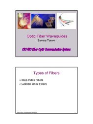
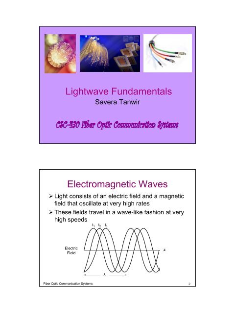
<strong>Lightwave</strong> <strong>Fundamentals</strong><br />
Savera Tanwir<br />
<strong>Electromagnetic</strong> <strong>Waves</strong><br />
‣ Light consists of an electric field and a magnetic<br />
field that oscillate at very high rates<br />
‣ These fields travel in a wave-like fashion at very<br />
high speeds<br />
t 1<br />
t 2<br />
t 3<br />
z<br />
Electric<br />
Field<br />
λ<br />
Fiber Optic Communication Systems 2
<strong>Electromagnetic</strong> <strong>Waves</strong><br />
‣Wave Number<br />
– Reciprocal of wavelength (1/λ)<br />
‣Electric Field<br />
– E = E 0 sin(ωt – kz)<br />
• E 0 = Field Amplitude<br />
• ω = Radian Frequency = 2πf radians/sec<br />
• k = Propagation Factor<br />
• z = distance traveled<br />
‣Propagation Factor<br />
– k = ω/v<br />
• v = velocity of the wave<br />
Fiber Optic Communication Systems 3<br />
‣Phase<br />
<strong>Electromagnetic</strong> <strong>Waves</strong><br />
– ωt – kz is the phase of the wave<br />
– kz is the phase shift owing to travel over<br />
length z<br />
– A plane wave is the one that has same phase<br />
over a planar surface<br />
Fiber Optic Communication Systems 4
<strong>Electromagnetic</strong> <strong>Waves</strong><br />
‣If t is constant<br />
– Sinusoidal spatial variation of the field<br />
– At t=0, E = -E 0 sin kz<br />
‣If position is fixed<br />
– Sinusoidal time variation of the field<br />
– At z=0, E=E 0 sin ωt<br />
Fiber Optic Communication Systems 5<br />
<strong>Electromagnetic</strong> <strong>Waves</strong><br />
‣Propagation Constant<br />
– k = ω/v<br />
– k = ωn/c (as v =c/n)<br />
– In free space n=1<br />
k 0 = ω/c<br />
– Thus<br />
k = k 0 n<br />
– Also k in terms of λ<br />
k = 2π/λ<br />
Fiber Optic Communication Systems 6
<strong>Electromagnetic</strong> <strong>Waves</strong><br />
‣Wavelength<br />
– λ = v/f<br />
– λ 0 = c/f<br />
– λ/ λ 0 = c/v = n<br />
– Thus, λ in a medium is shorter that in free<br />
space, because n > 1<br />
Fiber Optic Communication Systems 7<br />
Irradiance<br />
‣Power density is called irradiance. The<br />
units are watts/square meter<br />
‣Power in an optic beam is proportional to<br />
Intensity<br />
‣Intensity is defined as the square of<br />
electric field<br />
‣Intensity is proportional to irradiance<br />
Fiber Optic Communication Systems 8
Attenuation<br />
‣ Modification to the Electric field definition<br />
is required in case of attenuation<br />
‣ Correct Equation<br />
– E = E 0 e -αz sin(ωt – kz)<br />
• α = attenuation coefficient (losses in the fiber)<br />
• The value of α determines the rate at which the electric<br />
field diminishes as it travels through a lossy medium<br />
– Although the decay is exponential, the<br />
attenuation coefficient for quality fibers is so<br />
small that there is little attenuation, even over<br />
long paths<br />
Fiber Optic Communication Systems 9<br />
Attenuation<br />
Electric<br />
Field<br />
z<br />
Dashed Line Represents exp -αz<br />
Fiber Optic Communication Systems 10
‣Power<br />
Attenuation<br />
– As power is proportional to intensity, for a<br />
path of length L, the ratio of output power to<br />
input power in case of attenuation is<br />
exp(-2αL)<br />
– Power Reduction in dB<br />
dB = 10log 10 exp(-2αL)<br />
This will be negative in case of lossy medium<br />
Fiber Optic Communication Systems 11<br />
Attenuation<br />
‣Relation b/w α and power change<br />
dB/km = -8.685 α<br />
‣Beer’s Law<br />
–P out /P in = 10 γL/10<br />
L = path length<br />
γ = power change in dB/km<br />
Fiber Optic Communication Systems 12
Terminology<br />
‣ Line Width<br />
– Real sources produce radiation over a range of<br />
wavelengths. This range is called line width or<br />
spectral width.<br />
‣ Coherence<br />
– The smaller the line width the more coherent the<br />
source<br />
‣ Monochromatic source<br />
– A perfectly coherent source emits light at a single<br />
wavelength. Thus it has zero line width and it is<br />
perfectly monochromatic source.<br />
Fiber Optic Communication Systems 13<br />
Typical source spectral widths<br />
Source<br />
LED<br />
Laser Diode<br />
Nd:YAG laser<br />
HeNe Laser<br />
Line width (∆λ) (nm)<br />
20-100<br />
1 – 5<br />
0.1<br />
0.002<br />
‣ Laser diodes are more coherent than LEDs<br />
‣ The solid state neodymium yttrium-aluminum garnet laser and the<br />
helium-neon laser are even better<br />
‣ The small size and lower power requirements of LDs and LEDs<br />
make them more practicable for fiber systems, even though they<br />
have greater line-widths.<br />
Fiber Optic Communication Systems 14
‣The conversion between spectral width in<br />
wavelengths ∆λ and bandwidth in<br />
frequency ∆f is<br />
»∆f/f = ∆λ/λ<br />
» Where f is the center frequency and<br />
» λ is the center wavelength<br />
‣Spectrum<br />
– The wavelength or frequency content of a<br />
signal is called its spectrum<br />
The line width is normally taken to<br />
be the width to the half power<br />
points so here ∆λ = 30nm (805 – 835)<br />
Fiber Optic Communication Systems 15<br />
Dispersion<br />
‣ Dispersion is the "spreading" of a light pulse as it travels<br />
down a fiber<br />
‣ ν=c/n, where n is refractive index then<br />
‣ Dispersion is the property of velocity variation with<br />
wavelength<br />
Time<br />
Fiber Optic Communication Systems 16
Material Dispersion<br />
‣ When velocity variation is caused by some<br />
property of material.<br />
‣ For fibers and other waveguides, dispersion can<br />
also be caused by the structure themselves.<br />
This is called waveguide dispersion<br />
Fiber Optic Communication Systems 17<br />
Material Dispersion<br />
Pulse spreading caused by propagation through a dispersive material.<br />
Fiber Optic Communication Systems 18
Material Dispersion<br />
Dispersion causes loss in amplitude of an analog signal<br />
Fiber Optic Communication Systems 19<br />
Reducing Dispersion<br />
‣ Dispersion can be reduced by using sources<br />
with smaller bandwidths – that is by using more<br />
coherent emitters<br />
‣ LDs are better than LEDs<br />
‣ Filtering the light beam at the transmitter or<br />
receiver allowing only a narrow beam of<br />
wavelengths to reach the photodetector<br />
– Filters cant be constructed with passband narrow<br />
enough to be effective<br />
– A narrow band filter will greatly reduce the optic<br />
power by eliminating light at the unwanted<br />
wavelengths<br />
Fiber Optic Communication Systems 20
Material Dispersion<br />
Zero-Dispersive medium<br />
Dispersive medium<br />
τ is the time for a pulse to travel a path having length L.<br />
τ/L is the travel time/unit Length<br />
Fiber Optic Communication Systems 21<br />
Material Dispersion<br />
Fiber Optic Communication Systems 22
Material Dispersion of pure Silica<br />
Fiber Optic Communication Systems 23<br />
Example<br />
‣Find the amount of pulse spreading in<br />
pure silica for an LED operating at 0.82<br />
µm and having a 20 nm spectral width.<br />
‣The path is 10 Km long if λ =1.5 µm and<br />
λ∆=50nm.<br />
Fiber Optic Communication Systems 24
‣ Given<br />
Wavelength = 0.82 µm<br />
Spectral width ∆λ = 20 nm<br />
∆(τ/L) = ?<br />
∆(τ /L) = -M ∆λ<br />
Solution<br />
‣ M=110ps/(nm x km) ) at 0.82 µm.<br />
‣ ∆(τ/L)=110(20)<br />
‣ =2200ps/Km<br />
‣ =2.2ns/km<br />
‣ Spread of wavelength after 10 km = 10 * 2.2= 22<br />
ns.<br />
‣ Wavelength= 1.5 µm & ∆λ = 50 nm<br />
‣ M=15 ps/(nm x km)<br />
‣ ∆(τ /L)= 15 * 50 = 750 ps/km. = 0.75 ns/km<br />
‣ After 10 km the spread is 7.5 ns.<br />
Fiber Optic Communication Systems 25<br />
Example 2<br />
‣Repeat example 1 if the source is a laser<br />
diode with 1-nm width.<br />
∆(/T/L= -M*λ∆).<br />
The 10 km pulse spreads are then<br />
22/20 =1.1 ns at 0.82 µm<br />
the 7.5/50=015 ns at 1.5 µm<br />
Fiber Optic Communication Systems 26
Minimizing Pulse Spreading<br />
‣Pulse spreading reduces bandwidth and<br />
data capacity<br />
‣Solutions:<br />
– Operating at zero-dispersion<br />
– Coherent light source<br />
– Solitons<br />
Fiber Optic Communication Systems 27<br />
Solitons<br />
‣A soliton is a pulse that travels along a<br />
fiber without changing shape<br />
‣How?<br />
– Fiber Non-Linearity: Index of refraction depends on<br />
intensity of the light beam<br />
– Pulse velocity depends on index of refraction<br />
– So intensity of the beam can influence the speed of<br />
various wavelengths propagating along the fiber<br />
Fiber Optic Communication Systems 28
Solitons<br />
‣ The product of pulse energy and pulse width is<br />
constant.<br />
– The value of this constant depends on magnitude of<br />
dispersion and non-linearity<br />
‣ Therefore, solitons have shape, spectral content and<br />
power level designed to take advantage of nonlinear<br />
effects in an optical fiber waveguide<br />
Fiber Optic Communication Systems 29<br />
Information Rate<br />
‣ Pulse Spreading limits information rate<br />
‣ Consider a sinusoidal beam. Here modulation frequency<br />
is f and period is T=1/f.<br />
‣ Two optic wavelengths λ 1 and λ 2 are radiated<br />
‣ We know that modulated power carried at wavelengths<br />
between λ 1 and λ 2 will have delayed<br />
Canceling the modulation<br />
when two carrier wavelengths<br />
have a delay of half the<br />
modulation period<br />
Fiber Optic Communication Systems 30
Information Rate<br />
‣ When two carrier wavelengths have a delay of half the<br />
modulation period, they cancel<br />
‣ Delay has to be smaller than T/2<br />
‣ Max allowable pulse spread<br />
∆τ≤T/2<br />
2∆τ≤T<br />
Modulation frequency<br />
f=1/T=1/(2∆τ)=(2∆τ) -1<br />
Fiber Optic Communication Systems 31<br />
Information Rate<br />
‣ 3-dB bandwidth<br />
– Modulation frequency at which the signal power<br />
diminishes by half<br />
f 3-dB =(2∆τ) -1<br />
Frequency-length product<br />
f3-dB x L=1/2∆(τ/L)<br />
Fiber Optic Communication Systems 32
Information Rate<br />
‣ Total loss = L a + L f<br />
‣ Two Types<br />
–L a : fixed losses occur due to absorption and<br />
scattering<br />
–L f : due to modulation frequency<br />
Gaussian response<br />
– L f =-10 log {exp[-0.693 (f / f 3-dB ) 2 ]}<br />
– The loss is 1.5 dB at a frequency equal to<br />
0.71f 3-dB<br />
Fiber Optic Communication Systems 33<br />
Information Rate<br />
‣ f 1.5-dB = 0.71f 3-dB<br />
‣ f 1.5-dB (optic) = f 3-dB (electrical)<br />
= 0.71 f 3-dB (optic)<br />
– It corresponds to the frequency at which the<br />
electrical power in the receiver diminishes by half.<br />
‣f 3-dB (electrical)= 0.35/ ∆(τ)<br />
f 3-dB (electrical) x L= 0.35 / ∆(τ/L)<br />
Fiber Optic Communication Systems 34
Rate-length in digital signals<br />
In Return-to-Zero (RZ)<br />
R RZ =1/T= f 3-dB (electrical)= 0.35 / ∆(τ)<br />
or<br />
f 3-dB (electrical) x L= 0.35 / ∆(τ/L)<br />
In Non-Return-to-Zero (NRZ)<br />
R=1/T=2f<br />
R NRZ = 2 f 3-dB (electrical) = 0.71 / ∆(τ)<br />
R NRZ x L=0.71 / ∆(τ/L)<br />
Fiber Optic Communication Systems 35<br />
Example<br />
‣For conditions stated in example 1 & 2<br />
compute the rate-length and frequencylength<br />
product?<br />
Fiber Optic Communication Systems 36
Polarization<br />
‣ Polarization is the direction of electric field<br />
‣ An electric field that points in just one point is said to be<br />
linearly polarized<br />
‣ The direction of polarization is determined by the<br />
polarization of the light source<br />
‣ Mode refers to the different ways a wave can travel in a<br />
given direction<br />
‣ A wave is un polarized if electric vector varies randomly<br />
in direction<br />
E<br />
v<br />
Fiber Optic Communication Systems 37<br />
Resonant Cavities<br />
‣ Laser is light amplification through stimulated emission<br />
of radiation<br />
‣ To achieve laser action, it is necessary to contain<br />
photons in a laser medium and maintain condition for<br />
coherence<br />
‣ A laser consists of gain medium inside an optical cavity<br />
which supplies energy to gain medium<br />
Fiber Optic Communication Systems 38
Resonant Cavities<br />
‣ Gain medium (material e.g gas, liquid) transfers external<br />
energy into optical beam<br />
‣ A cavity consists of 2 mirrors that bounce light back and<br />
forth<br />
‣ Mirrors make sure that most light makes many passes<br />
through the gain medium<br />
‣ One of the mirrors is partially transparent to output laser<br />
beam<br />
Fiber Optic Communication Systems 39<br />
Resonant Cavities<br />
‣ Oscillation occur over a small range of frequencies<br />
where the cavity gain is sufficient to overcome the losses<br />
‣ Radiation in the cavity builds up like standing waves<br />
between the mirrors.<br />
‣ The standing waves exist at specific frequencies called<br />
resonant frequencies<br />
Fiber Optic Communication Systems 40
‣ L = λm/2<br />
Resonant Frequencies<br />
‣ λ = 2L/m<br />
‣ f = mc/2nL<br />
‣ ∆f c = c/2Ln<br />
‣ ∆λ c = λ o2 ∆f c / c<br />
Fiber Optic Communication Systems 41<br />
Example 3-7<br />
Fiber Optic Communication Systems 42
Reflection<br />
A B C D<br />
‣Reflection coefficient<br />
ρ = n1 – n2 / n1 + n2<br />
‣ Reflectance<br />
R = (n1 – n2 / n1 + n2) 2<br />
Fiber Optic Communication Systems 43<br />
Critical Angle<br />
‣ When light travels from denser medium to rarer<br />
the refracted beam bends away from the normal<br />
‣ The incidence angle at which transmitted angle<br />
is 90 o is critical angle<br />
‣ At angles greater than critical angle total internal<br />
reflection takes place<br />
Fiber Optic Communication Systems 44
Critical Angles<br />
Boundary<br />
n1<br />
n2<br />
θ c<br />
Glass- air<br />
1.5<br />
1.0<br />
41.8<br />
Plastic - plastic<br />
1.49<br />
1.39<br />
68.9<br />
Glass - plastic<br />
1.46<br />
1.4<br />
73.5<br />
Glass – glass<br />
1.48<br />
1.46<br />
80.6<br />
Fiber Optic Communication Systems 45