Classic - Airstream
Classic - Airstream
Classic - Airstream

Create successful ePaper yourself
Turn your PDF publications into a flip-book with our unique Google optimized e-Paper software.
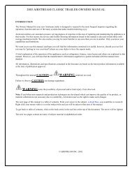
INTRODUCTION<br />
The Owners Manual for your new <strong>Airstream</strong> trailer is designed to respond to<br />
the most frequent inquiries regarding the operation, function and care of the<br />
many systems that make modern trailering a joy.<br />
<strong>Airstream</strong> realizes our customers possess varying degrees of expertise in the<br />
area of repairing and maintaining the appliances in their trailer. For this reason,<br />
the service and trouble-shooting information found in this manual is directed<br />
toward those with average mechanical skills.<br />
We also realize you may be more familiar in one area than you are in another.<br />
Only you know your capabilities and limitations. We want you to use this<br />
manual, and hope you will find the information contained in it useful, however,<br />
should you ever feel you may be “getting in over your head” please see your<br />
dealer to have the repairs made.<br />
A brief explanation of the operation of the appliances such as refrigerator,<br />
furnace, water heater and others are explained in this manual. However, you<br />
will also find the manufacturer’s information supplied in a packet included<br />
with this manual more detailed.<br />
All information, illustrations and specifications contained in this manual are based<br />
on the latest product information available at the time of publication approval. If<br />
and when new materials and production techniques are developed which can
INTRODUCTION<br />
2014 CLASSIC<br />
improve the quality of its product, or material substitutions are necessary due<br />
to availability, <strong>Airstream</strong> reserves the right to make such changes.<br />
We have provided many important safety messages in this manual. Always<br />
read and obey all safety messages.<br />
cannot be added.<br />
The inclusion of optional items does not imply or suggest the availability,<br />
application suitability, or inclusion for any specific unit.<br />
Important Safety Precautions<br />
Warning indicates a potentially hazardous situation that, if not<br />
avoided, could result in death or serious injury.<br />
You’ll find many safety recommendations on this page and throughout this<br />
manual. The following recommendations are the ones we consider to be the<br />
most important. Most are covered in depth in later sections of this manual.<br />
CAUTION indicates a potentially hazardous situation that, if not<br />
avoided, could result in minor or moderate injury.<br />
NOTICE: used without the safety alert symbol indicates a situation that could<br />
result in property damage if not avoided.<br />
Do Not Allow Passengers to Ride in the Trailer During Travel<br />
The transport of people puts their lives at risk and may be illegal. The trailer<br />
does not have seat belts, therefore, it is not designed to carry passengers.<br />
Reducing Fishtailing or Sway (See section B-12)<br />
NOTE: Important information regarding the maintenance of your recreational<br />
vehicle.<br />
(Optional)<br />
This denotes items that may be an option on all or particular models. Additionally,<br />
some optional items can only be included during the manufacturing phase and<br />
Sway or fishtailing is the sideways action of a trailer caused by external forces.<br />
Excessive sway of your travel trailer can lead to the rollover of the trailer and<br />
tow vehicle resulting in serious injury or death. Be sure to follow the instructions<br />
in this manual.
INTRODUCTION<br />
Mold (See page C-9)<br />
There are mold and mold spores throughout the indoor and outdoor environment.<br />
There is no practical way to eliminate all mold and mold spores in the indoor<br />
environment; the way to control indoor mold growth is to control moisture.<br />
Towing and Weight Distribution (See page B-1)<br />
Weight distribution is an important factor when loading your travel trailer. A<br />
recreational vehicle with the cargo distributed properly will result in efficient,<br />
trouble-free towing. Be sure to follow the instructions in this manual.<br />
Generator Safety<br />
Do not operate the generator in an enclosed building or in a partly enclosed<br />
area such as a garage. Nor should the generator be operated while sleeping.<br />
Be sure to follow all instructions and warnings in this manual.<br />
Lug Nut Torquing (See page D-16)<br />
Being sure wheel mounting nuts (lug nuts) on trailer wheels are tight and<br />
properly torqued is an important responsibility that trailer owners and users<br />
need to be familiar with and practice. Inadequate and/or inappropriate wheel<br />
nut torque (tightness) is a major reason that lug nuts loosen in service. Loose<br />
lug nuts can rapidly lead to a wheel separation with potentially serious safety<br />
consequences. Be sure to follow the instructions in this manual.<br />
WHEEL SEPARATION CAN OCCUR<br />
On first trip, tighten wheel nuts at start of first trip and at 10, 25, and 50<br />
miles. Thereafter check wheel nut torque: Before each trip, Following<br />
winter storage, Following excessive braking, or whenever a wheel is<br />
removed and replaced.<br />
See torque pattern on page D-16 for tightening sequence and follow torque<br />
specifications on page I-2.<br />
Appliances and Equipment (See page H-1)<br />
The appliances (stove, refrigerator, etc.) and equipment (hot water heater,<br />
furnace generator, etc.) typically operate on Propane gas. Propane gas is<br />
flammable and is contained under high pressure. Improper use may result<br />
in a fire and/or explosion. Be sure to follow all instructions and warnings in<br />
this manual as well as the specific owners’ manuals of the appliances and<br />
equipment.
INTRODUCTION<br />
2014 CLASSIC<br />
Tire Safety<br />
Properly maintained tires improve the steering, stopping, traction, and loadcarrying<br />
capability of your vehicle. Under inflated tires and overloaded<br />
vehicles are a major cause of tire failure. Be sure to read the Tire Safety Manual<br />
Addendum included with your owner’s packet.<br />
Chemical Sensitivity<br />
After you first purchase your new recreational vehicle and sometimes after it<br />
has been closed up for an extended period of time you may notice a strong<br />
odor and chemical sensitivity. This is not a defect in your recreational vehicle.<br />
Like your home, there are many different products used in the construction of<br />
recreational vehicles such as carpet, linoleum, plywood, insulation, upholstery,<br />
etc. Formaldehyde is also the by-product of combustion and numerous<br />
household products, such as some paints, coatings and cosmetics. However,<br />
recreational vehicles are much smaller than your home and therefore the<br />
exchange of air inside a recreational vehicle is significantly less than a home.<br />
These products, when new or when exposed to elevated temperatures and/<br />
or humidity, may “off-gas” different chemicals, including formaldehyde. This<br />
off-gassing, in combination with the minimal air exchange, may cause you to<br />
experience irritation of the eyes, nose, and throat and sometimes headache,<br />
nausea, and a variety of asthma-like symptoms. Elderly persons and young<br />
children, as well as anyone with a history of asthma, allergies, or lung problems,<br />
may be more susceptible to the effects of off-gassing.<br />
Formaldehyde<br />
Most of the attention regarding chemical off-gassing surrounds formaldehyde.<br />
Formaldehyde is a naturally occurring substance and is an important chemical<br />
used widely by industry to manufacture building materials and numerous<br />
household products. It is also a by-product of combustion and certain<br />
other natural processes. Thus, it may be present inside the trailer with some<br />
individuals being sensitive to it. Ventilation of the unit normally reduces the<br />
exposure to a comfortable level.<br />
Trace levels of formaldehyde are released from smoking, cooking, use of<br />
soaps and detergents such as carpet shampoos, cosmetics, and many other<br />
household products. Some people are very sensitive to formaldehyde while<br />
others may not have any reaction to the same levels of formaldehyde. Amounts<br />
released decrease over time.<br />
Your <strong>Airstream</strong> trailer was manufactured using low formaldehyde emitting (LFE)<br />
wood products, which is the typical usage in the recreation vehicle industry.<br />
Formaldehyde has an important role in the adhesives used to bind wood<br />
products used in recreation vehicles. The wood products in your trailer are
INTRODUCTION<br />
designed to emit formaldehyde at or lower than industry guidelines and should<br />
not produce symptoms in most individuals.<br />
While LFE wood products typically do not emit formaldehyde at a level that<br />
would cause symptoms in most individuals, it is possible, though not likely, for<br />
that to occur when the trailer is not properly ventilated. Ventilation is an essential<br />
requirement for trailer use, for many reasons. Any effects of formaldehyde<br />
can be greatly reduced by actions such as opening windows, opening roof<br />
vents, running the air conditioner, or some combination thereof. In addition,<br />
the emission of formaldehyde by these products naturally decreases rapidly<br />
over time.<br />
<strong>Airstream</strong> strongly suggests that you take measures to properly ventilate your<br />
trailer on a regular basis. If you have any questions with respect to proper<br />
ventilation of your trailer, please do not hesitate to contact your dealer or<br />
<strong>Airstream</strong>.<br />
Ventilation<br />
To reduce or lessen exposure to chemicals from off-gassing it is of utmost<br />
importance that you ventilate your recreational vehicle. Ventilation should occur<br />
frequently after purchase and at times when the temperatures and humidity are<br />
elevated. Remember off-gassing is accelerated by heat and humidity. Open<br />
windows, exhaust vents, and doors. Operate ceiling and/or other fans, roof air<br />
conditioners, and furnaces and use a fan to force stale air out and bring fresh air<br />
in. Decreasing the flow of air by sealing the recreational vehicle increases the<br />
formaldehyde level in the indoor air. Please also follow the recommendations<br />
contained in Chapter 2 regarding tips to avoid condensation problems. Many<br />
of the recommendations contained in Chapter 2 will assist in avoiding exposure<br />
to chemicals that off-gas.<br />
Do Not Smoke<br />
Finally, we recommend that you do not smoke inside your recreational vehicle.<br />
In addition to causing damage to your recreational vehicle, tobacco smoke<br />
releases formaldehyde and other toxic chemicals.<br />
Medical Advice<br />
If you have any questions regarding the health effects of formaldehyde, please<br />
consult your doctor or local health department.<br />
Warranty Exclusion<br />
Chemical gassing is not a “Defect” in your recreational vehicle and is not<br />
covered by the Limited Warranty. Please follow the recommendations in this<br />
manual to address this concern.
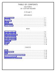
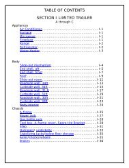
TABLE OF CONTENTS<br />
A. WARRANTY AND SERVICE<br />
Hook Ups<br />
Main Door<br />
H. APPLIANCES<br />
Winter Traveling<br />
Exterior Windows Screens<br />
Warranty<br />
Air Conditioner<br />
Warranty Explanation<br />
D. EXTERIOR<br />
F. PLUMBING<br />
Furnace<br />
Service<br />
Range/Oven<br />
Reporting Safety Defects<br />
Cleaning<br />
LP (Liquid Petroleum) Gas<br />
Microwave<br />
Maintenance Schedule<br />
Chassis<br />
Water<br />
Refrigerator<br />
Maintenance Parts & Supplies<br />
Power Jack<br />
Drainage<br />
Water Heater<br />
Tires<br />
Winterizing<br />
Roof Vent, High Volume<br />
B. TOWING<br />
Axle and Running Gear<br />
Drain and Waste<br />
Brakes<br />
Toilet<br />
I. SPECIFICATIONS<br />
Tow Vehicles<br />
Tires<br />
Brakes<br />
G. ELECTRICAL<br />
Loading<br />
E. INTERIOR FURNISHINGS<br />
Weighing<br />
AND ACCESSORIES<br />
Battery<br />
Hitching Up<br />
Converter<br />
Fabric Care<br />
12-Volt System & Components<br />
C. CAMPING<br />
Lounges & Tables<br />
TV Antenna<br />
Features & Fixtures<br />
Satellite Antenna<br />
Pre-Travel Check List<br />
Storage Areas<br />
Solar Panel<br />
Camping Safety<br />
Smoke Alarm<br />
Bathroom Exhaust<br />
Overnight Stop/Extended Stay<br />
Gas Detector<br />
Monitor Panel<br />
Leveling & Stabilizing<br />
Fire Extinguisher<br />
110-Volt System & Components
AIRSTREAM LIMITED WARRANTY<br />
WARRANTY COVERAGE<br />
<strong>Airstream</strong> Inc. (“<strong>Airstream</strong>”) warrants that it will repair or replace defects<br />
in material or workmanship in any components of a new <strong>Airstream</strong> trailer<br />
purchased from an authorized <strong>Airstream</strong> dealer in the United States or<br />
Canada for a period of twenty-four (24) months from the date the trailer is first<br />
delivered to the original retail purchaser. In order to obtain coverage under<br />
this Limited Warranty, you must notify an authorized <strong>Airstream</strong> dealership<br />
or <strong>Airstream</strong> of the warrantable defect no later than ten (10) days following<br />
expiration of this Limited Warranty. <strong>Airstream</strong>’s obligation to repair or replace<br />
defective materials or workmanship is the sole obligation of <strong>Airstream</strong> under<br />
this Limited Warranty. <strong>Airstream</strong> reserves the right to use new or remanufactured<br />
parts of similar quality to complete any warranty work.<br />
LIMITATION OF IMPLIED WARRANTIES<br />
IMPLIED WARRANTIES ARISING UNDER APPLICABLE LAW, IF<br />
ANY, INCLUDING BUT NOT LIMITED TO IMPLIED WARRANTIES OF<br />
MERCHANTABILITY OR FITNESS FOR A PARTICULAR PURPOSE,<br />
ARE HEREBY LIMITED IN DURATION TO THE TERM OF THIS LIMITED<br />
WARRANTY. ALL OTHER WARRANTIES, EXPRESS OR IMPLIED, ARE<br />
HEREBY DISCLAIMED BY AIRSTREAM. SOME STATES DO NOT ALLOW<br />
LIMITATIONS ON HOW LONG AN IMPLIED WARRANTY LASTS, SO THE<br />
ABOVE LIMITATIONS MAY NOT APPLY TO YOU.<br />
Warranty and Service<br />
WHAT IS NOT COVERED BY THIS LIMITED WARRANTY<br />
This Limited Warranty does not provide coverage for any of the following:<br />
1. Tires, batteries, stereo, television, range/stove, furnace, refrigerator, water<br />
heater, microwave, generator, slide-out mechanisms, and other materials,<br />
parts and components warranted by persons or entities other than <strong>Airstream</strong>.<br />
Please refer to the warranties of component manufacturers for terms and<br />
conditions of coverage;<br />
2. Any part or component of the trailer that was not manufactured or installed<br />
by <strong>Airstream</strong>;<br />
3. Normal deterioration due to wear or exposure, including but not limited to<br />
rust, corrosion, oxidation, and cosmetic blemishes;<br />
4. Normal maintenance and service items, including but not limited to light<br />
bulbs, fuses, lubricants, sealants and seals, slideout adjustments, door<br />
adjustments, and awning tension;<br />
5. After-market equipment or accessories installed on the trailer after completion<br />
of manufacture by <strong>Airstream</strong>, or any defects or damage caused by such<br />
items;<br />
6. Trailers not purchased through an authorized dealer of <strong>Airstream</strong> trailers,<br />
and trailers purchased directly or indirectly through auction, salvage, repossession,<br />
or other non-customary sale means;<br />
7. Defects or damage caused by, in whole or in part, or in any way related to:<br />
a. Accidents, misuse (including off-road use), or negligence.<br />
b. Failure to comply with the instructions set forth in any owner’s manual<br />
A<br />
A - 1
A<br />
Warranty and Service<br />
provided with the trailer.<br />
c. Alteration or modification of the trailer except such alterations or modifications<br />
approved in writing by <strong>Airstream</strong>.<br />
d. Acts of God or other environmental conditions, such as lightning, hail, salt,<br />
or other chemicals in the atmosphere.<br />
e. De-icing agents or other chemicals applied to the trailer.<br />
f. Failure to properly maintain or service the trailer, including but not limited to<br />
the maintenance of lubricants, sealants, and seals.<br />
g. Condensation and the results of condensation including water damage<br />
and the growth of mold or mildew. Mold and mildew are natural<br />
growths given certain environmental conditions and are not covered by the<br />
terms of this Limited Warranty.<br />
h. Use of the trailer other than for temporary recreation purposes, including<br />
but not limited to use of the trailer for residential, disaster relief,<br />
commercial, or rental purposes.<br />
i. The addition of weight to the trailer that causes the trailer’s total weight to<br />
exceed applicable trailer weight ratings, or addition of weight<br />
causing improper distribution of the weight of the trailer.<br />
j. Selection, use, and operation of any hitch assembly.<br />
k. Failure to seek and obtain repairs in a timely manner.<br />
l. Failure to use reasonable efforts to mitigate damage caused by defects.<br />
m. Failure to properly ventilate the trailer.<br />
n. Improper electric power supply or improper vehicle hookup to other facilities.<br />
o. Acts or omissions of any person or entity other than <strong>Airstream</strong>.<br />
DISCLAIMER OF INCIDENTAL AND CONSEQUENTIAL DAMAGES<br />
<strong>Airstream</strong> hereby disclaims any and all incidental and consequential damages<br />
arising out of or relating to the trailer, including expenses such as transportation<br />
to and from vehicle dealerships and <strong>Airstream</strong> repair facilities, loss of<br />
time, loss of pay, loss of use, inconvenience, commercial loss (including<br />
lost profits), towing charges, bus fares, vehicle rental, service call charges,<br />
gasoline expenses, incidental charges such as telephone calls and facsimile<br />
transmissions, and expenses for lodging. This disclaimer is independent of<br />
any failure of the essential purpose of any warranties provided with a trailer,<br />
and shall survive any determination that a warranty failed of its essential<br />
purpose. Some states do not allow the exclusion or limitation of incidental or<br />
consequential damages, so the above limitation or exclusion may not apply<br />
to you.<br />
OBTAINING WARRANTY SERVICE<br />
In order to obtain warranty service under this Limited Warranty, the owner<br />
must do all of the following:<br />
1. Owner and dealer representative must complete and return the Customer<br />
Performance Checkout within 10 days from delivery of the trailer;<br />
2. Notify <strong>Airstream</strong> or one of its authorized, independent dealers, of any<br />
A - 2
claimed defect within the warranty period or 10 days thereafter;<br />
3. Provide notification of a defect within 10 days of discovery of that defect;<br />
4. Promptly return the trailer to an authorized <strong>Airstream</strong> dealer or <strong>Airstream</strong> for<br />
repairs.<br />
If you believe a defect covered by this Limited Warranty still exists after an attempted<br />
repair by an authorized <strong>Airstream</strong> dealer, you must contact <strong>Airstream</strong><br />
at the following address, specifying:<br />
1. The complete serial number of the trailer;<br />
2. The date of original purchase and the date of original delivery;<br />
3. The name of the selling dealer; and<br />
4. The nature of the problem and the steps or service which have been<br />
performed.<br />
AIRSTREAM, INC.<br />
419 West Pike Street<br />
P.O. Box 629<br />
Jackson Center, Ohio 45334-0629<br />
Attention: Owner Relations Department<br />
<strong>Airstream</strong> may direct you to an authorized <strong>Airstream</strong> dealer, or may request<br />
that you bring your trailer to the <strong>Airstream</strong> factory in Jackson Center, Ohio for<br />
repairs.<br />
Warranty and Service<br />
<strong>Airstream</strong> does not control the scheduling of repairs at its authorized<br />
<strong>Airstream</strong> dealers, and repairs at the <strong>Airstream</strong> factory may not be immediately<br />
available. Therefore, you may encounter delays in scheduling repairs<br />
and/or completion of repairs. All costs associated with transporting the trailer<br />
for any warranty service shall be the sole responsibility of the owner.<br />
DEALER REPRESENTATIONS EXCLUDED<br />
The entire Limited Warranty provided by <strong>Airstream</strong> is set forth herein.<br />
<strong>Airstream</strong> will not be responsible for any additional representations or warranties<br />
made by any person or entity other than <strong>Airstream</strong>, and <strong>Airstream</strong>’s<br />
obligations are solely as set forth in the terms and conditions of this Limited<br />
Warranty.<br />
WARRANTY TRANSFER<br />
This Limited Warranty is transferable to subsequent owners for the remaining<br />
duration of the warranty period, upon approval from <strong>Airstream</strong>. Transfer of this<br />
Limited Warranty will only be approved by <strong>Airstream</strong> upon all of the following:<br />
1. <strong>Airstream</strong>’s receipt of a completed transfer application form;<br />
2. The payment of a $250.00 processing fee to <strong>Airstream</strong>; and<br />
3. The completion of an inspection of the condition of the trailer, at the<br />
owner’s expense, by an authorized <strong>Airstream</strong> dealer in accordance with<br />
<strong>Airstream</strong>’s required procedure and <strong>Airstream</strong>’s receipt of a written report as<br />
to the results of such inspection.<br />
A<br />
A - 3
A<br />
Warranty and Service<br />
Transfer application forms are available from your dealer or <strong>Airstream</strong>’s<br />
Service Administration Department.<br />
CHANGES IN DESIGN<br />
<strong>Airstream</strong> reserves the right to make changes in design and improvements<br />
upon its products from time-to-time, without imposing upon itself any obligation<br />
to install additional features in your trailer.<br />
STATUTE OF LIMITATIONS<br />
No action may be brought against <strong>Airstream</strong> for breach of this Limited<br />
Warranty, any applicable implied warranty, or for any other claim arising out of<br />
or relating to an <strong>Airstream</strong> trailer, more than thirty (30) days after: (1) expiration<br />
of the twenty-four (24) month Limited Warranty period; or (2) expiration of<br />
the ten (10) day notice period that follows expiration of the Limited Warranty<br />
period, if such notice is given.<br />
EXPLANATION OF AIRSTREAM LIMITED WARRANTY<br />
The <strong>Airstream</strong> Limited Warranty is detailed on a Warranty Card. It is filled out<br />
by the dealer and presented to the owner during delivery of a new unit. The<br />
Limited Warranty must be presented to a dealer to obtain warranty service. It<br />
should be kept in the trailer during the warranty period.<br />
EXCLUSIONS:<br />
Normal Wear<br />
Items such as tires, curtains, upholstery, floor coverings, window, door and<br />
vent seals will show wear or may even wear out within the one year warranty<br />
period depending upon the amount of usage, weather, and atmospheric<br />
conditions.<br />
THIS WARRANTY GIVES YOU SPECIFIC LEGAL RIGHTS, AND YOU MAY<br />
ALSO HAVE OTHER RIGHTS WHICH VARY FROM STATE TO STATE.<br />
AIRSTREAM, INC.<br />
419 West Pike Street<br />
P.O. Box 629, Jackson Center, OH 45334-0629<br />
Tele: 937-596-6111<br />
Fax: 937-596-6539<br />
Accident<br />
We strongly urge our dealers and customers to inspect the trailer upon receipt<br />
of delivery for any damage caused by accident while being delivered to<br />
the dealer, or while it is on the dealer’s lot. Damage of this nature becomes<br />
the dealer or customer’s responsibility upon acceptance of delivery, unless<br />
<strong>Airstream</strong> is notified and the person making the delivery verifies the damage.<br />
A - 4
Glass breakage, whether obviously struck or mysterious, is always accidental<br />
and covered by most insurance policies.<br />
Abuse<br />
Lack of customer care and/or improper maintenance will result in early failure<br />
for which <strong>Airstream</strong> cannot be held responsible.<br />
Exposure<br />
Not unlike a car, the steel parts of a trailer can and will rust if subjected to<br />
prolonged exposure to moisture, salt air, or corrosive air-borne pollutants<br />
without repainting. Aluminum oxidizes when unprotected under similar conditions,<br />
and refinery chemicals of a sulfurous nature are harmful to finishes if not<br />
washed off periodically. Extremely hot or direct sunlight will deteriorate rubber<br />
and fade curtains and upholstery. Conditions of this nature, although they<br />
may be normal for the area, are beyond <strong>Airstream</strong>’s control and become the<br />
responsibility of the owner.<br />
Warranty and Service<br />
upholstery, carpeting, or drapes; mold formation and growth; furniture<br />
damage, etc. Mold is a natural growth given certain environmental conditions<br />
and is not covered by the terms of the Limited Warranty.<br />
Overload<br />
Damage due to loading, either beyond capacity or to cause improper towing<br />
because of improper balance, is beyond <strong>Airstream</strong>’s responsibility. The<br />
<strong>Airstream</strong> trailer is engineered to properly handle the gross vehicle load<br />
rating on the certification label. Load distribution has a definite effect upon<br />
the towing characteristics and attitudes of the trailer. Level hitch installations<br />
are a necessity, and very important on a tandem axle trailer. There are limits<br />
to the amount of load that can be safely transported depending upon speed<br />
and road conditions, and reasonable cause to believe these factors have<br />
been exceeded could void the <strong>Airstream</strong> warranty. For additional information<br />
on the loading of your trailer, consult your Owner’s Manual or gross vehicle<br />
weight rating plate.<br />
A<br />
It is the responsibility of the owner to take such preventative measures as<br />
are necessary to maintain the exterior caulking and sealer of your unit. It is<br />
the responsibility of the owner to use reasonable, prudent care to prevent<br />
foreseeable secondary damage from rain, plumbing leaks, and the natural<br />
accumulation of moisture in your unit, such as a delaminated floor; stained<br />
The axle is manufactured to a tolerance of 1-degree camber and 1/8” toe-in.<br />
These tolerances will only change if the trailer is subjected to abuse, such<br />
as dropping off a sharp berm, striking a curb, or hitting a deep hole in the<br />
road. Such damage could be considered as resulting from an accident which<br />
risks are not covered under the warranty. Abnormal tire wear and/or wheel<br />
A - 5
A<br />
Warranty and Service<br />
alignment resulting from such damage is not covered under the terms of the<br />
warranty.<br />
Chemical Gassing<br />
Chemical gassing is not a “Defect” in your recreational vehicle and is not<br />
covered by the Limited Warranty. Please follow the recommendations in this<br />
manual to address this concern.<br />
SERVICE:<br />
Before leaving the factory, each and every vital part of the trailer is tested<br />
for performance. Each test is signed and certified by an inspector. After the<br />
trailer arrives on your dealer’s lot all of these vital parts and systems are again<br />
tested. When you take delivery of your new trailer you will receive a complete<br />
check out.<br />
At that time a specified list of performance checks on your trailer equipment<br />
will be conducted and any deficiencies you have experienced since taking<br />
delivery will be corrected.<br />
Please contact your dealer if you need service. Major service under your<br />
<strong>Airstream</strong> Limited Warranty is available through our nationwide network of<br />
<strong>Airstream</strong> Dealer Service Centers. An up-to-date list of Dealer Service Centers<br />
will be sent with an Owner’s Survey shortly after your trailer is delivered.<br />
WWW.<strong>Airstream</strong>.com web site also has a dealer locator on it. This list is current<br />
as of the date of this publication.<br />
Occasionally dealerships change, or new dealers are added who may not<br />
appear on this list. For this reason, it is suggested that you contact your local<br />
dealer from time to time and bring your list up to date. He can also provide<br />
you with additional copies if you need them. ALL CENTERS OPERATE ON AN<br />
APPOINTMENT BASIS FOR THE UTMOST EFFICIENCY.<br />
When you require service from the <strong>Airstream</strong> Factory Service Center, or a<br />
Certified Dealer Service Center, please contact the service manager for an<br />
appointment, and kindly inform him if you are unable to keep the appointment<br />
date or wish to change it. Service may be arranged at the Factory Service<br />
Center by contacting the Service Coordinator at: <strong>Airstream</strong> Factory Service<br />
Center, P.O. Box 629, 419 W. Pike Street, Jackson Center, Ohio 45334-0629<br />
Phone: 937-596-6111<br />
REPORTING SAFETY DEFECTS<br />
If you believe that your vehicle has a defect which could cause a crash or<br />
could cause injury or death, you should immediately inform the National<br />
Highway Traffic Safety Administration (NHTSA) in addition to notifying<br />
<strong>Airstream</strong> Inc..<br />
A - 6
If NHTSA receives similar complaints, it may open an investigation, and<br />
if it finds that a safety defect exists in a group of vehicles, it may order a<br />
recall and remedy campaign. However, NTHSA cannot become involved in<br />
individual problems between you, your dealer, or <strong>Airstream</strong> Inc.<br />
To contact NHTSA, you may either call the Vehicle Safety Hotline toll-free at<br />
1-888-327-4236 (TTY: 1-800-424-9153); go to http://www.safercar.gov; or<br />
write to: Administrator, NHTSA, 1200 New Jersey Avenue S.E., Washington,<br />
DC 20590.<br />
Warranty and Service<br />
SUGGESTED MAINTENANCE<br />
EVERY 1,000 MILES OR 60 DAYS<br />
Escape Window<br />
Check operation of latches and upper hinge.<br />
*Battery<br />
Check water level<br />
Smoke Alarm<br />
Test and replace battery as required<br />
A<br />
You can also obtain other information about motor vehicle safety from http://<br />
www.safercar.gov.<br />
MAINTENANCE SCHEDULE<br />
Warning: FAILURE TO MAINTAIN YOUR COACH CAN CAUSE<br />
PREMATURE AND UNEXPECTED PARTS BREAKAGE AND/OR ERRATIC<br />
OPERATION THAT MAY BE HAZARDOUS.<br />
Note: See appliance manufacturer’s literature for further information.<br />
Tires<br />
Check tire pressure (See Specifications)<br />
Hitch<br />
Check for loose bolts or unusual wear.<br />
GFI Circuit Breaker<br />
Test and record.<br />
Warning: WHEEL SEPARATION CAN OCCUR<br />
1. On first trip, tighten wheel nuts at start and at 10, 25, and 50 miles.<br />
2. Thereafter, check wheel nuts before each trip.<br />
3. Following winter storage, check before beginning a trip.<br />
4. Following excessive braking, inspect wheel nuts<br />
See Specification Section in this manual for wheel torque ratings.<br />
A - 7
Warranty and Service<br />
EVERY 5,000 MILES OR 90 DAYS<br />
Range Exhaust Hood<br />
Clean fan blades and wash filter.<br />
A<br />
Exterior Door locks<br />
Exterior Hinges<br />
Lubricate with dry graphite<br />
Lubricate with light household oil<br />
Roof Vent Elevator Screws<br />
Main Door Step<br />
Lubricate with light household oil<br />
Lubricate moving parts and check.<br />
LPG Hold Down<br />
LPG Regulator<br />
Lubricate with light household oil<br />
Check bottom vent for obstructions<br />
* As a battery ages and becomes less efficient, the water level should be<br />
checked at more frequent levels.<br />
Main Door Striker Pocket<br />
Coat with paraffin.<br />
Wheel Lug Nuts<br />
Break Away Switch<br />
See Specification Section in this manual for<br />
wheel torque ratings.<br />
Pull pin and lubricate with household oil<br />
Replace pin immediately.<br />
7-Way Plug<br />
Spray with contact cleaner.<br />
Hitch Ball Latch<br />
Lubricate with non-detergent motor oil<br />
Hitch Ball<br />
Lubricate with hitch ball lube or wheel bearing<br />
grease.<br />
A - 8
Warranty and Service<br />
EVERY 10, 000 MILES OR 6 MONTHS<br />
EVERY YEAR<br />
Brakes<br />
Inspect, replace as necessary<br />
Battery<br />
Clean, neutralize and coat terminals<br />
with petroleum jelly.<br />
A<br />
Tires<br />
Inspect and rotate<br />
A-Frame, Step<br />
Wire brush and paint frame at front and rear.<br />
Spare Tire Carrier<br />
Lubricate moving parts.<br />
LP Bottles<br />
Have purged by LP supplier.<br />
Seals, Windows & Door<br />
Clean with mild detergent and coat with “Slipi<br />
Seams<br />
Check and reseal exterior seams, windows,<br />
cone”.<br />
lights and vents if necessary. Use Ten X or<br />
equivalent.<br />
TV Antenna<br />
Lubricate all moving parts with silicone lubri<br />
cant.<br />
Hitch Coupler and Ball<br />
Check for wear or damage. Assure all parts<br />
operate freely. Replace any component if<br />
Exterior<br />
Wax<br />
worn or damaged.<br />
Escape Window<br />
Lubricate latches with WD-40.<br />
LP Bottles<br />
Check tightness of center hold down rod where<br />
it fastens to A-Frame<br />
A - 9
Warranty and Service<br />
PARTS AND LUBRICANTS<br />
FUSES<br />
A<br />
BULBS, EXTERIOR<br />
Taillight, Back Up, License Plate<br />
LED, Sealed, replace light<br />
Clearance Light, Door Light<br />
LED, Sealed, replace light<br />
Scare Light<br />
LED, Sealed, replace light<br />
Hitch Light<br />
# 193, wedge base<br />
Single Bulb Compartment light w/switch 12V LED, WP 05-0005<br />
BULBS, INTERIOR<br />
Shower light, single dome, wet location LED, L05-0035<br />
Single Bulb light w/switch LED, WP 05-0005<br />
Two-Bulb Pin Up Light #1076<br />
3 Arm Dinette Light #921<br />
Wall Light #1076<br />
Reading & Ceiling Light #819<br />
Warning: Always replace the bulb or light fixture with the<br />
correct bulb for that light or matching fixture. Failure to heed this<br />
warning could cause fire, property damage, personal injury, or death.<br />
ATC 15 & 20 Amp<br />
Battery Cable Fuses SLC 50 Amp (Canadian approved trailers only)<br />
MISCELLANEOUS<br />
Water Hose Gaskets<br />
Wheel Bearing Grease (for hitch ball)<br />
Extra Hair Pin Clips for Hitch<br />
Dry Graphite<br />
WD-40 or Equivalent Aerosol Lubricant<br />
Oil Can with 30 Weight Non-Detergent Oil<br />
Silicone Lubricant<br />
Light Household Type Oil<br />
Spray Contact Cleaner<br />
Sealer<br />
C & D-Cell Batteries<br />
Flashlight<br />
Rain Gear<br />
Road Hazard Signals<br />
A - 10
Warranty and Service<br />
Maintenance Record<br />
Date<br />
Dealer<br />
Service<br />
Performed<br />
Date<br />
Dealer<br />
Service<br />
Performed<br />
A<br />
A - 11
Warranty and Service<br />
NOTES<br />
A<br />
A - 12
TOWING YOUR AIRSTREAM<br />
Tow Vehicle Equipment<br />
If you plan to buy a new vehicle to tow your trailer we suggest that you include<br />
in your purchase the towing options offered by most vehicle manufacturers.<br />
These include such things a heavy-duty alternator and radiator, heavy-duty<br />
springs, (See Note:) shock absorbers, transmission cooler, heavy-duty fan and<br />
flasher unit and others, depending upon the make of the vehicle.<br />
NOTICE: Be realistic when ordering heavy duty springs. Only springs heavy<br />
enough to support your loaded vehicle (not including trailer) are necessary. Too<br />
harsh of spring rate will only shorten the life of the tow vehicle and trailer, and<br />
will make your journeys less enjoyable.<br />
Transmissions may be manual or automatic, but an automatic transmission<br />
may prolong your tow vehicle’s life and generally does a better job of controlling<br />
engine loads than the average driver using a manual shift.<br />
Having adequate power is very important when considering the purchase of<br />
a new vehicle or the trailer towing capability of your present one. American<br />
manufacturers realize more than 30% of the vehicles they sell will be used for<br />
towing some type of trailer. The dealers are provided with guidelines to use<br />
when helping a customer decide on a tow vehicle. The guidelines are not just<br />
determined by the power output of the engine. The gear ratio of the differential<br />
Towing<br />
is also a very part of the guideline.<br />
Inspect vehicle’s hitch regularly for loose bolts or nuts, cracked welds, loose<br />
ball mounts, worn parts, etc.<br />
New trailerists often carry more food and other supplies than really needed.<br />
Remember that every item you take along is one more thing to stow and adds<br />
weight to the total load you must pull. Consolidate items in shelves, lockers,<br />
and in the refrigerator. It is better to have one full and one empty locker, than<br />
two half empty ones. Special care must be taken not to overload the front and<br />
rear ends of the trailer.<br />
ELECTRIC BRAKES<br />
Trailers are equipped with Dexter Nev-R-Adjust brakes. Please follow all<br />
maintenance procedure in the Dexter users manual provided in the owner’s<br />
packet.<br />
The brakes are operated by 12 volt current from your tow vehicle and MUST<br />
BE HOOKED UP SO THAT YOU HAVE AN INTEGRAL SYSTEM WITH YOUR<br />
TOW VEHICLE BRAKES. To prevent problems and insure satisfactory braking<br />
action, install an electronic controller in line with the brakes in your tow<br />
vehicle.<br />
B<br />
B - 1
B<br />
Towing<br />
An electronic controller installed in your tow vehicle will synchronize the trailer<br />
brakes with your tow vehicle brakes. It is designed to apply the trailer brakes<br />
with your tow vehicle brakes.<br />
Your brake controller should be adjusted to provide for a slight lead of the<br />
trailer brakes over the tow vehicle brakes. Follow the directions provided with<br />
your controller and keep the information for future reference. Don’t be afraid<br />
to ask questions! If you don’t understand the directions, have the installer<br />
explain the procedures.<br />
Due to normal brake lining wear, the brakes and the controller setting should<br />
be checked and readjusted every six months or 10,000 miles whichever<br />
comes first.<br />
Properly set adjustments will provide for safe comfortable stops. They will<br />
also help assure optimum brake and tire life for both the tow vehicle and the<br />
trailer.<br />
Breakaway Protection<br />
In THE EVENT OF AN ACCIDENTAL SEPARATION of the tow vehicle and<br />
trailer, the BREAKAWAY SWITCH will set and lock the trailer brakes for a<br />
sufficient length of time to stop the trailer. The switch is activated when the<br />
wire attached to it and to the tow vehicle pulls out the small pin in the front<br />
of the unit. THIS PIN SHOULD BE PULLED OUT, LUBRICATED WITH LIGHT<br />
HOUSEHOLD OIL AND REPLACED EVERY 90 DAYS.<br />
To prevent corrosion within the breakaway switch, pull the switch’s pin<br />
straight forward and spray the inside of the switch through the hole with an<br />
electric contact cleaner (such as Spra- Kleen) and reinsert pin. A drop of light<br />
household oil on the groove near the base of the pin will allow the pin to operate<br />
freely. WHEN THE TRAILER IS CONNECTED TO THE TOW VEHICLE, THE<br />
BREAKAWAY SWITCH LOOP SHOULD BE ATTACHED TO THE PERMANENT<br />
FRAME OF YOUR HITCH. When disconnecting the trailer from the tow vehicle<br />
remove wire loop from the frame. DO NOT REMOVE THE PIN FROM THE<br />
SWITCH BECAUSE THIS WILL APPLY THE TRAILER BRAKES.<br />
notice: Do not use breakaway switch for parking brake.<br />
before each trip!<br />
Warning: Verify that your breakaway system functions properly<br />
B - 2
Towing<br />
injury and/or property damage!<br />
Warning: NEVER CRAWL UNDER YOUR TRAILER UNLESS IT<br />
IS RESTING ON PROPERLY PLACED JACK STANDS.<br />
Settings and Use of Tow Vehicle Controllers<br />
The settings of the tow vehicle controller are set by the driver. When properly<br />
set, the braking force of the trailer will provide sufficient braking so the brakes<br />
of the towing vehicle are not required to provide any braking force for the trailer.<br />
Variations in the controller settings may be required for different road conditions<br />
and for changes in trailer load. It is essential to maintain sufficient braking<br />
on the trailer on wet or slippery road surfaces. More braking with the trailer<br />
will help prevent the possibility of a jack-knife situation or prevent the trailer<br />
from swaying or pushing the towing vehicle. The tow vehicle brake controller<br />
also allows for manual activation of the trailer brakes independent of the tow<br />
vehicle, by using the manual override feature of the controller.<br />
WARNING: It is essential that each driver read and fully<br />
understand the tow vehicle brake controller operating manual provided<br />
by the manufacturer of the tow vehicle brake controller. Failure to fully<br />
understand the use and operation of the tow vehicle brake controller by<br />
each driver may cause loss of vehicle control. This may result in physical<br />
LOADING<br />
When you tow a trailer, you are subject to new and different challenges on<br />
the highway than you may have previously encountered. Towing a trailer is<br />
no small responsibility and should be undertaken with great care and an eye<br />
toward safety first. An accident with a tow vehicle and trailer can have much<br />
greater consequences than carelessness with a small car. Like an airline pilot<br />
who is responsible for expensive equipment and many lives, you should take<br />
your responsibilities as a tow vehicle driver very seriously and learn all you can<br />
about doing the job safely and well. Balancing the load and preparing the trailer<br />
and tow vehicle are critical to safe handling.<br />
One of the most critical aspects of safely operating a trailer is knowing the<br />
weights involved and where they are placed. The first thing to determine is<br />
how much is being towed and confirming that it is within the capacities of the<br />
equipment being used. Determining WHERE that load is placed is critical to the<br />
way your rig will handle on the road.<br />
Do not try to guess what your recreational vehicle weighs loaded. Load your<br />
RV including water, propane, etc and take it to a public scales. Weigh each<br />
axle of your vehicle. Refer to your axle weight and tire limits to see if your<br />
B<br />
B - 3
B<br />
Towing<br />
within a safe range. Total all axle weights and make sure you are below the<br />
GVWR. If you are not overloaded make sure your load is balanced. Do not<br />
load too much on one side. A balanced load is much easier to tow or drive.<br />
Also, front to back balance is also important. Step back and look at your<br />
recreational vehicle. Make sure that there is not too much weight on the hitch<br />
or on the rear of the RV. Be sure to secure all items. Loose items can cause<br />
damage and be a safety issue if not properly secured.<br />
The Cargo Carrying capacity tag shown below is installed on every trailer and<br />
can be found on the inside of the screen door on your vehicle.<br />
When loading the vehicle it is important to keep the Gross Vehicle Weight<br />
Rating, Gross Axle Weight Ratings, Tire Weight Ratings (listed on the vehicle<br />
Tire Information Placard), and Cargo in mind. These ratings should never be<br />
exceeded. Your safety depends on not overloading the trailer, its axles, and its<br />
tires. See the specification section for rating list.<br />
When loading heavy objects such as tools, skillets, irons, and boxes of<br />
canned goods, etc. keep them as low as possible - preferably on the floor. Try<br />
to hold additional weight behind the axle to a minimum.<br />
RECREATIONAL VEHICLE TRAILER CARGO CARRYING CAPACITY<br />
VIN #################<br />
THE WEIGHT OF CARGO SHOULD NEVER EXCEED<br />
XXX kg or XXX lbs<br />
CAUTION<br />
A full load of water equals XXX kg or XXX lbs of cargo @ 1 kg/L (8.3 lb/gal)<br />
<strong>Airstream</strong> weighs the vehicle as finished to arrive at the Vehicle Weight.<br />
That number is subtracted from the Gross Vehicle Weight Rating (GVWR)<br />
of the trailer and listed under THE WEIGHT OF CARGO SHOULD NEVER<br />
EXCEED on the tag. The total weight of any and all cargo, including dealer<br />
modifications or additions, water, and propane should never exceed the<br />
number listed.<br />
Warning: Never add items such as generators, heavy<br />
toolboxes or motorcycle racks to the back of the trailer. Weight behind the<br />
axle will tend to magnify any sway that may occur when passing trucks or<br />
in gusty wind. If a heavy generator is mounted on the rear bumper what<br />
may have been an almost unnoticeable sway turns into a severe sway you<br />
may not be able to control.<br />
NOTICE: Damage to your trailer caused by mounting heavy objects on the<br />
rear is considered abuse, and is not covered by warranty.<br />
B - 4
Towing<br />
WEIGHING YOUR TRAILER<br />
rating. To determine tongue load, unhitch tow vehicle and place the tongue<br />
hitch post on a scale. The trailer must be properly loaded as determined<br />
The diagram below shows how to weigh the trailer on scales.<br />
1. 2. 3.<br />
1. Trailer’s total weight, cannot exceed GVWR<br />
2. Trailer’s weight on axles cannot exceed GVWR.<br />
3. Weight on trailer tongue. The allowable personal cargo must be distributed<br />
in your trailer in such a manner that the Gross Axle Weight Rating is not<br />
exceeded.<br />
above, with your allowable personal cargo and variable weights.<br />
Use a scale, such as a bathroom scale, that has a lower weight limit than your<br />
tongue load, to check the tongue weight by using the following method (see<br />
illustration).<br />
Place a piece of wood of approximately the same thickness as the bathroom<br />
scales on the ground in line with the trailer hitch jack as shown. It should be<br />
B<br />
To determine this, it is necessary to load all of your allowable personal cargo<br />
and variable weights. Then hitch the trailer to the tow vehicle with load equalizing<br />
hitch properly adjusted as shown on the following pages.<br />
Place the trailer on a scale with both axles only on the scale (see illustration).<br />
2 FT. 1 Ft.<br />
If the weight on the axles exceeds the axle system GAWR then some of the<br />
personal cargo must be redistributed forward in order to place some of this<br />
weight on the tongue.<br />
Pipe<br />
Bathroom Scale<br />
Pipe<br />
Wood Support<br />
so spaced that a short piece of pipe or other round piece will lay exactly one<br />
The tongue weight should be in between 10% - 15% of the trailer’s total<br />
foot from the centerline of the jack extension.<br />
weight, and must not exceed the tow vehicle’s or the hitch’s maximum weight<br />
B - 5
B<br />
Towing<br />
Place the scales so that another round piece can be exactly two feet from the<br />
centerline of the jack extension in the other direction. Place a 4 x 4 on the two<br />
round pieces and screw the jack extension down on the top of the 4 x 4 until<br />
the tongue of the trailer is supported by it. Multiply the scale reading by three.<br />
This will be the tongue weight of your trailer. If you exceed the capacity of the<br />
bathroom scales, increase the two-foot dimension to three or four more feet,<br />
but always multiply the scale reading by the total number of feet between the<br />
wood and scales.<br />
NOTE: Be sure trailer is level when you read scales.<br />
HITCHING UP<br />
Hitching up your trailer is something that will become almost second nature<br />
with practice. The following section includes proper hitch load distribution.<br />
Proper training on connecting your trailer to a tow vehicle is essential for safety.<br />
Please see your dealer or other qualified personnel for instruction on the proper<br />
hitching of your trailer. Safety chain use on the hitch are required in all states.<br />
Equalizing Hitch Load Distribution<br />
When a trailer is hitched up properly to a tow vehicle with a load equalizing<br />
hitch, approximately 1/3 of the trailer’s tongue weight will be on the trailer’s<br />
axles and 2/3 will be transferred to the tow vehicle, 1/3 of this weight transfer<br />
will be carried by the front wheels and 1/3 by the rear wheels of the tow<br />
vehicle (See diagram), Thus, the tire load of each wheel on the tow vehicle<br />
will be increased by 1/6 of the trailer’s tongue weight. The tire air pressure of<br />
the tow vehicle should be increased to compensate for this additional weight.<br />
Refer to the vehicle’s owner’s manual for this information.<br />
B - 6
Towing<br />
Percentage of Tongue Load<br />
distributed to car and or trailer wheels<br />
Warning: The tongue weight should he approximately 10%<br />
of the trailer’s total weight, but MUST NOT EXCEED 1,000 lbs. And, under<br />
no condition should it exceed the hitch rating. Your hitch installer should<br />
provide your hitch rating information.<br />
Sway Control Device<br />
B<br />
Although <strong>Airstream</strong> has not intruded into the hitch manufacturers field<br />
of expertise and performed formal testing, we find the vast majority of<br />
<strong>Airstream</strong> owner’s purchases sway-control devices.<br />
When passed by large trucks or when exposed to sudden crosswinds the<br />
trailer will be “pushed” and this action will be felt in the tow vehicle. It’s our<br />
understanding the sway control devices will reduce the amount of movement<br />
and make towing more comfortable and add some safety. Follow the directions<br />
of the sway control manufacturer when having it installed and using it.<br />
B - 7
B<br />
Towing<br />
TOWING TIPS<br />
We want every owner to be a safe and courteous driver. A few hours of towing<br />
practice in a large empty supermarket lot will make pulling your trailer over the<br />
road much easier. Line out two corners for left and right turns. You may also<br />
use these corners to practice backing and parking.<br />
Tracking<br />
OBSERVE THAT THE TRACKS MADE BY THE TRAILER WHEELS ARE<br />
DISTINCTLY DIFFERENT FROM THOSE MADE BY THE TOW VEHICLE.<br />
Studying this will make it easier for you to correct mistakes. Truck or trailer<br />
type fender or door grip rear view mirrors are a must for maximum visibility<br />
and in most states the law requires them.<br />
to tow. Check traffic, signal that you are about to pull away, and start slowly.<br />
Look often in your mirrors, and observe the action of the trailer, then carefully<br />
move into the proper lane of traffic. Remember that the trailer wheels will<br />
not follow the path of the tow vehicle wheels; therefore, WIDER TURNS ARE<br />
NECESSARY WHEN TURNING TO THE LEFT OR TO THE RIGHT.<br />
The BRAKE CONTROLLER is activated when you apply the brakes of the tow<br />
vehicle. Your tow vehicle brakes will automatically apply the trailer brakes first<br />
when properly adjusted. This will help keep your tow vehicle and trailer in a<br />
straight line and make you stop as if you were driving the tow vehicle alone.<br />
If swaying or swerving should occur, briefly operating the controller separate<br />
from the vehicle brakes may help correct the situation. Practice this maneuver<br />
on a clear highway or deserted parking lot. Don’t wait for an emergency then<br />
grope for the controller.<br />
After thoroughly inspecting your hitch, brakes, and tires you should be ready<br />
When trailering you might encounter a temporary cooling system overload<br />
during severe conditions, such as hot days when pulling on a long grade,<br />
when slowing down after higher speed driving, or driving long idle periods<br />
in traffic jams. If the hot indicator light comes on, or the temperature gauge<br />
indicates overheating and you have your air conditioner turned on, turn it off.<br />
Pull over in a safe place and put on your emergency brake. Don’t turn off the<br />
engine. Increase the engine idle speed. Lift the engine hood and check for<br />
fluid leaks at the radiator overflow outlet. Check to see that all drive belts are<br />
B - 8
intact and the radiator fan is turning. If you have a problem have it fixed at the<br />
next opportunity. If there is no problem the light should go off or temperature<br />
should come down within one minute. Proceed on the highway a little slower.<br />
Ten minutes later resume normal driving.<br />
DANGER: Never open a radiator cap when the tow vehicle is<br />
hot. Check the coolant level when the vehicle is cool.<br />
Towing<br />
Despite the best hitch you will notice that whenever a large bus or truck<br />
overtakes your rig the displaced air first pushes the trailer rear slightly to the<br />
right and then affects the front. It may be necessary to steer very slightly,<br />
momentarily, toward the bus or truck to help compensate for the sway<br />
induced by the passing-vehicle. Do not apply the vehicle brakes, as this can<br />
tend to exaggerate the situation. You may find, however, that briefly applying<br />
the trailer brakes with your manual control will help eliminate sway.<br />
B<br />
When going downhill in dry weather, down shift so that engine compression<br />
will slow the whole rig down. Take dips and depressions in the road slowly<br />
and do not resume normal driving speeds until you are sure that the trailer<br />
wheels are clear of the dip.<br />
Warning: On slippery pavement do not use engine drag to<br />
help slow down as this may cause the rear wheels of the tow vehicle to<br />
skid. On icy pavement drive slowly and if you feel the tow vehicle skidding<br />
gently apply the trailer brakes only. This will bring the tow vehicle<br />
and trailer back into a single line. Chains do not help trailer wheels.<br />
DANGER: CHOCK THE TRAILER WHEELS when stopping on a<br />
hill or slope. Leaving your tow vehicle in gear is not enough for standstill<br />
safety. Do not use trailer brakes as parking brakes.<br />
On a two-lane road cars will be lining up behind you because you travel<br />
at a lower speed. It is both courteous and sensible to signal, pull onto the<br />
shoulder, and let them pass. Your trailer is designed to be towed easily at any<br />
legal speed, so if you are not careful you may be inclined to forget it is there.<br />
When driving in mud and sand let the momentum carry the rig through. Apply<br />
power gently and use as little as possible. Stay in the tracks of the vehicle<br />
ahead and keep the tow vehicle in the highest possible gear. If you get stuck<br />
it is best to tow out the entire rig together without unhitching.<br />
B - 9
Towing<br />
Passing<br />
Backing Up<br />
B<br />
ON FREEWAYS OR EXPRESSWAYS try to pick the lane you want and stay<br />
in it. Always maintain plenty of space between you and the car ahead, at<br />
least the length of the tow vehicle plus trailer for every ten miles per hour.<br />
Remember that in order to pass another vehicle you will need longer to<br />
accelerate. You must also allow for the length of the trailer when returning to<br />
the right hand lane.<br />
In BACKING UP the important thing to remember is to DO EVERYTHING<br />
SLOWLY and to correct immediately if you see the trailer turning the wrong<br />
way. Concentrate on the rear of the trailer. With your tow vehicle and trailer in<br />
a straight line back up slowly and turn the bottom of the steering wheel in the<br />
direction you want the trailer to go. Watch out the window or in the mirror until<br />
the rear of the trailer is pointing in the desired direction. Your tow vehicle will<br />
be following the trailer in an arc. Straighten the tow vehicle and trailer by turning<br />
the steering wheel more sharply, and then when they are in line, straighten<br />
the steering wheel.<br />
ALWAYS TRY TO BACK TO YOUR LEFT BECAUSE THE VISIBILITY IS MUCH<br />
BETTER. (See Illustration) When you don’t make it on the first try it is usually<br />
much easier to pull forward to your original position and start over or at least<br />
pull forward until the rig is straight and then start backing.<br />
If your spouse or traveling companion normally directs you when backing<br />
they should position themselves forward of the tow vehicle so the driver can<br />
easily see them. Their directions should always indicate to the driver the<br />
direction the rear of the trailer should go. A little practice in a parking lot with<br />
the person giving directions can save a lot of frustration when backing into a<br />
campsite.<br />
B - 10
Towing<br />
B<br />
B - 11
B<br />
Towing<br />
Controlling Sway or Fishtailing<br />
Sway or fishtailing is the sideways action of a trailer caused by external<br />
forces. It is common for travel trailers to sway in response to strong winds,<br />
crosswinds, when passed by or passing a semi-tractor and trailer, or driving<br />
downhill.<br />
Warning: Excessive sway or fishtailing of your travel trailer<br />
can lead to the rollover of the trailer and tow vehicle. Serious injury<br />
or death can occur. It is important that you read and understand the<br />
information in this section.<br />
trailer and in the owner’s manuals of the trailer and tow vehicle.<br />
Your trailer brakes should work in synchronization with your tow vehicle<br />
brakes. Never use your tow vehicle or trailer brakes alone to stop the<br />
combined load. Your brake controller must be set up according to the manufacturer’s<br />
specifications to ensure proper synchronization between the tow<br />
vehicle and the trailer. Additionally, you may have to make small adjustments<br />
occasionally to accommodate changing loads and driving conditions.<br />
Also, we recommend a friction sway damper or hitch with built-in sway<br />
control be provided for your unit. Please consult your dealer regarding this<br />
equipment.<br />
Sway or fishtailing of your recreation vehicle can be controlled and is primarily<br />
impacted by four factors:<br />
• Equipment<br />
• Tongue weight<br />
• Driving<br />
• Corrective measures<br />
Tongue weight – The tongue weight should be between 10% to 15% of the<br />
total travel trailer weight. See page B-5 of this manual regarding the proper<br />
weight distribution of your recreation vehicle.<br />
Driving – This is the most important component. The tendency for the vehicle<br />
to sway increases with speed therefore, obey all speed limits and reduce<br />
speed during inclement weather or windy conditions.<br />
Equipment – When hitched together, the trailer and the tow vehicle must be<br />
level. The tires of both the trailer and tow vehicle should be in good condition<br />
and inflated to the pressure recommended as noted on the exterior of the<br />
Corrective measures – If sway occurs the following techniques should be<br />
used:<br />
B - 12
Towing<br />
1. Slow down immediately, remove your foot from the accelerator. Avoid<br />
7-Way Diagram<br />
using the tow vehicle brakes unless there is a danger of collision. Reduce<br />
speed gradually whenever possible. If you can do so safely, use the brake<br />
hand controller (independent of the tow vehicle brakes) to gently and progressively<br />
apply the trailer brakes. This will help to keep the vehicles aligned.<br />
Practice using the brake hand controller on a deserted parking lot. Don’t wait<br />
Clearance Lights,<br />
Green<br />
Blank<br />
Black, 12V -<br />
B<br />
until an emergency occurs before using it. Location of the brake hand controller<br />
is important and should be made easily accessible.<br />
Left Turn, Red<br />
Brown, Right<br />
Turn<br />
2. Steer as little as possible while maintaining control of the vehicle. Because<br />
of natural reaction lag time, quick steering movements to counter trailer sway<br />
will actually cause increased sway and loss of control. Keep both hands on<br />
the wheel. Hold the wheel as straight as possible until stability is regained.<br />
3. Do not jam on the brakes or attempt to press on the accelerator to speed<br />
your way out of the fishtailing. Both actions make the situation worse and<br />
could cause severe injury or death.<br />
4. Once the swaying is under control, stop as soon as possible. Check tire<br />
pressures, cargo weight distribution and look for any signs of mechanical<br />
failure. Travel at reduced speeds that permit full control until the problem can<br />
be identified and corrected.<br />
12V, White<br />
Black, 12V -<br />
7 Way Plug-Tow Vehicle End<br />
Blank<br />
Brown, Right<br />
Turn<br />
Blue, Brake<br />
7 Way Plug-Trailer End<br />
Blue, Brake<br />
Clearance Lights,<br />
Green<br />
Left Turn, Red<br />
12V, White<br />
B - 13
Towing<br />
NOTES<br />
B<br />
B - 14
Camping<br />
SUGGESTED PRE-TRAVEL CHECK LIST<br />
4. Check Hitch: It must be properly attached.<br />
7. Arrange care for your lawn, garden and<br />
5. Check safety chains and breakaway switch<br />
houseplants.<br />
Interior<br />
cable.<br />
8.Lock all windows and doors securely. Keep<br />
1. Turn off water pump switch.<br />
6. Fully retract jack. Remove and stow jack<br />
shades open for a lived in look.<br />
2. Close windows and vents.<br />
3. Lock all interior cabinet doors.<br />
4. Latch refrigerator door. (Seal containers first.)<br />
stand or wood block.<br />
7. Check clearance, turn, and stoplights.<br />
8. Check lug nuts.<br />
9. Cover all food to keep out mice and insects<br />
10. Eliminate all fire hazards. Place matches in a<br />
tin box or glass jar.<br />
C<br />
5. Store and stack securely all loose, hard and<br />
9. Check tires for correct pressure.<br />
11. Store oil, gasoline and other flammables<br />
sharp objects.<br />
10. Check that TV antenna is properly stowed.<br />
properly.<br />
6. Fasten sliding and foldette doors.<br />
11. Adjust tow vehicle mirrors.<br />
12. Destroy all newspapers, magazines and oily<br />
7. Drain toilet bowl.<br />
12. Pull forward some 50 ft., test brakes, and<br />
rags.<br />
8. Turn off interior lights.<br />
check site for forgotten objects and cleanliness.<br />
13. Notify police you will be out of town.<br />
9. Set table in upright position.<br />
10. Pull up or retract step.<br />
Home<br />
Trailer Equipment and Accessories<br />
11. Lower blinds.<br />
1. Leave house key with your neighbors.<br />
1. Water hose, 5/8 in. high pressure, tasteless,<br />
12. Secure and lock the main door.<br />
2. Valuables and important papers should be<br />
odorless, non-toxic, (2 -- 25 ft. sections).<br />
stored in a safe place.<br />
2. “Y” connection -- water hose.<br />
Exterior<br />
3. Newspaper and other deliveries should be<br />
3. The sewer hose with clamp.<br />
1. Disconnect and slow the electrical hookup<br />
discontinued.<br />
4. Drain cap with hose drain.<br />
cord, the sewer hookup hose (flush out), and the<br />
4. Ask the Post Office to hold your mail for you.<br />
5. Holding tank cleaner and deodorizer.<br />
water hookup hose.<br />
5. Arrange with the telephone company for<br />
6. Power cord adapter 30 --amp Capacity.<br />
2. Turn off gas at LP tanks.<br />
discontinued or “vacation service”.<br />
7. 50 ft. electric cord, 12-3 wire, 30-ampere<br />
3. Retract stabilizing jacks.<br />
6. Arrange care for your pets.<br />
capacity.<br />
C - 1
C<br />
Camping<br />
8. 25 ft. electric cord, 10-3, 30-ampere capacity.<br />
9. Woodblocks for leveling.<br />
10. Wheel chocks.<br />
11. Hydraulic jacks.<br />
12. Cross type lug wrench.<br />
13. Torque Wrench<br />
14. Quality tire gauge.<br />
15. Emergency road warning triangle and flares.<br />
Personal<br />
1. Tow vehicle insurance to cover you and your<br />
family fully.<br />
2. Avoid cash. Use Travelers Checks and credit<br />
cards.<br />
3. Confirmed reservations.<br />
4. Have sunglasses for everyone.<br />
5. Pack camera and film.<br />
6. Make a checklist of clothing and toilet articles for<br />
everyone.<br />
Motoring Essentials<br />
1. Display the tow vehicle and trailer registration<br />
properly.<br />
2. Carry drivers license. In Canada, you’ll need<br />
a non-residence liability insurance card, birth<br />
certificate and/or passport.<br />
3. In Mexico, you must have special auto insurance<br />
and a passport.<br />
4. Carry an extra set of the ignition and truck keys<br />
in a separate pocket, or in your wallet.<br />
5. Keep an operating flashlight with fresh batteries<br />
in the glove compartment.<br />
6. Pack the tow vehicle and trailer so that you can<br />
reach the tools and spare tires without completely<br />
unpacking.<br />
7. Keep sharp or hard articles securely packed<br />
wherever they may be.<br />
8. Do not packed things in the passenger seating<br />
area. You need the maximum space for comfort.<br />
9. Wear easy wash, drip-dry traveling clothes.<br />
10. Do not make your vacation trips a mileage<br />
marathon. Stop and relax frequently.<br />
11. Carry a first-aid kit.<br />
12. Carry your pets dish, food, leash, and health<br />
and registration papers.<br />
C - 2
SAFETY<br />
As always, safety should be one of your top priorities. Make sure you, and<br />
everyone traveling with you, can operate the main door and emergency exit<br />
window rapidly without light. Contemplate other means of escape in case the<br />
designated exits are blocked.<br />
Warning: An escape window can be identified by its red<br />
release handles. Lifting up both latches, then turning the latches toward<br />
the center releases the escape window. Remove the screen. A loop is<br />
provided in the SCREEN RETAINING SPLINE so it can be rapidly removed.<br />
Push out and up on the glass and it will swing clear. The window operation<br />
should be checked each trip and the latches lubricated with WD-40 or<br />
equivalent every six months.<br />
Warning: At each campsite make sure you have not parked in<br />
such a manner as to block the operation of the escape window by being<br />
too close to trees, fences or other impediments. Scenic views are one<br />
reason for traveling, but don’t park so the beautiful lake or steep cliff is<br />
just outside your escape window.<br />
Camping<br />
then replace or recharge the extinguisher. You will find your local fire<br />
department will be happy to assist you and answer any questions.<br />
Warnings:<br />
Don’t smoke in bed.<br />
Keep matches out of reach of small children!<br />
Don’t clean with flammable material!<br />
Keep flammable material away from open flame!<br />
We have all heard these warnings many times, but they are still among the<br />
leading causes of fires.<br />
Other safety information on the LPG system of your trailer is located in the<br />
plumbing section of this manual.<br />
C<br />
Warning: Read the directions carefully on the fire extinguisher.<br />
If there is any doubt on the operation, you and your family should practice,<br />
C - 3
C<br />
Camping<br />
OVERNIGHT STOP-EXTENDED STAY<br />
<strong>Airstream</strong> owners have parked virtually every placing imaginable from filling<br />
stations to farmlands. In time you’ll develop a knack for spying wonderful<br />
little roadside locations by turning off the main highway and exploring. There<br />
are many modern parks including State, County and Federal parks with good<br />
facilities where you might obtain hookups of electrical, water and sewer<br />
connections. Directories are published which described in detail these parks<br />
and tell what is available in the way of services and hookups.<br />
On overnight or weekend trips chances are you will not use up the capacity<br />
of the sewage holding tank, deplete the water supply, or rundown the battery<br />
which supplies the 12 volt current.<br />
On a longer trip, when you have stayed where sewer connections and utility<br />
hookups were not available, it will be necessary for you to stop from time to<br />
time to dispose of the waste in the holding tank and replenish the water supply.<br />
Many gas stations (chain and individually owned) have installed sanitary<br />
dumping stations for just this purpose. Booklets are available which lists these<br />
dumping stations.<br />
When stopping for the night, your <strong>Airstream</strong> is built to be safely parked in<br />
any spot that is relatively level and where the ground his firm. Your facilities<br />
are with you. You are self-contained. Unless the tow vehicle is needed for<br />
transportation, it is not necessary to unhitch.<br />
All you need to do to enjoy the self-contained luxury of your <strong>Airstream</strong> is to turn<br />
on the LP gas and light any appliances with pilots.<br />
Before moving on, check your campsite both for cleanliness and also to be<br />
sure you haven’t left anything behind. Turn off the gas supply and make sure<br />
everything is properly stowed. Use your PRE-TRAVEL CHECK LIST and you<br />
are ready for more travel adventure.<br />
Making a long trip in your <strong>Airstream</strong> is not very different from making a weekend<br />
excursion. Since everything you need is right at hand, you are at home wherever<br />
you go. When packing for an extended trip take everything you need, but only<br />
what you need.<br />
Warning: Do not park in a manner that would prevent the<br />
escape windows from opening.<br />
Try to pick as level a parking spot as possible. Stabilizing jacks or blocks<br />
probably won’t be required for an overnight stay. However, if you put the jack<br />
pad on the hitch jack and run the hitch jack down to take the weight off the<br />
cars springs it will provide some stability. If you must parked on a slope, PARK<br />
C - 4
Camping<br />
FACING DOWNHILL. It is easier to level the trailer this way.<br />
NOTICE: Your trailer is not designed, nor intended, for permanent housing. Use<br />
of this product for long term or permanent occupancy may lead to premature<br />
deterioration of structure, interior finishes, fabrics, carpeting, and drapes.<br />
Damage or deterioration due to long-term occupancy may not be considered<br />
normal, and may under the terms of the warranty constitute misuse, abuse, or<br />
normal wear.<br />
Leveling and Stabilizing<br />
When you plan to stay in the same place for several days, weeks or months,<br />
you will want your trailer to be as level and steady as possible. Check the<br />
attitude with a small spirit level set on the inside work counter or the trailer<br />
hitch “A-Frame”. (See Diagram Below) If a correction is necessary then YOU<br />
MUST LEVEL FROM SIDE TO SIDE FIRST This can he done easily by backing<br />
the trailer up one or more 2” x 6” boards. (See Diagram) We do not recommend<br />
placing tires in a hole for leveling.<br />
LEVEL FROM FRONT TO REAR by disconnecting the hitch from the tow<br />
vehicle, putting the jack pad under the hitch jack and adjusting the jack up<br />
or down until you are level. Block or chock the wheels to keep the trailer from<br />
rolling. Use STABILIZING JACKS at all four corners as shown in the diagram to<br />
eliminate the natural spring action of the axles.<br />
1. Level side to side<br />
S<br />
H<br />
NOTICE: Optional STABILIZING JACKS, whether manual or power, should only<br />
be used to stabilize trailer.<br />
Warning: Whenever the trailer must be lifted with a jack, as<br />
when changing a tire or leveling on very rough terrain, ALWAYS PLACE<br />
THE LIFTING JACK UNDER THE MAIN FRAME RAIL. A label is provided to<br />
indicate the proper position for the jack. NEVER USE STABILIZING JACKS<br />
TO LIFT THE TRAILER.<br />
H-Hydralic Jack Position<br />
S-Stabilizing Jack Position<br />
S<br />
2. Level front to rear<br />
S<br />
S<br />
H<br />
H<br />
S<br />
S<br />
C<br />
C - 5
C<br />
Camping<br />
HOOK UPS<br />
HOOK UP TO CITY WATER by attaching a minimum 1/2”<br />
high-pressure water hose to the city water service.<br />
The 110-volt shoreline cord is stored in the rear storage<br />
compartment. Remove the cord and plug the trailer end<br />
into the receptacle on the side of the trailer.<br />
The other end of the shoreline is plugged into City Power<br />
Service.<br />
Hook your WATER DRAIN HOSE in the SEWER DISPOSAL FACILITY and attach<br />
to the drain outlet in your trailer.<br />
Turn on gas supply. Light the range and oven pilots. Turn on the water heater,<br />
refrigerator and furnace.<br />
When you stay for an extended period where electric or water hookups are<br />
not available, you must make regular checks on the condition of your 12-volt<br />
battery.<br />
Hooking up the tow vehicle/trailer electrical connector and running the tow<br />
City<br />
City Water<br />
Hookup<br />
Water<br />
Inlet<br />
vehicle engine at a fast idle. 45 minutes per day should provide about 3-4 hours<br />
of power. Carry drinking water in a clean bucket to refill your tank. When your<br />
waste tank nears capacity move to a dumping location.<br />
The exterior CABLE TV hookup<br />
is located in the power cord<br />
storage compartment.<br />
An exterior water service outlet is located in the power cord storage compartment<br />
also. It will work on the pump system or city water.<br />
The TV-Outlet w/Antenna Booster must be on to receive antenna signals and<br />
off for cable TV operation.<br />
The Cable TV/Telephone inlets are located in<br />
one of two locations on your trailer. Inside the<br />
rear roadside underbelly compartment or on<br />
the roadside sidesheet.<br />
Cable TV<br />
Hook Up<br />
TV Cable<br />
Hook Up<br />
TV Outlet<br />
w/Booster &<br />
12 Volt Outlet<br />
12 V<br />
Outlet<br />
Light<br />
Booster<br />
Switch<br />
C - 6
WINTER TRAVELING<br />
Traveling in sub-freezing temperatures will require certain precautions to protect<br />
the plumbing system and your personal belongings from being damaged by<br />
freezing.<br />
Whenever possible the heat should be kept on at a constant temperature. It is<br />
easier for the furnace to keep a constant room temperature than for the trailer<br />
temperature to be allowed to drop to 50 degrees Fahrenheit then attempt to raise<br />
it to room temperature.<br />
NOTICE: If you have the optional air conditioners with heat pump they<br />
should not be used if ambient temperatures remain below 25 degrees F.<br />
for more than 12 hours.<br />
Only the furnaces are ducted to provide heat to tanks and plumbing to prevent<br />
freezing.<br />
Camping<br />
in these states you must use your common sense. How cold is it? How long<br />
will it be before you can turn the heat back on? Is the temperature dropping or<br />
raising? Remember, when towing at 50 MPH the wind chill factor will cause the<br />
interior of the trailer to cool much faster than a trailer that is parked.<br />
When parked in sub-freezing temperatures make sure you keep a full supply<br />
of LP gas and plug into a 110 volt power source whenever possible. A fully<br />
charged battery will not last more than 8 to 10 hours if the furnace is running<br />
almost constantly and 110-volt power is not available.<br />
Leave cabinet doors, wardrobes and bed doors partially open to allow warm<br />
air to circulate around plumbing lines and fixtures. Insulate and/or wrap your<br />
exterior water lines with heat tape.<br />
NOTICE: The exterior water service line to the utility compartment is in<br />
an unheated section of the trailer and must not be used in below freezing<br />
conditions.<br />
C<br />
Warning: Always shut off the LP gas and be sure all flames<br />
are extinguished before gasoline is added to the tow vehicle.<br />
Some states do not allow LPG to be turned on while moving. While traveling<br />
A water valve is provided so the water can be turned off to the line. The exterior<br />
water service shut off valve is located in the lavatory cabinet. Close the shut<br />
off valve and open the water service for a few seconds to drain the line and<br />
prevent freeze damage.<br />
C - 7
Camping<br />
EFFECTS OF PROLONGED OCCUPANCY<br />
ceiling where it will manifest itself as warped or stained panels.<br />
C<br />
Your trailer was designed primarily for recreational use and short-term<br />
occupancy. If you expect to occupy the trailer for an extended period, be<br />
prepared to deal with condensation and the humid conditions that may be<br />
encountered. The relatively small volume and tight compact construction of<br />
modern recreation vehicles mean that the normal living activities of even a few<br />
occupants will lead to rapid moisture saturation of the air contained in the trailer<br />
and the appearance of visible moisture, especially in cold weather.<br />
Appearance of these conditions may indicate a serious condensation problem.<br />
When you recognize the signs of excessive moisture and condensation in the<br />
trailer action should be taken to minimize their effects.<br />
TIPS TO CONTROLLING CONDENSATION<br />
To avoid condensation problems, try to follow these tips to help alleviate<br />
excess moisture.<br />
CONDENSATION<br />
Just as moisture collects on the outside of a glass of cold water during humid<br />
weather, moisture can condense on the inside surfaces of the trailer during<br />
cold weather when relative humidity of the interior air is high. This condition is<br />
increased because the insulated walls of a recreation vehicle are much thinner<br />
than house walls.<br />
Estimates indicate that a family of four can vaporize up to three gallons of<br />
water daily through breathing, cooking, bathing, and washing. Unless the<br />
water vapor is carried outside by ventilation, or condensed by a dehumidifier,<br />
it will condense on the inside of the windows and walls as moisture, or in cold<br />
weather as frost or ice. It may also condense out of sight within the walls or the<br />
• Allow excess moisture to escape to the outside when bathing, washing<br />
dishes, hair drying, laundering, and using appliances and non-vented gas<br />
burners. Always use the vent hood when cooking.<br />
• Keep the bathroom door closed and the vent or window open when bathing<br />
and for a period of time after you have finished.<br />
• Do not hang wet clothes in the trailer to dry.<br />
• In hot weather, start the air conditioner early as it removes excess humidity<br />
from the air while lowering the temperature.<br />
• Keep the temperature as reasonably cool during cold weather as possible.<br />
The warmer the vehicle, the more cold exterior temperatures and warm<br />
interior temperatures will collide on wall surfaces, thus creating condensation.<br />
• Use a fan to keep air circulating inside the vehicle so condensation and<br />
mildew cannot form in dead air spaces. Allow air to circulate inside closets<br />
C - 8
and cabinets (leave doors partially open). Please keep in mind that a closed<br />
cabinet full of stored goods prevents circulation and allows the exterior<br />
temperature to cause condensation.<br />
• The natural tendency would be to close the vehicle tightly during cold<br />
weather. This will actually compound the problem. Simply put, you need to<br />
remove some of the humid warm air, and allow some cool dry outside air to<br />
get inside the vehicle, so the furnace will not recycle the humid interior air.<br />
• Use fluorescent ceiling lights and minimize prolonged use of incandescent<br />
lights, which produce heat and contribute to condensation in the roof above<br />
the ceiling lights.<br />
ABOUT MOLDS<br />
What are molds?<br />
Molds are microscopic organisms that naturally occur in virtually every<br />
environment, indoors and out. Outdoors, mold growth is important in the<br />
decomposition of plants. Indoors, mold growth is unfavorable. Left unchecked,<br />
molds break down natural materials, such as wood products and fabrics.<br />
Knowing the potential risks is important for any type of homeowner to protect<br />
their investment.<br />
Camping<br />
What factors contribute to mold growth?<br />
For mold growth to occur, temperatures, indoor or outdoors, must be between<br />
40 degrees and 100 degrees Fahrenheit and also have a source of moisture,<br />
such as humidity, standing water, damp materials, etc. Indoors, the most rapid<br />
growth occurs with warm and humid conditions.<br />
How can mold growth be inhibited?<br />
By controlling relative humidity, the growth of mold and mildew can be inhibited.<br />
In warm climates, use of the air conditioner will reduce the relative humidity.<br />
Vents are located in the bathing and cooking areas and constant use is advised<br />
during food preparation and bathing, even during colder weather. Additionally,<br />
opening a window during these activities will assist in ventilation. In extremely<br />
humid conditions, the use of a dehumidifier can be helpful.*<br />
Frequent use of your RV or cleaning regularly is an important preventive<br />
measure. Further, any spills should be wiped up quickly and dried as soon<br />
as possible. Avoid leaving damp items lying about. On safe surfaces, use<br />
mold or mildew killing cleaning products. Check sealants regularly, and reseal<br />
when necessary to avoid water leaks. Proper preventive maintenance to the<br />
RV and its accessories, as described both in this manual and in accompanying<br />
literature, will provide the best protection to the RV.<br />
C<br />
C - 9
Camping<br />
For more information of controlling moisture in the RV, please read, “Tips to<br />
Controlling Condensation,” located in this manual.<br />
*If using a dehumidifier, please read and follow all manufacturer instructions<br />
C<br />
and recommendations to the use and cleaning of the dehumidifier.<br />
NOTICE: Your trailer is not designed, nor intended, for permanent housing. Use<br />
of this product for long term or permanent occupancy may lead to premature<br />
deterioration of structure, interior finishes, fabrics, carpeting, and drapes.<br />
Damage or deterioration due to long-term occupancy may not be considered<br />
normal, and may under the terms of the warranty constitute misuse, abuse, or<br />
normal wear.<br />
C - 10
Exterior<br />
EXTERIOR<br />
Cleaning<br />
should be followed by a thorough clean water rinse. Drying the unit with a<br />
chamois or a soft cloth may prevent spots and streaks. WHEN WASHING OR<br />
WAXING YOUR TRAILER,<br />
As a general rule of thumb we recommend the trailer be washed about every<br />
four weeks and waxed in the spring and fall. In coastal and industrial areas<br />
cleaning and waxing should be done on a more frequent schedule. When<br />
traveling through winter weather all road treatment chemicals should be<br />
removed immediately.<br />
NOTICE: ABRASIVE POLISHES OR CLEANING SOLVENTS SUCH AS<br />
AUTOMATIC DISHWASHER DETERGENTS OR ACID ETCH CLEANERS.<br />
ARE TOO STRONG AND SHOULD NEVER BE USED. RINSE ALL GRIT<br />
FROM SURFACE PRIOR TO WASHING. DO NOT USE WIRE BRUSHES,<br />
STEEL WOOL, ABRASIVES OR OTHER SIMILAR CLEANING TOOLS THAT<br />
WILL MECHANICALLY ABRADE THE COATING SURFACE. ALWAYS TEST<br />
A SMALL INCONSPICUOUS AREA FIRST.<br />
ALWAYS CLEAN YOUR TRAILER IN THE SHADE OR ON A CLOUDY DAY<br />
WHEN THE ALUMINUM SKIN IS COOL. Use soft rags or wash mitts always<br />
moving lengthwise with the grain of the trailer. NEVER rub hard on the coating.<br />
Oil, grease, dust and dirt may be removed by washing with a 5% solution<br />
in water of commonly used commercial and industrial detergents. Cleaning<br />
After cleaning and drying, a good grade of nonabrasive automotive paste or<br />
liquid wax will increase the life of the finish, especially in coastal areas where<br />
the finish is exposed to salt air or in polluted industrial areas. It will also protect<br />
the shell from minor scratches and make subsequent cleaning easier.<br />
It is important to remove sap, gum, resin, asphalt, etc. as soon as possible after<br />
they appear by washing and waxing. Sunlight and time will bake-harden these<br />
materials making them almost impossible to remove without heavy buffing. If a<br />
substance is found on the coating that cannot be removed by normal washing<br />
procedures, <strong>Airstream</strong> recommends using DX 330 Acryli-Clean made by PPG<br />
Industries. Follow all directions and warnings on the product container. Acryli-<br />
Clean should be used by trained personnel only, using the proper equipment<br />
under controlled conditions. Use the Acryli-Clean as sparingly as possible to<br />
remove glue, tar, and other similar substance. Rinse with cool water immediately<br />
after use.<br />
To keep your trailer looking new, paint the “A’ frame, LPG tanks, and rear frame<br />
periodically.<br />
D<br />
D - 1
D<br />
Exterior<br />
The exterior includes plated medallions. Use mild soap and water on a soft<br />
cotton cloth to clean. The finish is soft metal and will scratch, If that does not<br />
work, use a mild metal polish such as PEAK METAL POLISH applying lightly<br />
with a clean soft cotton cloth.<br />
It is recommended that the caulking and sealant used in external seams and<br />
joints such as end shell segments and around window frames, light bezels,<br />
beltline and rub rail molding, etc. be checked regularly. If this material has dried<br />
out and become cracked or checked, or if a portion has fallen out, it should<br />
be replaced with fresh material to prevent possible rain leaks. Caulking and<br />
sealing material is available from your <strong>Airstream</strong> dealer.<br />
Precautions should be taken to prevent excessive sealant from getting on<br />
the coated surfaces. Remove excessive sealant before it cures using DX 330<br />
Acryli-Clean made by PPG Industries as explained above.<br />
Main Door<br />
The main door of the trailer is manufactured with a built in keyed dead bolt and<br />
door lock. The door lock in engaged from the inside by a lever and the dead<br />
bolt is engaged by a turning the knob.<br />
A main door hold back is mounted on the side sheet. The hold back secures<br />
the door to the side of the trailer. When opening the door, push it gently into the<br />
spring operated slide. To release the door, slide the hold back bolt back.<br />
A little grease in the striker pockets and slight amount of household oil in the<br />
lock mechanisms will keep the locks operating smoothly.<br />
Don’t forget to lubricate the hinge pins periodically with household oil also. Use<br />
sparingly and remove any excess from exterior akin immediately.<br />
NOTICE: It may be possible for solvents other than those recommended<br />
to extract materials from sealants that could stain the coated surface or<br />
could prove harmful to the sealants; therefore, these possible effects must<br />
be considered. Test a small area first.<br />
caution: When towing, all main door locks must be secured.<br />
If it they are not locked, the constant vibration of travel may cause the<br />
door to open with possible damage.<br />
Screen Door<br />
The screen door secures to the main door by means of a slide bolt type latch.<br />
D - 2
Exterior<br />
It can be operated independently by releasing the slide bolt and swinging the<br />
screen door away from the main door.<br />
Step<br />
To operate the step, lift up on the latch bar and the step will drop down. Unfold<br />
the lower step. To retract refold the double step and lift step assembly up until<br />
latch catches and the step in secured.<br />
WARNING: Once the steps are lowered, press down on them to<br />
make sure they are secure in their notches. Never travel with step lowered<br />
or extended.<br />
Exterior Windows<br />
The windows in your trailer are safety glass. To open: release the two lever<br />
locks at the bottom, lift up on the two side operator handles until the window is<br />
in the desired position, and place the operators into one of the three positioning<br />
slots on the side of the frame. To lock the windows reverse this position Some<br />
windows are designed as an emergency escape exits. The rubber Spline holding<br />
the screen in place is looped so it can be pulled out in one swift motion. You<br />
and all your family should practice escape procedures so they can be rapidly<br />
accomplished even in total darkness.<br />
Warning: Never park your trailer so the escape windows<br />
cannot be easily used for emergency exits.<br />
Clean your trailer windows the same way you clean the windows in your<br />
home. Clean the seals with a damp cloth or mild detergent every three to six<br />
months, taking care not to use strong solvents, as they will damage the seals.<br />
A coat of natural silicone lubricant applied after the seal has dried will keep<br />
it flexible. Spread the lubricant evenly with a rag, brush, or finger, working it<br />
into the surface. This is a good practice for all rubber seals in your trailer. For<br />
replacement of a damaged window contact an <strong>Airstream</strong> Service Center.<br />
Caution: Failure to properly clean and lubricate the windows<br />
could result in the window sticking to the jamb. Window seals that become<br />
stuck to the window jamb should be released by a qualified technician<br />
trained in the procedure.<br />
Danger: Do not force, pry, or apply great pressure to open<br />
the window. Failure to heed this warning may cause the window to shatter<br />
and/or cause personal injury.<br />
NOTICE: Your PLASTIC SCREENS are easy to maintain. Clean occasionally<br />
with a damp cloth. Plastic screens will melt at the point of contact if touched<br />
by a cigarette.<br />
D<br />
D - 3
D<br />
Exterior<br />
Window Stoneguard<br />
Stone guards may be provided for added protection on the front panoramic<br />
window option. To open the guard, unhook the two rubber T-handles on the<br />
bottom of the guard, raise the stoneguard to the desired height, and tighten<br />
the thumb screws on each support arm. Be sure to lower and fasten the<br />
guard when high winds may be approaching and before travel.<br />
Awnings<br />
Complete instructions have been provided with your awning. You should<br />
make sure your traveling companion is familiar with the operation of the<br />
awning.<br />
We remind you that the awning is a sun protection, so please roll up your<br />
awning in case of heavy rain, wind or snow. To prevent water build up on the<br />
awning during a light rain, position one upper arm substantially lower than the<br />
other to create enough of a slope for adequate water run off.<br />
There is a clear tape placed between the exterior skin and the awning fabric.<br />
This is to prevent the awning fabric from rubbing on the coating and wearing<br />
through it. Inspect the tape every year or after a long trip. Have it replaced if<br />
it begins to wear thin.<br />
NOTE: IF WIND OR EXTENDED PERIODS OF RAIN ARE EXPECTED, ROLL UP<br />
THE AWNING AND SECURE AS FOR TRAVEL!<br />
CAUTION: THE EFFECTS OF WIND AND RAIN ON ANY AWNING<br />
ARE UNPREDICTABLE. SEVER DAMAGE TO THE VEHICLE AND OR THE<br />
AWNING MAY RESULT AND CANNOT BE COVERED BY WARRANTY!<br />
CHASSIS<br />
COUPLER<br />
The standard RECOMMENDED HITCH BALL HEIGHT<br />
for an <strong>Airstream</strong> is 18” on all models. If you plan long<br />
trips with the trailer heavily loaded you should check your<br />
trailer, after loading, to determine the optimum height. To<br />
check, park the trailer on a level surface and crank the<br />
front jack up or down until the measurement from the<br />
frame to the ground is the same front and rear. Measure<br />
from the ground to the upper surface of the hitch ball<br />
coupler. Add one inch to this figure when setting the ball<br />
height on the tow vehicle to allow for the suspension<br />
settling under the added weight.<br />
To Open<br />
Slide Latch Forward<br />
Figure 1<br />
To Open<br />
Open Position<br />
Figure 2<br />
To Close<br />
Closed Position<br />
Figure 3<br />
D - 4
Exterior<br />
BALL.<br />
Warning: ALWAYS OPEN LATCH HANDLE BEFORE INSERTING<br />
Should an electrical failure occur, remove the power head by loosening the two<br />
Allen set screws. The jack post may now be operated manually by inserting the<br />
emergency handle into the coupling on top of the post.<br />
OPERATION INSTRUCTIONS<br />
Replacing Power Head<br />
1. To open - slide latch forward (Figure 1) and pull up to open latch (Figure 2)<br />
before inserting ball.<br />
2. Lower coupler on ball of same diameter as coupler and of same or greater<br />
capacity.<br />
3. When ball is completely nested in coupler socket, push top of latch handle<br />
rearward until handle snaps into closed position. (Figure 3).<br />
4. Extend jack to ground and lift car/trailer combination 2-4” to insure coupler<br />
is securely attached to tow ball.<br />
5. Retract jack before towing. Insert locking pin or padlock through hole in<br />
handle for safety and theft prevention.<br />
It is essential that the following procedure be used before the power head is<br />
replaced on the post.<br />
1. With 12 volts connected, ground the power head to trailer “A” frame.<br />
Operate main switch in “post retracting direction” until the motor stops<br />
automatically.<br />
2. Using emergency handle, crank post clockwise by hand until fully retracted,<br />
then turn crank one turn counterclockwise.<br />
3. Replace head on post and make sure that drive pin is engaged with post<br />
coupler. Tighten Allen set screws.<br />
D<br />
POWER JACK<br />
A switch located on the bottom of the housing operates the power jack. When<br />
the jack is fully extended or retracted internal limit switches automatically shut<br />
off the motor. Another switch operated the convenience light.<br />
NOTICE: Leave tow vehicle transmission in neutral when lifting both units. Dolly<br />
wheels are not recommended. Always retract stabilizing jacks before using<br />
your Super Jack under load.<br />
D - 5
Exterior<br />
Maintenance<br />
TIRES<br />
D<br />
1. Every two years remove screws and cover and check grease condition.<br />
Use HMP grease similar to lubricate 630AA and spread on gear teeth, Grease<br />
is not required on the nylon timing gears. No internal lubrication of the post is<br />
required, but an occasional external application of a silicone or WD-40 spray<br />
lubricant on the inner tube of the post when extended is permissible.<br />
2. Before replacing the cover ensure that the plate and limit switch unit<br />
are located correctly.<br />
3. Apply a little sealing compound around the mating surface of the gear<br />
cover and replace screws tightening them diagonally. Check synchronization<br />
if head has been removed from the post.<br />
3. A little penetrating oil on the Allen setscrews occasionally will help prevent<br />
corrosion and difficult removal.<br />
Wrap Protectors<br />
The front end of the trailer exterior shell is equipped with stainless steel<br />
protectors covering the lower corner wraps. The protectors provided added<br />
protection from road damage. The protectors can moved out of the way for<br />
cleaning the shell by unbolting and swinging the protectors forward on the<br />
hinge.<br />
Your trailer is equipped at the factory with name brand trailer tires. <strong>Airstream</strong><br />
dealers cannot make adjustments to tires. A dealer who handles that<br />
particular brand must do this. If you ever have tire problems check the local<br />
telephone directory for the nearest dealer.<br />
To get the maximum performance from your tires check the air pressure<br />
often, but only when the tires are cool. Never bleed out air immediately<br />
after driving. Recommended tire pressures vary with tire type and size. For<br />
pressures refer to the SPECIFICATION TABLE.<br />
Warning: WHEEL SEPARATION CAN OCCUR<br />
1. On first trip, tighten wheel nuts at start and at 10, 25, and 50 miles.<br />
2. Thereafter, check wheel nuts<br />
Before each trip.<br />
Following winter storage.<br />
Following excessive braking<br />
See Specification Section in this manual for inflation specifications and<br />
wheel torque ratings.<br />
D - 6
Try to park out of the sun whenever possible when in warm climates. In desert<br />
regions use tire covers to prevent ultra-violet deterioration to tires.<br />
Tire Changing<br />
To CHANGE A TIRE with a jack see the label affixed to the underbelly to the<br />
rear of the wheels. This label, says JACK with an arrow and points to a plate<br />
riveted to the mainframe rail where the jack head must be placed. A flat tire may<br />
also be changed without the aid of a jack. Drive the unit up on a ramp 8’ wide,<br />
6” high, and about 3 feet long at its base. Position the good tire on the ramp.<br />
This will raise the flat tire clear of the ground. All tire and wheel assemblies are<br />
balanced at the factory. Be sure to rebalance the wheel assemblies each time<br />
a tire is changed.<br />
Warning: Never attempt to change any tire without securely<br />
chocking remaining wheels. Never position yourself in a manner where a<br />
raised trailer can come down on you if it should become dislodged from<br />
a jack or ramp.<br />
Warning: When removing aluminum-forged wheels from<br />
spindle, it is very important to mark them to assure the wheel is placed in<br />
the same position of the drum when reinstalling. If the aluminum-forged<br />
wheel is to be mounted on a different drum it is important to clean all<br />
Exterior<br />
loose corrosion from the mating surfaces.<br />
In an emergency remove the flat tire. The independent suspension Of the<br />
Rubber Torsion Axle allows four or six wheel units to be safely towed on three<br />
or five wheels for a short distance (100 miles maximum) and only at a low<br />
speed (30 MPH). Be especially cautious in crossing holes or dips in the road.<br />
Under these circumstances it is good practice to set your rear view mirrors so<br />
that you can observe your tires along with the traffic.<br />
SPARE TIRE CARRIER<br />
The spare tire for <strong>Airstream</strong>s is stored under the front of the trailer. The front<br />
handle of the tire carrier is a one-inch tube protruding out from under the front<br />
A-frame on the curbside. It is secured by a bracket and bolt along the inside<br />
of the A frame rail. Removing the bolts allows the front on the tire carrier to be<br />
lowered and the spare tire removed. The lug nuts used on the aluminum rims<br />
can be used for a steel spare.<br />
Danger: The spare tire carrier is designed to carry an<br />
undamaged tire and rim assembly of the type and size specified for the<br />
trailer. Never place a severely damaged wheel assembly with a damaged<br />
partial tire, or a rim only in the carrier.<br />
D<br />
D - 7
Exterior<br />
TIRE ROTATION (10,000-mile intervals)<br />
The worse culprit is a curb because they are normally struck at an angle.<br />
Surprisingly rear axles are occasionally damaged when people are attempting<br />
to park beside a curb and are backing up their trailer.<br />
D<br />
Radial Tires<br />
As you look under your trailer is it normal for the axle to be bent up in the<br />
middle. This bend is how the camber is obtained.<br />
Toe-in is built into the axle by very slight bends in the axle tube on each end.<br />
Radial Tires<br />
If tire wear ever indicate misalignment check with your dealer for the nearest<br />
location having the proper equipment.<br />
AXLE AND RUNNING GEAR ASSEMBLY<br />
Each <strong>Airstream</strong> RUBBER TORSION axle is aligned during manufacturing, and<br />
double-checked on a random basis. Alignment after delivery is the customer’s<br />
responsibility.<br />
Axle alignment specification are listed in the specification section of this<br />
manual.<br />
NOTICE: Never allow heat to he applied to the axle tube since the rubber<br />
providing the spring torsion action will be severely damaged.<br />
Hitting chuck holes or rough railroad tracks while going straight will only cause<br />
misalignment after the tire has been struck many repetitive times. Of course, a<br />
deep enough hole can affect the alignment immediately.<br />
D - 8
TIRES<br />
Load/Inflation Information for Your Tires<br />
Maintaining proper tire inflation pressure is essential for both tire safety and<br />
performance.<br />
Proper Tire Inflation<br />
The level of air in your tires affects your vehicle’s overall performance. Not<br />
even the highest quality tire will perform well if it’s not inflated properly. The<br />
correct pressure varies from vehicle to vehicle and depends in part upon driver<br />
preference. Each vehicle has a maximum inflation pressure, usually found<br />
on a metal tag riveted to the outside of the vehicle as well as on the original<br />
equipment tires.<br />
Correct tire inflation is a key component in tire care. The recommended inflation<br />
pressures for your tires are indicated on the certification label or in your owner’s<br />
manual. Since RVs can be loaded with many different configurations, the load<br />
on each tire will vary. For this reason, air pressure should be checked based<br />
on the load on each individual tire. Cold Inflation Pressure should be adjusted<br />
to handle the maximum tire load, and all tires on the axle should carry the<br />
same inflation pressure. COLD TIRE INFLATION PRESSURE is the tire pressure<br />
checked in the morning before you drive more than a few miles or before rising<br />
Exterior<br />
ambient temperatures or the sun’s radiant heat affects it. Check your tires’ air<br />
pressures at least once a month, before each trip and each morning you drive<br />
during a trip. Tire pressure should be checked cold, as tire pressure ratings<br />
have been designed with typical running heat/pressure build-up in mind. Make<br />
sure the valves and caps are free of dirt and moisture.<br />
Under Inflation<br />
Under inflation brings a higher risk of damage due to road hazards, reduces<br />
casing durability, causes a loss in fuel economy, and uneven or irregular tire<br />
wear. Severe under inflation brings about an increased risk of tread separation,<br />
handling difficulties, and possibly tires failure, caused by overheating.<br />
IMPORTANT: Lowering tire pressure in the search for a smoother ride is not<br />
only dangerous, it’s relatively ineffective, and as the difference in the ride<br />
quality is not significant. When minimum inflation pressure requirements are<br />
not met, tire durability and optimum operating conditions are compromised.<br />
Tire inflation pressure should always meet the guidelines for vehicle<br />
weight.<br />
• It may be necessary to inflate your tires at a truck stop or truck service<br />
center in order to achieve adequate air pressure for your coach’s needs<br />
• Only permanent air seal metal valve caps should be used.<br />
• Be safe - if a tire has been run 20% under inflated, it must be dismounted<br />
and inspected by a trained professional. It should not be aired up without a<br />
D<br />
D - 9
D<br />
Exterior<br />
full inspection or without using a safety cage. Use a calibrated gauge. If your<br />
tire is rated for higher inflation pressures, a special gauge will be required<br />
designed for larger tires.<br />
• Don’t bleed air from warm tires to reduce pressure buildup<br />
• Don’t inflate tires to cold PSI rating beyond rim specifications<br />
HOW OVERLOADING AFFECTS YOUR TIRES<br />
Tire pressure is what enables your RV tire to support loads. Overloading your<br />
tires can have serious consequences for passengers and your RV. Too much<br />
weight can cause stress on your RV’s suspension system, brake failure, shock<br />
absorber damage, handling and steering problems, irregular tire wear and<br />
possible tire failure. Excessive loads or under inflation can lead to an excessive<br />
amount of heat and tire failure. If you discover that your tires cannot handle the<br />
load, lighten the weight of the load on your tires.<br />
Tire pressure should never be reduced below the vehicle manufacturer’s<br />
recommended levels to support load conditions in order to improve the ride<br />
quality of a vehicle. The difference in ride quality is not significant. When inflation<br />
pressure requirements are not met, tire durability and optimum operation can<br />
be affected.Recommended Tire Inflation Pressure<br />
The recommended inflation pressure is not to be confused with the maximum<br />
inflation pressure that is shown on the side of the tire. At the recommended<br />
inflation pressure, tires will last longer and be less likely to fail, and the tow<br />
vehicle will use less fuel. Serious injury can result from tire failure because of<br />
under inflation or overloading.<br />
Cold Tire inflation Pressure is the tire pressure checked in the morning before<br />
you drive more than a few miles or before rising ambient temperatures or the<br />
sun’s radiant heat affects it. Check your tires’ air pressures at least once a<br />
month, before each trip and each morning you drive during a trip. Tire pressure<br />
should be checked cold, as tire pressure ratings have been designed with<br />
typical running heat/pressure build-up in mind. Make sure the valves and caps<br />
are free of dirt and moisture.<br />
Recommended Cold Tire Inflation Pressure<br />
ST 225/75R-15 65 PSI<br />
Warning: The maximum speed rating on the tires installed<br />
on your trailer is 65 MPH. DO NOT EXCEED THIS RATING. Failure to heed<br />
this warning could cause catastrophic tire failure resulting in property<br />
damage, personal injury and/or death.<br />
D - 10
Nev-R-Lube Drums/Bearings<br />
Dexter’s Nev-R-Lube bearings are compromised of opposed tapered roller<br />
bearing cones sealed inside of a precision ground, one piece double cup<br />
arrangement. These bearings are designed with a small amount of axial end<br />
play. The end play is essential to the longevity of the bearings service life.<br />
Please read the Dexter Operation Maintenance Service manual provided in<br />
your owner’s packet for complete maintenance procedures.<br />
Exterior<br />
NOTE: A slight amount of grease weeping from the seal area is normal.<br />
Excessive leakage may indicate abnormal bearing operation.<br />
Bearing end play inspection, drum removal/installation, and bearing<br />
replacement procedures are described in the Dexter Operation Maintenance<br />
Manual enclosed in you owner’s packet. <strong>Airstream</strong> recommends that these<br />
procedures are preformed by a qualified Dexter service technician due the<br />
need of specialized tools and training.<br />
D<br />
Bearing Inspection<br />
WEIGHING YOUR TRAVEL TRAILER<br />
Jack trailer at marked jack location pad behind axle on main frame.<br />
1. Check for excessive wheel end clearance by pulling the tire assembly<br />
towards you and by pushing the assembly away from you. Slight end play is<br />
acceptable.<br />
2. Rotate tire slowly forwards and backwards. The wheel assembly should<br />
turn freely and smoothly.<br />
3. Excessive wheel end play, restriction to rotation, noise, or “bumpy” rotation<br />
should be remedied by replacing the bearing unit.<br />
4. Bearing units should be inspected every year or 12,000 miles whichever<br />
comes first.<br />
Since a trailer or towed vehicle adds to the load on your tow vehicles tires,<br />
it is crucial to properly weigh towed vehicles. A travel trailer should first be<br />
weighed with the tongue, while detached from the pulling vehicle. The actual<br />
weight of the trailer must be less than or equal to the GVWR for safe operation,<br />
otherwise contents must be removed until the weight is within maximum GVWR<br />
limitations. The weight of the complete, attached trailer, excluding the towing<br />
vehicle, must also be taken. Each wheel should be weighed while still attached<br />
to the towing vehicle, and the individual wheel positions on the towing vehicle<br />
should be weighed and checked for overload as well.<br />
If you determine that the loading of your vehicle’s tires are uneven, the actual<br />
weight of the trailer on each tire must be less than or equal to its maximum<br />
D - 11
D<br />
Exterior<br />
load capacity for safe operation, otherwise contents must be removed until the<br />
weight is within maximum load limitations.<br />
TIRE CARE<br />
Tires are a very precisely engineered product designed for specific applications<br />
and use. The tire functions as the sole contact between the vehicle and the<br />
road. Therefore, it must provide several different functions in order for your<br />
recreational vehicle to handle properly. Most important are traction while<br />
moving, grip when steering or stopping, and a comfortable ride for you and<br />
your passengers. The Tires on your recreational vehicle are designed for<br />
highway use and must be properly maintained in order to maximize tire life, as<br />
well to provide a safe mode of transportation. Always keep your tires clean and<br />
properly inflated.<br />
Correct tire inflation is a key component in tire care. The recommended inflation<br />
pressures for your tires are indicated on the certification label or in your owner’s<br />
manual. Since RVs can be loaded with many different configurations, the load<br />
on each tire will vary. For this reason, air pressure should be checked based on<br />
the load on each individual tire. Cold Inflation Pressure should be adjusted to<br />
handle the maximum tire load, and all tires on the axle should carry the same<br />
inflation pressure.<br />
Tips on Tire Care<br />
Any tire, no matter how well constructed, may fail in use as a result of punctures,<br />
impact damage, improper inflation or other conditions resulting from use. Tire<br />
failures may create a risk of property damage or personal injury. To reduce the<br />
risk of tire failure we strongly recommend the following:<br />
1. Check the pressure in your tires, including your spare, at least monthly<br />
when the tires are cool (after the vehicle has stopped three hours and then<br />
driven less than one mile.) Do not reduce pressure when tires are hot. Use a<br />
tire gauge to check pressure and maintain it at the recommended level.<br />
2. Never overload your tires. The maximum load carrying capability of your<br />
tires is molded on the sidewall of the tire.<br />
3. Check your tires frequently for scrapes, bulges, separations, cuts or<br />
snags resulting from use. See your tire dealer immediately if any such<br />
condition is discovered.<br />
4. Never operate your vehicle in excess of lawful speeds or the maximum<br />
speeds justified by driving conditions, or in excess of speeds recommended<br />
for the tire you are using.<br />
5. Make every effort to avoid running over objects that may damage the tire<br />
through impact or cutting, such as chuckholes, glass, metal, etc.<br />
6. Never drive on smooth tires. Tires should be removed when 2/32nds inch<br />
of tread depth remains. In most states it is illegal to drive with less than<br />
2/32nds inch remaining tread depth.<br />
D - 12
Exterior<br />
The Importance of Proper Air Pressure<br />
Under Inflation<br />
The amount of air pressure in a tire determines the load that can be carried<br />
safely. Every tire will have the maximum load and inflation molded into the<br />
sidewall of the tire. This load and inflation ratio should never be exceeded<br />
since this can cause handling problems, irregular wear, and component failure.<br />
The proper amount of air pressure is always determined by the weight of<br />
your RV fully loaded. This weight takes into account all liquids, supplies, and<br />
passengers.<br />
Tire pressure is what enables your RV tire to support loads. Overloading your<br />
tires can have serious consequences for passengers and your RV. Too much<br />
weight can cause stress on your RV’s suspension system, brake failure, shock<br />
absorber damage, handling and steering problems, irregular tire wear and<br />
possible tire failure. Excessive loads or under inflation can lead to an excessive<br />
amount of heat and tire failure. If you discover that your tires cannot handle the<br />
load, lighten the weight of the load on your tires.<br />
The level of air in your tires affects your vehicle’s overall performance. Not<br />
even the highest quality tire will perform well if it’s not inflated properly. The<br />
correct pressure varies from vehicle to vehicle and depends in part upon driver<br />
preference. Each vehicle has a recommended inflation pressure, usually found<br />
on a placard on the door section, doorpost, glove door, or fuel door.<br />
Under inflation brings a higher risk of susceptibility to damage due to road<br />
hazards, reduces casing durability, and causes a loss in fuel economy, plus<br />
uneven or irregular tire wear. Severe under inflation brings about an increased risk<br />
of tread separation, handling difficulties, and possibly tire failure, which is caused<br />
by overheating.<br />
IMPORTANT: It’s a common practice for RV owners to lower tire pressure in their<br />
search for a smoother ride. This is not only dangerous, it’s relatively ineffective,<br />
and as the difference in ride quality is not significant. When minimum inflation<br />
pressure requirements are not met, tire durability and optimum operating<br />
conditions are compromised. Tire inflation pressure should always meet at least<br />
the minimum guidelines for vehicle weight.<br />
• It may be necessary to inflate your tires at a truck stop or truck<br />
service center in order to achieve adequate air pressure for your<br />
coach’s needs<br />
• Only permanent air seal metal valve caps should be used.<br />
• Be safe - if a tire has been run 20% under inflated, it must be<br />
dismounted and inspected by a trained professional. It should not be<br />
aired up without a full inspection or without using a safety cage. Use<br />
a calibrated gauge. If your tire is rated for higher inflation pressures, a<br />
D<br />
D - 13
Exterior<br />
D<br />
special gauge will be required designed for larger tires.<br />
• Don’t bleed air from warm tires to reduce pressure buildup<br />
Don’t inflate tires to cold PSI rating beyond rim specifications.<br />
Tire pressure should never be reduced below the vehicle manufacturer’s<br />
recommended levels to support load conditions in order to improve the ride quality<br />
of a vehicle. The difference in ride quality is not significant. When minimum inflation<br />
pressure requirements are not met, tire durability and optimum operation can be<br />
affected.<br />
Always check air pressure with an accurate air gauge at a cold PSI. Never<br />
reduce pressure when a tire is hot and never exceed the maximum cold<br />
pressure molded on the sidewall.<br />
Tires on RV applications are subject to a variety of more severe conditions<br />
when compared to automobiles or trucks. Because of many chassis and<br />
optional equipment differences, it is possible for an RV to be within its Gross<br />
Vehicle Weight Rating (GVWR), but overloaded when taking into consideration<br />
the weight of each wheel position.<br />
The only way you can know the safe load and inflation pressure for the<br />
tires your RV is to know the actual weight of each wheel position under<br />
actual loaded conditions.<br />
Under inflation of a tire can cause poor handling, irregular wear, and decreased<br />
fuel economy. It also causes extreme heat build up within the components of<br />
the tire, which can lead to failure. Over inflation of the tire causes a deformation<br />
of the contact patch resulting in crowning of the center tread. This causes<br />
handling problems such as reduced traction, irregular wear, and an increased<br />
chance for impact damage.<br />
Only after the individual loaded weight is known for each wheel position can<br />
a recommended air pressure be utilized using the load and inflation tables<br />
included in this web site.<br />
If there is a difference between one side of the RV versus the other, the load<br />
must be redistributed so weights are as even as possible. As stated, you can be<br />
overloaded by specific wheel position, as well as one side compared to another.<br />
Such a situation can cause stresses on tires, wheels, and other components.<br />
Always check air pressure with an accurate air gauge at a cold PSI. Never<br />
reduce pressure when a tire is hot and never exceed the maximum cold<br />
pressure molded on the sidewall.<br />
The following work sheets are used for determining your loaded weight by<br />
D - 14
Exterior<br />
wheel position using a conventional platform scale.<br />
Replacing Your Tires<br />
Proper Inspection and Storage of Tires<br />
Before taking your RV on a trip or when removing from an extended storage<br />
period, make it a practice to inspect the overall condition of your tires. Check<br />
for any type of condition or damage that might result in failure. A thorough<br />
check should include both inside and outside sidewalls, tread area and the<br />
condition of hardware such as valve stems, valve caps, and wheels. The tread<br />
should be checked for any unusual wear, cracking, penetrations and/or cuts.<br />
An uneven wear pattern can indicate misalignment or worn suspension parts.<br />
Since many RVs are used seasonally and sometimes stored for extended<br />
times, it is possible that tires will take many years to wear out. Tires, as any<br />
rubber product, will age over time. If tires show cracking in the sidewall or tread<br />
surfaces that are more than 2/32nds deep, they should be replaced before<br />
your next trip or vacation. Store your RV in a cool dry area away from major<br />
heat sources and extreme cold. An enclosed area is best with no exposure to<br />
electromagnetic sources such as generators or transformers. If you must keep<br />
your RV outside, cover your tires from direct sunlight. Take your RV to your Tire<br />
dealer for service to check or correct any of these conditions.<br />
It is possible to replace your tires with a different size in some instances to<br />
increase your load capacity with a different inflation pressure. If there is a reason<br />
to replace your tires with a different size, make sure the following checks are<br />
made before the purchase.<br />
• Does the replacement tire have the load capacity that is needed for my<br />
RV and will it fit properly inside the wheel well?<br />
• Will the overall diameter difference affect the speedometer or antilock<br />
braking system?<br />
• Is the increase in air pressure compatible with the maximum rated<br />
pressure stamped on the rim?<br />
• Is there enough dual spacing offset for the rear wheel positions?<br />
Tires used on most RVs are driven at or near maximum loads during hot<br />
weather and then are left idle for months. In normal use oils in the tire come to<br />
the surface during flexing and protect the rubber from ultraviolet light. But when<br />
left idle natural aging may cause the rubber to crack prematurely, especially in<br />
the sidewall area.<br />
Any tire on an RV that is over five years old should be inspected by a competent<br />
tire professional for cracking and replaced, even if it has no apparent tread<br />
wear. This is because a tire on a car or truck might last 80,000 to 120,000 miles<br />
D<br />
D - 15
Exterior<br />
D<br />
before it needs to be replaced, but an RV tire that only travels 5,000 miles per<br />
year will not approach that mileage for 20 years. It will need to be replaced<br />
much before that.<br />
The first step is choosing a tire adequate for the load. The load rating printed<br />
on the sidewall will show the maximum load that can be carried at a defined<br />
pressure. As the inflation pressure drops, the load that can be carried is less. As<br />
speed increases, the amount of load that can be carried also drops. The load<br />
rating is also affected by how the tire is used, as a single or as a dual.<br />
A Goodyear ST225/75 R15 tire inflated to 65 PSI has load capacity of 2540<br />
Lbs.<br />
Lug Nut Torquing<br />
4<br />
1<br />
3<br />
2 1<br />
6<br />
5 4<br />
5 3<br />
2<br />
NOTICE: Use a torque wrench to tighten lug nuts. Tightening with an impact<br />
wrench is not recommended.<br />
See Specification Section in this manual for wheel torque ratings.<br />
Proper wheel nut torque is very important to safe and dependable towing<br />
of your vehicle. The wheel and axle systems used in travel trailers and fifth<br />
wheels are similar, yet different, in many ways to those used on cars and<br />
trucks. These differences are important and require special attention to wheel<br />
nut torque both while the trailer is new and throughout the trailer’s life.<br />
Trailer wheels must carry much higher loads per wheel than passenger car or<br />
truck wheels. Each wheel may carry 1000 pounds and higher. Furthermore,<br />
wheels on tandem axle trailers do not steer, and are subjected to very high<br />
side load stress whenever the trailer makes a tight turn. When you go around<br />
corners, especially slow, tight ones, the wheels on your trailer are subject to<br />
these strong side loads. This tends to flex the wheel and gradually loosen the<br />
wheel nuts. Although the materials and manufacturing methods are maximized<br />
for this kind of service, these extra loads can cause stress, which can<br />
result in flexing and loosening of wheel nuts.<br />
Before each trip and any time a wheel is replaced, be sure to tighten the<br />
wheel nuts, following the sequence shown in the relevant lug pattern below.<br />
Set the torque specification as seen in the chart. If the wheel was replaced,<br />
check the torque every 10, 25, and 50 miles of travel.<br />
D - 16
Exterior<br />
If you notice wheel wobbling or hear a rattling sound coming from a wheel,<br />
especially at low speeds, a wheel lug nut may have come loose. This problem<br />
is usually caused by improper tightening or by faulty or damaged lug<br />
bolt threads. If you have a reason to believe a lug nut has come loose, safely<br />
stop the vehicle at the side of the road as soon as possible. Put up warning<br />
devices. Remove the lug caps and check the tightness of all the lug nuts.<br />
Tighten all lug nuts to the specified torque, using a torque wrench. If lug stud<br />
threads are damaged or faulty, get professional service help.<br />
Warning: WHEEL SEPARATION CAN OCCUR<br />
1. On first trip, tighten wheel nuts at start and at 10, 25, and 50 miles.<br />
2. Thereafter, check wheel nuts:<br />
Before each trip.<br />
Following winter storage.<br />
Following excessive braking.<br />
Customers replacing original equipment that has not been tested for compatibility<br />
must ensure the replacements are compatible to the hub and drum assembly<br />
installed. Such elements of compatibility include, but are not limited<br />
to:<br />
• Diameter of the hub-mounting surface.<br />
• Stud length and diameter.<br />
• Location and number of studs.<br />
• Center hold diameter for the wheel.<br />
• Wheel mounting offset from the rim center.<br />
• Rated capacity of the wheel.<br />
• Wheel fastener torque.<br />
• Wheel nut size and shape.<br />
Impact of any added wheel accessories (such as decorative center caps) that<br />
could affect proper seating of the wheel to the hub surface.<br />
D<br />
Axle systems are installed with hubs and drums that are compatible with<br />
many wheels used in the recreational vehicle industry that have matching<br />
bolt patterns. If the original manufacturer installed equipment is in need of<br />
replacement, the wheel manufacturer should be contacted for proof of compatibility<br />
prior to replacement and use.<br />
Warning: Do not mismatch wheels and tires.<br />
D - 17
Exterior<br />
D<br />
Exterior Liquid Propane Gas (LPG) Port<br />
An Exterior LPG Port quick connect may be installed on the hitch A-frame of<br />
your trailer.<br />
A LPG supply line and male quick connect coupler is shipped with the trailer<br />
in the loose parts box. These parts can used to connect an appliance that<br />
uses a LPG bottle supply to the exterior port.<br />
WARNING: Only professional technicians trained and certified<br />
in LPG system installations and repairs should perform repairs or modifications<br />
to you LP system and/or LP appliances. The entire assembly<br />
described in this section must be leak checked and inspected after assembly<br />
is complete by a Certified LP gas technician before use. Failure<br />
to follow this warning could cause property damage, personal injury,<br />
and/or death.<br />
D - 18
Exterior<br />
Quick Connect Instructions<br />
Slide the Quick Connect Valve Sleeve back and insert the appliance supply<br />
gas line male coupler into the Quick Connect Valve female coupler. Release<br />
the sleeve to capture the male coupler and gently pull on appliance supply<br />
line to check that it is properly captured.<br />
Turn the shut off lever to the on position to supply gas to the appliance.<br />
D<br />
To remove the appliance supply line:<br />
Turn the gas lever to the off position to unlock the male coupler and slide<br />
the sleeve back to release the appliance supply line. For safety the LP Port<br />
Valve has a shut off lever that locks the male coupler in place when the gas is<br />
turned on. The gas is on when the lever is turned so it is inline with the valve.<br />
The drawing below shows the shutoff lever in the off position.<br />
WARNING: Each time you use the Exterior LP Port check it for<br />
wear and/or damage. If any damage or wear is found DO NOT<br />
USE the Port until it has been inspected by a qualified technician. Failure<br />
to follow this warning could cause property damage, personal injury,<br />
and/or death.<br />
D - 19
Exterior<br />
Exterior Storage<br />
Opening and exploring the exterior compartment doors will reveal several areas<br />
for storing those items you like to take with you. The 31’ and 30’ models have<br />
a large storage area inside the rear trunk door.<br />
D<br />
D - 20
Interior<br />
INTERIOR<br />
The interior of all <strong>Airstream</strong> trailers has been designed for comfort, convenience,<br />
durability and appearance. How you use it and how you take care of it naturally<br />
depends on you. However, if you learn to operate the interior components<br />
and take care of them and the trailer properly, this knowledge will add to your<br />
pleasure as well as the long life of your trailer.<br />
All materials should be professionally dry cleaned to remove any overall soiled<br />
condition. However, these materials may be spot cleaned using the cleaning<br />
code instructions as listed. Sample swatches are furnished to our dealers. The<br />
dealer will be able to give you the name of the fabrics used in your particular<br />
trailer. Each swatch will show the cleaning code in parenthesis.<br />
Upholstery<br />
Upholstery-Cleaning Code S<br />
All materials should be professionally dry cleaned to remove any overall soiled<br />
condition. Spot clean, using a mild water free solvent or dry cleaning product.<br />
DO NOT SATURATE THE FABRIC. Carefully follow instructions on such<br />
product. Clean only in a well-ventilated room. Avoid any product containing<br />
carbon tetrachloride, which is highly toxic. Pretest small area before proceeding.<br />
Use professional furniture cleaner when an overall soiled condition is<br />
reached.<br />
Leather<br />
Clean leather fabrics with standard products used for that purpose. Follow<br />
instructions on the cleaning products container.<br />
NOTICE: Never remove cushion cover for separate dry cleaning or<br />
washing. Any tumble cleaning method can destroy the backing, shrink or<br />
otherwise damage upholstery fabric.<br />
Warning: Keep your furniture and family safe from fires caused<br />
by careless smoking. Do not smoke when drowsy. Remove immediately<br />
any flowing ash or a lighted cigarette, which falls on furniture. Smoldering<br />
smoking material can cause upholstered furniture fires.<br />
Interior Skin<br />
Fabric covered interior skin can be cleaned with a vacuum cleaner. Spot<br />
clean, using the foam only from water based cleaning agent such as mild<br />
detergent or non-solvent upholstery shampoo product. Apply foam with a soft<br />
brush in a circular motion. Vacuum when dry. Pretest small area before pro-<br />
E<br />
E - 1
Interior<br />
E<br />
ceeding. Use professional furniture cleaner when an overall soiled condition is<br />
reached. The manufacturer of the fabric designed the above code.<br />
For the vinyl Ceiling covering Damp wiping with mild detergent does routine<br />
cleaning. Using any of the automotive cleaners designed for vinyl car seats<br />
and dashes can perform more thorough cleaning.<br />
The aluminum interior skin around the galley should be cleaned by following<br />
the same cleaning instructions detailed in the Exterior section of this manual<br />
for the exterior skin. Do not use abrasive cleaners or utensils on the aluminum<br />
skin as it is coated with a clear coat that could be damaged.<br />
Draperies<br />
NOTICE: All drapery materials and mattress covers must be professionally<br />
dry-cleaned.<br />
Unsnapping from the wall, removing a screw or pop rivet from the end of<br />
the curtain track, and sliding them out remove draperies. The pop rivets are<br />
removed by drilling through the head with a 1/8” drill bit. To prevent damage to<br />
the draperies while traveling, the VENETIAN TYPE BLINDS should be lowered,<br />
secured at the bottom and the slats turned vertically.<br />
Carpet<br />
The carpet can be cleaned with any good commercial carpet cleaner, or with<br />
a detergent and water. BE CAREFUL NOT TO SOAK THE CARPET WITH<br />
WATER.<br />
Vinyl Floor<br />
The vinyl floor in your unit can be cleaned with liquid floor cleaning solutions<br />
recommended for vinyl floors and warm water.<br />
Counter Area<br />
The counter areas around the sink are of a high-pressure laminate or Corian<br />
and can be cleaned with soap and water, or you can use a common solvent on<br />
tough spots. Be sure no abrasive cleaner is used, as there is the possibility it<br />
could scratch the surface. A protective pad should always be placed under hot<br />
utensils. Sanding minor damaged areas can repair Corian counters. The color<br />
of the material is constant and not just a surface coat.<br />
Vinyl Covering and Interior Ceiling<br />
Damp wiping with mild detergent does routine cleaning. Using any of the<br />
E - 2
Interior<br />
automotive cleaners designed for vinyl car seats and dashes can perform<br />
more thorough cleaning.<br />
way, lift up on the front of the seat and pull it out. This will unhinge the sofa so<br />
it can be pushed flat into a bed.<br />
Sinks<br />
Dinette<br />
The stainless steel galley sink can be cleaned with a commercial stainless steel<br />
cleaner available at most stores. The lavatory sink is a very dense material<br />
called KARRAN. In the unlikely event of it ever being stained powdered<br />
cleansers such as Ajax/Comet may be used or even Scotch-Brite pads. The<br />
color is constant through the thickness of the material,<br />
Shower Stall<br />
To clean your fiberglass shower stall unit use warm water and one of the stronger<br />
liquid detergents. Do not use abrasive cleaners, they may scratch and dull the<br />
surface of your fiberglass unit. Stubborn stains can be removed with solvents<br />
such as turpentine, paint thinner or acetone. Restore dulled areas by rubbing<br />
with an automotive type liquid cleaner then put the soft slow back into your<br />
fiberglass unit with a light application of liquid wax.<br />
Lounges<br />
To convert the front lounge to a bed first set the armrest cushions out of the<br />
The dinette is made into a bed by rising up on the front of the table and<br />
folding the table leg up against the bottom of the leaf. As the table is raised it<br />
will unhook from the upper wall brackets. Once it is unhooked it can be pulled<br />
out and the wall hinge will let it be lowered on the supports of the dinette<br />
seats. The backrests of the seats are placed over the table to complete the<br />
conversion.<br />
Table<br />
To open the folding table, lift into a horizontal position and pull the table leg<br />
down toward the vertical position until it snaps into place, The leg is hinged at<br />
the front edge of the table and is held against the bottom of the table with Velcro.<br />
To extend into the double leaf position, lift the table slightly so the leg clears the<br />
carpet, and slide the leg and center support out toward the center of the trailer.<br />
The leaf then unfolds and rests against the leg support. <strong>Airstream</strong> recommends<br />
that during travel the table be folded up and stored. It has pressure catches to<br />
hold it in place during travel.<br />
E<br />
E - 3
Interior<br />
Monitor Panel<br />
The monitor panel allows you to check the amount of fluid in your fresh water<br />
tank, black tank (tank #1), and the gray tank (tank #2). The LP bottle gas levels<br />
and battery charge status are also shown. The panel operation is explained in<br />
detail later in this manual.<br />
left unattended. Water pressure at some campgrounds may be low. The water<br />
pump can be turned on to assist the city water hookup pressure. Be sure there<br />
is some water in the fresh water tank. The pump will only use the water that is<br />
needed out of the tank to bring the pressure up to the usual standard.<br />
Bathroom Exhaust Fan<br />
E<br />
Battery Condition Tester<br />
The battery condition tester, used when not plugged into 110-volt power, will<br />
indicate the trailer batteries condition. When they show weak or bad condition<br />
you should take every reasonable step to conserve power by using as few<br />
lights as possible and switching off appliances. The battery should be charged<br />
as soon as practical with the tow vehicle charging system, or by connecting to<br />
shoreline 110-volt power.<br />
The round bathroom exhaust fan is in the bathroom ceiling and is opened by<br />
pushing up on the handle running across the fan opening.<br />
A power lift bathroom fan may be installed in your trailer. The switches for this<br />
fan will be located on the forward bath wall. One switch will open the dome for<br />
the fan and the other switch will activate the fan.<br />
Telephone Shower Head<br />
Water Pump Switch<br />
Fresh water pump switches are located on the monitor panel and in the<br />
lavatory. Once the switch is turned on the pump will run until the water pressure<br />
reaches about 65 psi. At this point an internal pressure switch will shut it off.<br />
When a faucet is opened the water pressure will drop and the pump will start<br />
to run again. The water pump switch should be turned off when the trailer is<br />
The telephone shower head is designed to give maximum flexibility in usage,<br />
and provides for water saving techniques when using your trailer on selfcontainment.<br />
It can be held in the hand and moved about the body. Normally<br />
the best water conservation procedure is to wet the entire body and then turn<br />
the water off. Apply soap, lather thoroughly, and then rinse the soap off. The<br />
telephone shower head is also used to fill the tub for taking a bath. When you<br />
have finished using the shower be sure to shut the water off at the faucet.<br />
E - 4
Interior<br />
Bath Area Remote Switches<br />
remove fluorescent light bulbs.<br />
Two remote switches for appliances are located on the bathroom wall. One<br />
is for the water pump, and duplicates the pump switch on the monitor panel.<br />
Either pump switch may be used to turn the pump on or off at any time.<br />
The second pair of switches, with a red indicator, is for lighting the water<br />
heater.<br />
Incandescent Light Fixtures<br />
The light fixture has a switch located on the end of the fixture. Gently squeezing<br />
in the middle and pulling down will remove the lens. During cold weather it is a<br />
good idea to leave the light on a few minutes prior to removing the lens.<br />
Fresh Air Vents<br />
A control handle operates the fresh air vents. Turning clockwise will raise the<br />
vent and at the maximum extension, vents with fans will automatically turn on.<br />
For maximum air without fan, open until fan starts and back up just enough to<br />
turn fan off. Turning counterclockwise will close the vent. Screens should be<br />
removed for periodic cleaning.<br />
Information on the optional high volume roof vent may be found in the appliance<br />
section of this book,<br />
Bedroom/Patio Television, Optional<br />
E<br />
Fluorescent Ceiling Lights & Light Bulbs<br />
A wall switch just inside the door control lights in the forward section and a<br />
second wall switch in the bedroom will control the bedroom ceiling light. Each<br />
light also has its own individual switch. The wall must be turned on for the light<br />
switch to work.<br />
Rotating one-quarter turn and bringing the bulb straight out of the fixture will<br />
The optional bedroom television available only in the Thirty foot front bed model<br />
can be used as a exterior patio television also. The television will slide from its<br />
wall bracket by lifting it straight up. Remove the coax cable and unplug the<br />
power cord before removal.<br />
A wall bracket is mounted on the exterior curbside wall just behind the front<br />
door. Slide the television onto the bracket and hook up the cable and power<br />
cord to the exterior outlets and enjoy.<br />
E - 5
Interior<br />
Storage<br />
filter, and heat ducts can’t be damaged.<br />
E<br />
The kitchen cabinet should have the heaviest items on the bottom and lighter<br />
items overhead. After loading you should have the skillets and can goods on<br />
the floor or bottom shelf, and the cereals and crackers in the overhead roof<br />
locker. Use the unbreakable type plates and saucers, and consider storing your<br />
dish towels around them. Better yet, use paper plates. Who wants to wash<br />
dishes when on a trip or vacation?<br />
A good place to store heavy items is in the front drawer assembly. It is rated<br />
for a 100 lb. capacity, plus adding weight to the front of the trailer may even<br />
improve towing slightly.<br />
Warning: Keep flammable material away from the furnace.<br />
Remember, heavy items should be stored low and toward the front, lighter<br />
items in the rear and overhead cabinets.<br />
CARBON MONOXIDE ALARM<br />
CAREFULLY READ AND UNDERSTAND THE CONTENTS OF THIS<br />
INSTRUCTION MANUAL BEFORE USING THE ALARM.<br />
Clothes hung in wardrobes should be kept on hangers that snap over the<br />
clothes rods to keep them from “jumping” off on rough roads. Evening dresses<br />
should be kept in the plastic bags like dry cleaning businesses use. No matter<br />
how hard you try, if you travel a long dusty section of road the dust will work<br />
its way into the trailer and soil clothes. Try to avoid large bulky coats. Layers<br />
of lighter clothing will usually keep you warmer, are more versatile and easier<br />
to store.<br />
STORE THE MANUAL IN A SAFE PLACE FOR FUTURE REFERENCE. PAY<br />
PARTICULAR ATTENTION TO THE SAFETY WARNINGS. PASS THE MANUAL<br />
ONTO ANY SUBSEQUENT USERS OF THE ALARM<br />
If you have not recieved the Owner’s manual for the Carbon Monoxide Alarm<br />
please contact <strong>Airstream</strong> factory Customer Service or Quantum Group Inc. at<br />
1.800.432.5599<br />
Some additional storage is available under the shelf in the bottom of the<br />
wardrobe, but you must be sure it is loaded so the drain lines, water pump and<br />
WARNING: Activation of your CO alarm’s audible horn indicates<br />
the presence of carbon monoxide (CO) which can KILL YOU.<br />
E - 6
Interior<br />
WARNING: Alarm battery is shipped deactivated. Check your<br />
alarm for proper battery installation.<br />
WARNING: THIS PRODUCT IS INTENDED FOR USE IN<br />
ORDINARY INDOOR LOCATIONS OF FAMILY LIVING UNITS. IT IS NOT<br />
DESIGNED TO MEASURE COMPLIANCE WITH OCCUPATIONAL SAFETY<br />
AND HEALTH ADMINISTRATION (OSHA) COMMERCIAL OR INDUSTRIAL<br />
STANDARDS.<br />
3. To be used on an intermittent basis, or as a portable alarm for spillage of<br />
combustion products from fuel-burning appliances.<br />
CAUTION: This carbon monoxide alarm is designed for indoor<br />
use only. Do not expose to rain or moisture. Do not knock or drop the<br />
alarm. Do not open or tamper with the alarm as this could cause malfunction.<br />
The alarm will not protect against the risk of carbon monoxide<br />
poisoning when the batteries are dead or missing. The alarm will only<br />
indicate the presence of carbon monoxide gas at the sensor. Carbon<br />
monoxide gas may be present in other areas.<br />
E<br />
INDIVIDUALS WHO ARE AT SPECIAL RISK FROM CARBON MONOXIDE<br />
EXPOSURE BY REASON OF AGE, PREGNANCY OR MEDICAL<br />
CONDITION MAY CONSIDER USING WARNING DEVICES WHICH<br />
PROVIDE AUDIBLE AND VISUAL SIGNALS FOR CARBON MONOXIDE<br />
CONCENTRATION UNDER 30 PPM. IF IN DOUBT CONSULT YOUR<br />
MEDICAL PRACTITIONER.<br />
THIS CARBON MONOXIDE ALARM IS NOT<br />
IMPORTANT<br />
Carbon monoxide is produced by the incomplete combustion of fuels such<br />
as wood, charcoal, coal, heating oil, paraffin, gasoline, natural gas, propane,<br />
butane, etc.<br />
Ideally, it is recommended that a carbon monoxide alarm should be installed<br />
in or near every room that has a fuel burning appliance such as any room<br />
heaters, water heaters, cookers, grills, etc.<br />
1. Designed to detect smoke, fire or any gas other than carbon monoxide.<br />
2. To be seen as a substitute for the proper servicing of fuel-burning<br />
appliances.<br />
Ensure that the alarm horn can be heard by all those who are intended to hear<br />
it. Seek medical help if it is suspected that a user of the RV is suffering from<br />
carbon monoxide poisoning.<br />
E - 7
Interior<br />
If the alarm sounds, make sure to investigate the problem. Ignoring the alarm<br />
may result in sickness, injury or death. (CO may be present even if nothing is<br />
seen or smelled by the user).<br />
Common appliances are often sources of CO. If they are not properly maintained,<br />
are improperly ventilated, or malfunction, CO levels can rise quickly.<br />
CO is a real danger in “Air-tight” RVs with added insulation, sealed windows,<br />
and other weatherproofing can “trap” CO inside.<br />
E<br />
Room spaces should be well ventilated when household cleaning supplies are<br />
used as these may cause a false alarm.<br />
Alarm should be tested once per week.<br />
This carbon monoxide alarm is designed to detect carbon monoxide gas from<br />
any source of combustion<br />
WHAT IS CARBON MONOXIDE<br />
Carbon monoxide (CO) is a highly poisonous gas which is released when<br />
fuels are burnt. It is invisible, has no smell and is therefore very difficult to<br />
detect with the human senses. Under normal conditions, in a room where fuel<br />
burning appliances are well maintained and correctly ventilated, the amount<br />
of carbon monoxide released into the room by appliances is not dangerous.<br />
These fuels include: Wood, coal, charcoal, oil, natural gas, gasoline, kerosene,<br />
and propane.<br />
The following conditions can result in potentially dangerous CO situations.<br />
1. Excessive spillage or reverse venting of fuel burning appliances caused by<br />
outdoor conditions, such as:<br />
A. Wind direction and/or velocity: including high gusts of wind.<br />
Heavy air in the vent pipes (cold/humid air with extended periods<br />
between cycles).<br />
B. Negative pressure differential resulting from sue of exhaust fans.<br />
C. Simultaneous operation of several fuel burning appliances<br />
competing for limited internal air.<br />
D. Vent pipe connections vibrating loose from clothes dryers,<br />
furnaces or water heaters.<br />
E. Obstructions in or unconventional vent pipe designs which can<br />
amplify the above situations.<br />
2. Extended use of unvented fuel burning devices.<br />
3. Temperature increase that can trap exhaust gases near the ground.<br />
SYMPTOMS OF CARBON MONOXIDE POISONING.<br />
These symptoms are related to CO POISONING and should be discussed<br />
E - 8
with users of the RV.<br />
1. Mild Exposure - Slight headache, nausea, vomiting, fatigue, (“flu-like”<br />
symptoms),<br />
2. Medium Exposure - Throbbing headache, drowsiness, confusion, fast heart<br />
rate.<br />
3. Extreme Exposure - Convulsions, unconsciousness, heart and lung failure,<br />
4. Exposure to carbon monoxide can cause brain damage, death.<br />
WARNING: Many causes of reported CARBON MONOXIDE<br />
POISONING indicate that while victims are aware that they are not well,<br />
they become so disoriented that they are unable to save themselves by<br />
either exiting the building or calling for assistance. Also young children<br />
and pets may be the first to be affected.<br />
WARNING: Test units used in RVs after the vehicle has been<br />
in storage, before each trip and once a week while in use. Failure to test<br />
units used in RV’s as described may remove your protection.<br />
Interior<br />
SMOKE DETECTOR<br />
A smoke detector is provided with your trailer. A manual pertaining to the<br />
detector is included in the paper work given to you at the dealership. Please<br />
read and follow all care, maintenance, and safety information contained in this<br />
manual.<br />
The smoke alarm will “beep” once a minute for at least 30 days when the<br />
battery is weak. The battery must immediately be replaced with a fresh one.<br />
WARNING: Alarm battery is shipped deactivated. Check your<br />
alarm for proper battery installation. To activate battery, new <strong>Airstream</strong><br />
owner must install included battery to proper orientation.<br />
WARNING: Smoke Alarms have a Limited Life. The unit should<br />
be replaced immediately if it is not operating properly. You should always<br />
replace a Smoke Alarm after 10 years from the date of purchase. Write the<br />
purchase date on the space provided on the back of unit.<br />
E<br />
WARNING: Failure to replace this product by the “REPLACE BY<br />
DATE” printed on the alarm cover may result in death by Carbon Monoxide<br />
poisoning. Replace By Date is six (6) years from the date of manufacture.<br />
SERVICE: If service is required or you have not received an smoke alarm<br />
users manual please contact the Consumer Affairs Division at 800.323.9005<br />
E - 9
Interior<br />
LP GAS DETECTOR<br />
THIS ALARM HAS A SEVEN YEAR LIFE, SEE END OF LIFE NOTIFICATION<br />
IN LP DETECTOR MANUAL. PLEASE READ ENTIRE DETECTOR MANUAL<br />
BEFORE OPERATING UNIT.<br />
The detector is designed to provide the user with a LOW VOLTAGE WARNING<br />
before reaching that level and to provide additional distinct, clear warnings and<br />
alarms after the 8 VDC level is reached. However, if available power supplied to<br />
the unit is below the operating voltage of 8 VDC the detector will not detect gas<br />
or provide you protection against dangerous levels of LP Gas.<br />
E<br />
In the kitchen area of your unit is the LP gas detector. LP gas is a mixture<br />
of gases produced and sold commercially as a fuel for heating and cooking<br />
appliances. LP gas is highly flammable and, as a result, can be explosive if<br />
ignited under certain circumstances. LP gas is heavier than air and, if confined<br />
in a closed space, will accumulate close to the floor. The LP gas detector is<br />
designed to alarm at less than 25% of the legal explosive limit. It will provide<br />
a visual and audible alarm by sounding an alarm every 5 seconds and lighting<br />
the red LED.<br />
DANGER: Activation of this detector indicates the presence of<br />
LP gas, which can cause an explosion and/or fire causing death or serious<br />
injury. This normally indicates a leak in the LP gas installation or a LP gas<br />
appliance. Extinguish all open flames, open your windows and door and<br />
evacuate the unit immediately. Do not activate any electrical switch. Turn<br />
off the LP at your gas bottle(s). DO NOT RE-ENTER YOUR UNIT UNTIL A<br />
QUALIFIED REPAIR TECHNICIAN HAS CORRECTED THE PROBLEM AND<br />
CERTIFIED THE SYSTEM AS SAFE.<br />
Your LP gas detector is wired directly to your vehicle battery and incorporates a<br />
1-amp in-line fuse. It has no internal battery back up. In Normal Stand By Mode<br />
the LED indicator will be green.<br />
LOW VOLTAGE<br />
The operating voltage for the detector is 12 VDC. The actual voltage supplied<br />
to the detector in a recreational vehicle may drop below the minimum 8 VDC.<br />
DANGER: It is not recommended that the detector be<br />
disconnected from the battery during periods of storage. There is a<br />
small heater on the sensor of the device, which “burns” away impurities<br />
in the air during periods of normal use. During periods when power is<br />
interrupted, impurities can build up on the sensor. When power is returned<br />
to the detector the detector alarm may activate until the impurities are<br />
“burned” off. This could take a number of hours, during which time the<br />
alarm will be constantly “on”.<br />
E - 10
Interior<br />
DETECTOR TEST<br />
EXTERIOR WINDOWS AND SCREENS<br />
The Test/Rest button is used to verify proper alarm function. Executing the test<br />
function sounds the alarm and lights up the red LED. The test will sound the<br />
alarm twice, with 4 “beeps” in one second followed by 5 seconds of silence. By<br />
pressing the button you can verify that the alarm sounds and the LED functions<br />
properly.<br />
DANGER Have a qualified technician check your LP Gas system<br />
annually or if you have any signs of leaks or malfunctions.<br />
FIRE EXTINGUISHER<br />
The windows in your trailer are safety glass. To open: release the two lever<br />
locks at the bottom, lift up on the two side operator handles until the window<br />
is in the desired position, and place the operators into one of three positioning<br />
slots on the side of the frames. To lock the windows, reverse this procedure.<br />
Note: Some windows are designed as emergency escape exits. The rubber<br />
spline holding the screen in place is looped so it can be pulled out in one swift<br />
motion.<br />
You and all your family should practice escape procedures so they can be<br />
rapidly accomplished even in total darkness.<br />
E<br />
The fire extinguisher just inside your forward door should have the charge<br />
checked on a regular basis. Make sure your family, especially the cook, knows<br />
how to release the extinguisher storage bracket, and how to properly operate<br />
the extinguisher. If you find the directions on the extinguisher unclear, check<br />
with your local fire department for professional advice on its operation and use.<br />
We’re sure they will be happy to assist you and your family.<br />
Warning: Never park your trailer so the escape windows<br />
cannot be easily used for emergency exits.<br />
These windows are cleaned in the same manner that ordinary windows are.<br />
Clean the seals with a damp cloth or mild detergent every three to six months,<br />
taking care not to use a strong solvent, as it will damage the seals. A coat of<br />
natural silicone lubricant applied after the seal has dried will keep it flexible.<br />
Spread the lubricant evenly with a brush or finger, working it into the surface.<br />
This is a good practice for all rubber seals in your <strong>Airstream</strong>. For replacement of<br />
a damaged window contact an <strong>Airstream</strong> Service Center or the factory.<br />
E - 11
Interior<br />
SCREENS<br />
Your plastic screens are easy to maintain. Just clean them occasionally with a<br />
damp cloth.<br />
NOTICE: Window and door screens will melt at the point of contact if touched<br />
by a cigarette.<br />
E<br />
RANGE EXHAUST<br />
NOTICE: The range exhaust cover on the outside the trailer has a swinging<br />
door that can be latched during inclement weather and should be latched in<br />
travel. When operating the exhaust fan, the latches should be turned so the<br />
door swings open when the fan is on.<br />
E - 12
Plumbing<br />
LIQUID PETROLEUM GAS (LPG)<br />
referred to as the by-pass flow.<br />
FILL VALVE<br />
Your trailer is equipped with LP tank fill valves called “RV Type I Acme”<br />
connection. The large, green, nylon swivel nut is a right hand thread and is<br />
designed for hand operation only.<br />
The valve features an internal spring-loaded module that will not allow gas to<br />
flow from the cylinder until a positive seal has been made at the connection. The<br />
valve outlet has 1-5/16” Acme threads on the outlet exterior and female POL,<br />
left-handed threads on its interior. This feature allows for connection of the new<br />
wrenchless, right-handed, Acme RV connection and still accommodates the<br />
standard left-handed POL fittings used for filling propane cylinders.<br />
By-pass flow is extremely important in the proper operation of this connection.<br />
The flow-limiting device may activate if the cylinder valve is opened quickly.<br />
When all appliances are off, the by-pass flow allows the pressure downstream<br />
from the flow-limiting device to equalize. When pressure is equalized, the flowlimiting<br />
device will supply normal flow to the system. Equalization occurs in<br />
approximately 5 seconds and in most cases goes completely unnoticed. If,<br />
however, an appliance is left on or there is a leak or open flow in the system, the<br />
by-pass pressure will not be able to equalize and allow the flow-limiting device<br />
to re-open. Symptoms of this condition would be appliances that light but have<br />
lower than normal flame or starve out from lack of gas, a substantial reduction<br />
in the flame when another appliance is operating, or pilots that are difficult to<br />
light. If this should happen, the following steps should eliminate the condition:<br />
F<br />
The mating, green swivel nut and brass nipple also incorporates new features:<br />
the green nylon nut swivels on a black bushing that is heat sensitive. Between<br />
240 degrees F. and 300 degrees F. the bushing will yield (melt) allowing the<br />
spring-loaded module in the valve to push the brass nipple back (approximately<br />
1/4”) closing the module and stopping the flow of gas from the cylinder. Inside<br />
the brass nipple is a flow-limiting device designed to sense excessive gas flow.<br />
If an excessive flow is sensed, the flow-limiting device shuts the flow down to<br />
a maximum of 10 SCFH (Standard Cubic Feet per Hour) or less. This is also<br />
1. Close LP cylinder valve.<br />
2. Extinguish all flames and smoking materials<br />
3. Be sure all gas appliances, including their pilot lights, are off.<br />
4. Open LP cylinder valve slowly. DO NOT SNAP OPEN.<br />
5. Wait at least 15 seconds before lighting appliances.<br />
If operational difficulties continue, there may be a leak in the system.<br />
Immediately close the LP cylinder valve and have the system inspected by a<br />
qualified RV service technician.<br />
F - 1
F<br />
Plumbing<br />
Again, make sure all appliances are off before opening propane cylinder<br />
valves.<br />
Exception: when reconnecting a full cylinder to an auto changeover regulator<br />
it is not necessary to shut off the appliances or close the valve of the cylinder<br />
already in service.<br />
Warning: LEAKING LP GAS MAY IGNITE CAUSING A FIRE<br />
OR EXPLOSION WHICH COULD RESULT IN SERIOUS BODILY INJURY,<br />
PROPERTY DAMAGE, OR DEATH.<br />
How long a full tank of gas will last is dependent on usage. In cold weather,<br />
when you are using the furnace, large amounts of hot water, and are doing<br />
extensive cooking, you will naturally use more than you will in warm weather<br />
when you may do limited cooking. On the average, with normal cooking and<br />
other appliance use you can probably count on two to three weeks of service<br />
from each tank.<br />
Make sure there is propane in both tanks before you start. Rotate the black lever<br />
on the top front side of the regulator toward the cylinder you want to use first.<br />
This will be the “service” cylinder and the other will be the “Reserve” cylinder.<br />
Slowly open both cylinders valves. Open both cylinder valves completely, then<br />
close about 1/4 turn. This will allow you to easily check to see if valves are<br />
open or closed. The indicator on top of the regulator will turn bright green.<br />
The indicator will stay bright green as long as there is fuel coming from the<br />
service cylinder. When the service cylinder empties, the regulator will draw fuel<br />
automatically from the reserve cylinder providing an uninterrupted fuel flow to<br />
the system. When it switches over, the indicator will change from green to red.<br />
This red color indicates the service cylinder is empty and needs to be filled.<br />
Warning: LP gas regulators must always be installed with the<br />
diaphragm vent facing downward. Regulators that are not in compartments<br />
have been equipped with a protective cover. Make sure that regulator vent<br />
faces downward and that cover is kept in place to minimize vent blockage,<br />
which could result in excessive gas pressure causing fire or explosion.<br />
AUTOMATIC GAS REGULATOR<br />
All models are equipped with a two stage automatic change over gas regulator<br />
that offers the convenience of automatic changeover from empty to full gas<br />
cylinders. Both tanks are connected to this regulator.<br />
CAUTION: The LPG bottles are securely mounted on the<br />
front“A” frame of your trailer. If these bottles must be removed for service<br />
or replacement it is important that they be reinstalled correctly in order<br />
to prevent any possibility of their falling off or becoming dislodged during<br />
travel.<br />
F - 2
LPG BOTTLES<br />
The following step-by-step procedure gives you the proper method of removing<br />
and installing these bottles:<br />
1. Turn the knob on your automatic regulator so the arrow points to the<br />
tank opposite the one to be removed. Shut off the gas valve on the bottle<br />
to be removed.<br />
2. Disconnect the rubber gas line at the bottle to be removed. (This<br />
fitting has a left hand thread and turns in the opposite direction to most<br />
threaded fittings.)<br />
3. Turn the large clamping “T”’ handle counterclockwise until the hold down<br />
bracket is loose enough to remove the bottle. If your trailer is equipped with a<br />
gas bottle cover the “T”’ handle must be removed, and then remove the cover<br />
before removing the bottle.<br />
Warning: DO NOT REMOVE THE CENTER HOLD DOWN<br />
ROD.<br />
Plumbing<br />
the grooves on the underside of the bracket. If your trailer is equipped with a<br />
gas bottle cover it should be positioned over the bottles next. Make sure the<br />
hold down rod projects up through the hole in the shroud center bracket.<br />
2. Replace the “T” handle and tighten down until the bottles are held firmly in<br />
place.<br />
3. Turn on gas shut off valves and test all fittings with a soap suds or<br />
detergent solution and watch for bubbles.<br />
If you have allowed both tanks to run out, air may have gotten into the lines. In<br />
this event, the air must be forced out through the lines by gas pressure before<br />
you will be able to light the pilots. Hold a match to the pilot of the appliance<br />
closest to the tanks until it lights and stays lit. Then move to the next closest,<br />
etc.<br />
Twice a year, or after a long storage period, we suggest you take your unit in for<br />
a checkup and cleaning of the gas operated appliances.<br />
BASIC RULES FOR SAFETY<br />
F<br />
To Install<br />
1. Place the bottle in position on the “A” frame and bottle cross member so<br />
that it rests on the upper collar of both bottles with the collar rims engaged in<br />
Many things can be construed as safety related, but the most important<br />
is your common sense. If you are careless with matches, cigarettes,<br />
flammable material or any other hazardous material, we are sure you<br />
realize your potential for accidents is greatly increased.<br />
F - 3
Plumbing<br />
Do not use cooking appliances for comfort heating. Cooking appliances<br />
Warnings:<br />
need fresh air for safe operation. Before operation open an overhead vent<br />
or turn on an exhaust fan and open a window.<br />
Your LP tanks must be filled as directed by the tank manufacturer.<br />
Instructions are located on a decal near the fill valve. The decal must not<br />
be defaced.<br />
Portable fuel burning equipment, including wood and charcoal grills and<br />
stoves, shall not be used inside the recreational vehicle. The use of this<br />
equipment inside the recreational vehicle may cause fires or asphyxiation.<br />
F<br />
Your LP tank must be, and can only be, placed in the proper position<br />
when remounting on the front of the trailer. In any other position the<br />
base of the tank will not fit into the recess.<br />
Use only the gas bottles furnished with your trailer. If replacement is<br />
required it must be a bottle of the same size and design.<br />
A warning label has been located near the LP gas container. This label<br />
reads: DO NOT FILL CONTAINER(S) TO MORE THAN 80 PERCENT OF<br />
CAPACITY. Overfilling the LP gas container can result in uncontrolled<br />
gas flow, which can cause fire or explosion. A properly filled container<br />
will contain approximately 80 percent of its volume as liquid LP gas. Use<br />
only certified refill LP stations when filing an LP bottle<br />
The vent at the bottom of the regulator must be kept free of any obstructions<br />
and must be pointed downward. A good habit is to check the vent each<br />
time a bottle is removed for filling. It is especially important to check the<br />
vent if the trailer has not been used regularly.<br />
Do not store LP containers within a vehicle. LP containers are equipped<br />
with safety devices that vent gas should the pressure become excessive.<br />
Do not bring or store LP gas containers, gasoline or other flammable<br />
liquids inside the vehicle because a fire or explosion may result.<br />
A warning label has been located in the cooking area to remind you to provide<br />
an adequate supply of fresh air for combustion. Unlike homes, the amount<br />
of oxygen supply is limited due to the size of the recreational vehicle; and,<br />
proper ventilation when using the cooking appliances will avoid dangers of<br />
asphyxiation. It is especially important that cooking appliances not be used for<br />
F - 4
comfort heating as the danger of asphyxiation is greater when the appliance is<br />
used for long periods of time.<br />
Warning: IF YOU SMELL GAS:<br />
1. Extinguish any open flames, pilot lights and all smoking materials.<br />
2. Do not touch electrical switches.<br />
2. Shut off the gas supply at the tank valve(s) or gas supply connection.<br />
3. Open doors and other ventilating openings.<br />
4. Leave the area until odor clears.<br />
5. Have the gas system checked and leakage source corrected before<br />
using again.<br />
WATER SYSTEM-SELF CONTAINED<br />
Fill the water tank by opening the exterior access door and remove screw cap.<br />
A garden hose can now be inserted. It’s a good idea to let the water run through<br />
the hose for a short time to flush it out. Experienced RVers usually fill their tanks<br />
with “home” water to avoid strange water that may be distasteful to them.<br />
The amount of water in the tank may be checked on the Monitor Panel, or you<br />
may fill the tank until water overflows out of the fill.<br />
Plumbing<br />
The water heater by-pass valve<br />
is located on the back the water<br />
heater and are accessed from<br />
inside the trailer. Access to the<br />
valve in most units is through the<br />
lavatory cabinet door; on others<br />
it will be necessary to remove a<br />
By Pass Valve<br />
lavatory cabinet drawer.<br />
By Pass Position<br />
Open the hot side of the galley<br />
or lavatory faucet and turn on the<br />
In Use Position<br />
water pump switch located on the<br />
monitor panel. For some time the<br />
open faucet will only sputter. This is because the water heater is being filled<br />
and air is being pushed out through the lines. Once the water heater is full a<br />
steady stream of water will come from the faucet. Now open a cold faucet. It<br />
will sputter for a short time, but will soon expel a steady stream.<br />
All other faucets can now be opened until all air is expelled.<br />
Once the system is filled with water and the faucets closed, the water pump will<br />
shut off. When a faucet is opened the pump will come back on automatically.<br />
If the faucet is just barely open it is normal for the pump to cycle on and off<br />
F<br />
F - 5
Plumbing<br />
F<br />
rapidly.<br />
Water pressure at some campgrounds may be low on city water. The water<br />
pump can be turned on to assist the city water hookup pressure. Be sure there<br />
is some water in the fresh water tank. The pump will only use the water that is<br />
needed out of the tank to bring the pressure up to the usual standard.<br />
Reverse the valve to bypass water heater for winterizing.<br />
WATER PUMP AND STRAINER<br />
The water pump and strainer are located<br />
under the wardrobe on all models and<br />
is accessed by a hinged or removable<br />
bottom shelf or removable front panel.<br />
To clean strainer screen, unscrew the<br />
clear plastic strainer cap, counter<br />
Sureflo<br />
Strainer Cap<br />
Threaded<br />
Disconnect<br />
Screen<br />
clockwise, remove and clean the screen. After cleaning, place the screen<br />
back in the strainer cup and hand tighten the cap snuggly. NOTE: DO NOT<br />
OVERTIGHTEN. The gasket ring inside the cap performs sealing and too much<br />
pressure will only break the strainer cap or ruin<br />
the gasket.<br />
Start the pump and check for leaks. If a priming problem develops check all<br />
connection for air leaks. The complete strainer assembly can be removed by<br />
loosening the threaded disconnect nuts at the pump and strainer inlets.<br />
SANITIZING<br />
Potable water systems require periodic maintenance to deliver a consistent flow<br />
of fresh water. Depending on use and the environment the system is subject to,<br />
sanitizing is recommended prior to storing and before using the water system<br />
after a period of storage. Systems with new components, or ones that have<br />
been subjected to contamination, should also be disinfected as follows:<br />
1. Use one of the following methods to determine the amount of common<br />
household bleach needed to sanitize the tank.<br />
A) Multiply “gallons of tank capacity” by 0.13; the result is the<br />
ounces of bleach needed to sanitize the tank.<br />
B) Multiply “Liters of tank capacity” by 1.0; the result is the milliliters<br />
of bleach needed to sanitize the tank.<br />
2. Mix into solution the proper amount of bleach within a container of water.<br />
3. Pour the solution (water/bleach) into the tank and fill the tank with potable<br />
water.<br />
4. Open all faucets (Hot & Cold) allowing the water to run until the distinct<br />
odor of chlorine is detected.<br />
F - 6
Plumbing<br />
5. The standard solution must have four (4) hours of contact time to disinfect<br />
completely. If you double the solution, this concentration allows for contact<br />
time of one (1) hour.<br />
6. When the contact time is completed, drain the tank. Refill with potable<br />
water and purge the plumbing of all sanitizing solution.<br />
CITY WATER HOOK-UP<br />
The city water hook-up is found in the underbelly utility<br />
compartment on the trailer. A short piece of hose has<br />
been provided to extend the city water hookup.<br />
City<br />
City Water<br />
Hookup<br />
Water<br />
Inlet<br />
NOTE: The sanitizing procedure outlined above is in conformance with the<br />
approved procedures of RVIA ANSI Al19.2 and the U.S. Public Health Service.<br />
NOTE: A petcock, visible between the tires, will drain the tank sufficiently for<br />
most purposes. Total drainage may be achieved by removing the large Allen<br />
Head Plug located on the bottom of the tank. An access plate must be removed<br />
from the tank pan to expose the plug.<br />
Use a high-pressure hose of at least 1/2” diameter. It<br />
should be one that is tasteless, odorless and non-toxic designed for RV use.<br />
The city water inlet is a standard garden hose thread. We suggest you carry two<br />
lengths of hose. This way you have the ability to reach hookups further away<br />
than normal, plus you have a spare hose should one fail or become damaged<br />
unexpectedly.<br />
F<br />
After hooking up the hose and turning on the city water valve provided in the<br />
park, slowly open a faucet. There will be a lot of spurts and sputtering until all<br />
the air is expelled from the trailer system. If the water heater is empty it will take<br />
some time before all the air is expelled and you get a steady flow of water at<br />
the faucet. Once a steady flow is achieved at one faucet the others should be<br />
opened long enough to expel the air in the lines going to them.<br />
Water pressure at some campgrounds may be low. The water pump can be<br />
turned on to assist the city water hookup pressure. Be sure there is some water<br />
in the fresh water tank. The pump will only use the water that is needed out of<br />
F - 7
Plumbing<br />
the tank to bring the pressure up to the usual standard.<br />
Your plumbing system has a built in pressure regulator to protect your lines and<br />
faucets from extremely high pressures on some city water systems.<br />
EXTERIOR WATER SERVICE<br />
shut off. The third valve is for the exterior water service. Always check to see<br />
if the water supply has been cut to the exterior service before using the rest of<br />
the water system in freezing weather.<br />
GALLEY DRINKING WATER SPOUT W/ FILTRATION SYSTEM<br />
Delta 211 Series<br />
1-800-345-DELTA (3358) www-deltafaucet.com<br />
F<br />
Also in the underbelly utility compartment is a hose connection for the exterior<br />
water service. This is plumbed into the high-pressure water system of the<br />
trailer. This is an ideal place to rinse the sand off your feet after going to the<br />
beach, cleaning mud off your boots, and hundreds of other messy jobs that are<br />
better done outside. On all units except the 27’ Front bed Model an exterior<br />
water service shut off valve is located inside the lavatory cabinet and can be<br />
accessed by either opening the cabinet doors or removing the cabinet drawers.<br />
The front bed model shut off valve is accessed by removing a door on the<br />
wardrobe bottom shelf. The exterior water service is located beyond the heated<br />
area of the trailer and can be damaged if the water is not turned off in freezing<br />
temperatures. In freezing temperatures close the shut off the valve and open<br />
the exterior water service valve to drain the valve and line.<br />
NOTE: On some units only the exterior water service shut off valve will be<br />
located inside the lavatory cabinet. On others there may be up to 3 valves<br />
located inside the cabinet. One of these are used as the water heater by-pass<br />
system as described in the winterizing section. Another may be for the toilet<br />
This section is highlights of the manual provided by Delta and included in your<br />
owner’s packet. Please read and follow all directions in that manual. Quality<br />
drinking water is important. The Delta Simply PUR water filtration system will<br />
provide filtered water while being easy to maintain.<br />
Filter Replacement Instructions:<br />
Use only PUR brand blue faucet mount filters -PUR filter cartridge #RF-4050<br />
L or RF-9999 (same filters used in PUR faucet mount system). Replacement<br />
filters are available at most major retail stores, including: home improvement<br />
stores, discount stores, drug stores, hardware stores, and grocery stores. The<br />
filter life is up to 100 gallons or approximately 3 months. NOTE: You cannot<br />
clean a filter cartridge. Do not remove the filter unless you intend to replace it,<br />
the system will not operate without one.<br />
Removing a filter resets the system.<br />
F - 8
Plumbing<br />
A<br />
B<br />
1<br />
2<br />
1<br />
C D 1<br />
E F<br />
4<br />
2<br />
3<br />
D. Remove freshness plug (1) from a new PUR filter and insert into<br />
lower housing. Ensure tab (cam) (2) and receptacle (3) are properly<br />
aligned before assembly.<br />
E. Reattach the filter housing to the system by screwing into place. Do<br />
not over tighten.<br />
F. Press air release valve, run the water for 5 minutes to flush the filter<br />
cartridge.<br />
2<br />
3<br />
Battery Replacement Instructions:<br />
2 AA Batteries -Battery life is approximately one year. Batteries are<br />
required to operate the light indicator.<br />
F<br />
A. The system cannot be in operation when changing the filter. Make sure the<br />
handle (1 ) is in the off (down) position. You DO NOT need to shut off the water<br />
supply line, however a shut valve has been provided .<br />
B. Press air release valve (1) prior to unscrewing the filter lower housing (2).<br />
Note: You can use the wrench (3) supplied with the unit to help loosen the<br />
housing. If you encounter difficulty unthreading the lower housing, remove unit<br />
from wall mount bracket to replace filter cartridge. NOTE: Be sure to remove<br />
the light pipe (4) before removing the filter unit.<br />
C. Bring the lower housing to the kitchen sink, remove the old filter and any<br />
water in the housing.<br />
A. Remove the battery holder (1) from the top of the filter head (2).<br />
B. Replace the old batteries with 2 new AA batteries.<br />
C. Reinsert the battery holder into the top of the filter head. Make sure battery<br />
holder is pushed in all the way for full engagement. When battery holder is<br />
connected, the indicator light will flash red-green for 10 seconds.<br />
A 1<br />
2<br />
B C<br />
+ -<br />
- +<br />
F - 9
Plumbing<br />
USE AND CARE INSTRUCTIONS:<br />
seconds.<br />
F<br />
The Simply PUR Water Filtration System is designed for easy use and<br />
maintenance. Following these instructions will help maintain the life of the<br />
system.<br />
Use:<br />
Simply turn the handle in the on (up) position to dispense filtered water. Your<br />
kitchen faucet may be used at the same time as the filter system. If the filter<br />
system is not operational, your kitchen faucet will continue to operate normally,<br />
unless there is a plumbing issue affecting both units.<br />
Light Indicators:<br />
The light indicator is operational when the system is in the on mode - handle is<br />
in the up position. Two AA batteries are required to operate the light indicator.<br />
Cleaning and Care:<br />
Care should be given to the cleaning of this product. Although its finish is<br />
extremely durable, it can be damaged by harsh abrasives or polish. To clean,<br />
simply wipe gently with a damp cloth and blot dry with a soft towel.<br />
Simply PUR water filtration system is not intended to purify water. Do not<br />
use with water that is microbiologically unsafe or of unknown quality without<br />
adequate disinfection before or after the system.<br />
Green Light -Normal operation -Filter in use.<br />
Amber Light - Approaching end of filter life.<br />
Red Light - Replace filter - (Filter system will shut off at the end of filter life.)<br />
Replace with PUR blue faucet mount filter RF-4050 L or RF-9999.<br />
Flashing Amber Light - Batteries low (Replace -2-AA)<br />
Flashing Green Light - Low or high water flow - system operational<br />
Systems that are certified for cyst reduction may be used on disinfected water<br />
that may contain filterable cysts.<br />
Do not use with water above 100°F/38°C as this may damage the filter. The<br />
Simply PUR water filtration system is intended for use with cold water only as<br />
hot water can reduce the quality of filtered water.<br />
When battery holder is connected, the red/green light will flash for 10<br />
F - 10
Plumbing<br />
GALLEY FAUCET<br />
Delta 473 Series<br />
If leak persists<br />
SHUT OFF WATER SUPPLIES. Replace appropriate Ball Assembly.<br />
1-800-345-DELTA (3358)<br />
www-deltafaucet.com<br />
This section is highlights of the manual provided<br />
by Delta and included in your owner’s packet.<br />
Please read and follow all directions in that<br />
1<br />
If faucet exhibits very low flow:<br />
A. Remove and clean aerator.<br />
B. Unscrew hose from wand and clean debris from screen<br />
(the screen is located just inside the wand)<br />
manual.<br />
MAINTENANCE:<br />
C. SHUT OFF WATER SUPPLIES<br />
Clean seals and springs (4) of any debris.<br />
F<br />
If faucet leaks from under handle - Remove<br />
1<br />
CARE AND CLEANING<br />
handle and tighten adjusting Ring (1).<br />
If leak persists - SHUT OFF CITY WATER<br />
5<br />
6<br />
2<br />
3<br />
4<br />
Care should be given to the care and cleaning of the galley faucet. Although the<br />
finish is extremely durable, it can be damaged by harsh abrasives or polish. To<br />
SUPPLIES Replace cam and packing (2) and<br />
clean, simply wipe gently with a damp cloth and blot dry with a soft towel.<br />
appropriate Ball Assembly.<br />
If faucet leaks from spout outlet<br />
SHUT OFF WATER SUPPLIES - Replace seals and springs (4).<br />
F - 11
F<br />
Plumbing<br />
LAVATORY FAUCET & SHOWER VALVE<br />
Faucet - Delta 2555 Series<br />
Shower Valve - Delta 1404 Series<br />
Maintenance<br />
If faucet leaks from spout outlet - Shut off water supplies - Replace Seats and<br />
Springs (1).*<br />
If leak persists-Shut off water supplies-Replace Stem Unit Assembly (2): *Install<br />
stems (2) and 1/4 turn stops (3) correctly for proper handle rotation.<br />
DRAIN VALVES<br />
The fresh water line drain valves have been moved to the exterior of the coach<br />
for easier access. If you look between your tires you can see a galvanized “box”<br />
that is a few inches lower than the trailer frame. This “box” or pan supports the<br />
water tank.<br />
The line drains will be the two brass petcocks extending from the end of the<br />
pan. The white plastic petcock you will see is to drain the water tank.<br />
To Empty Fresh Water Tank<br />
NOTICE: SCRUBBING BUBBLES<br />
BATHROOM CLEANER and<br />
LYSOL BASIN TUB AND TILE<br />
CLEANER must not be used on<br />
the clear knob handles and levers.<br />
Use of these cleaners can result<br />
in cracked or severely damaged<br />
handles If over spray gets onto<br />
the handles immediately wipe<br />
them dry with a soft cotton cloth.<br />
3<br />
2<br />
1<br />
Pumping the water out with the self-contained water pump may empty the<br />
fresh water tank. Simply turn on the pump switch and open a couple of faucets<br />
until the water will no longer comes out. On all models there is also a petcock<br />
type drain valve located in the wheel well and extended out through the tank<br />
support pan.<br />
An additional drain plug is located on the bottom of the tank, accessible under<br />
the inspection plate close to the petcock that can be seen on the bottom of the<br />
tank support pan.<br />
Note: For winterizing purposes, only the petcock behind the tires needs to be<br />
F - 12
opened to drain the tank.<br />
Water Heater Draining<br />
All models have a drain plug or petcock on the water heater. Access is from the<br />
exterior. The plug or valve is usually located in the lower left corner, viewed as<br />
you face the exterior of the water heater.<br />
WATER VALVES<br />
Your <strong>Airstream</strong> has 4 in-line water shut off valves. One is for the water purifier,<br />
two are for shutting off the cold water supply to the toilet and exterior water<br />
service, one is for bypassing the water heater when winterizing using the antifreeze<br />
method as explained in the winterizing section of this manual.<br />
The water heater by-pass valve is located on the water heater, accessed inside<br />
the lavatory cabinet by opening the cabinet door or removing the cabinet<br />
drawer, by opening the roadside exterior compartment door or removing the<br />
wardrobe shelf.<br />
Plumbing<br />
A water purifier shut off valve is located under the galley top on the water feed<br />
line to the purifier cartridge.<br />
On all units except the front bed models an exterior water service shut off valve<br />
is located inside the lavatory cabinet and can be accessed by either opening<br />
the cabinet doors or removing the cabinet drawers. The front bed models shut<br />
off valve is accessed by removing the access panel on the wardrobe bottom<br />
shelf. The exterior water service is located beyond the heated area of the trailer<br />
and can be damaged if the water is not turned off in freezing temperatures. In<br />
freezing temperatures close the shut off the valve and open the exterior water<br />
service valve to drain the valve and line.<br />
There may be one, two, or three valves located inside the lavatory cabinet<br />
according to your model length. If there are more than one, one of valves is<br />
used as the water heater by-pass system as explained above and is easily<br />
recognizable as it will be located on the back of the water heater. Another may<br />
be for the toilet shut off. The third valve is for the exterior water service. Always<br />
check to see if the water supply has been cut to the exterior service before<br />
using the rest of the water system in freezing weather.<br />
F<br />
A toilet shut off valve is used to shut water off to the toilet in an emergency or<br />
service situation. On some units it is located inside the lavatory cabinet, on<br />
most units it is located just behind the toilet close to the floor.<br />
F - 13
F<br />
Plumbing<br />
WINTERIZING AND STORAGE<br />
When storing your trailer for short or long periods use the same precautions<br />
as you would in your own home in regard to perishables, ventilation and rain<br />
protection. In addition, for prolonged storage periods flush out all the drain<br />
lines and the holding tanks. Also drain the entire water system including the<br />
water heater and the water storage tank. Instructions for draining the water<br />
system are explained in the following paragraphs on winterizing.<br />
THE MAIN CONSIDERATION IN WINTERIZING IS TO GUARD AGAINST<br />
FREEZING DAMAGE TO THE HOT AND COLD WATER SYSTEMS, THE WASTE<br />
DRAIN SYSTEM (INCLUDING THE TRAPS), AND THE WATER HOLDING<br />
TANKS, AND THE WATER HEATER AND THE BATTERY.<br />
To completely winterize your trailer follow this procedure.<br />
1. Level the trailer from side to side and front to rear. Open all faucets<br />
2. Turn the water pump switch to the ON position to expel water from the<br />
storage tank<br />
3. Open all drain valves including drain plug or valve on water heater and<br />
exterior water service valve. (See drain valves on previous page)<br />
4. While the water is draining from the system, open and flush the toilet-flushing<br />
valve. Depress hand spray lever while holding the spray head down inside the<br />
bowl. Depress hand spray thumb button on the telephone shower head while<br />
holding down inside the tub and drain all water from the flexible hose. Unscrew<br />
the heads on both spray units and store.<br />
5. Turn the pump switch OFF after all water has been removed from the<br />
storage tank.<br />
6. Remove exhaust hose from water pump.<br />
7. Disconnect the water pump inlet connection and turn the pump on until all<br />
the water is expelled. This water, about 1/2 cup, can be caught in a towel or<br />
rag.<br />
8. Lower the front of the trailer as far as the jack will allow until water ceases<br />
to drain, then crank the jack up as high as it will go and let any remaining<br />
water drain out.<br />
9. After the water has stopped running from the drain lines, apply at least<br />
60 lbs, of air pressure at the city water inlet. An air to city water adapter is<br />
available from your dealer’s RV accessory store. Be sure the toilet valve and<br />
all drain valves and faucets are open and pump outlet hose is disconnected.<br />
This can be accomplished at a service station and will force any remaining<br />
water from the water heater and remove any water which may be trapped in<br />
low areas.<br />
10. Pour a cup of non-toxic RV antifreeze which has been approved and listed<br />
by a recognized testing authority such as Underwriter Lab into the lavatory,<br />
sink and tub drains to prevent trap freeze-up.<br />
11. Be sure to open the waste holding tank drain valves and drain and flush<br />
the tanks thoroughly (THIS IS VERY IMPORTANT AS THE SEWAGE IN THE<br />
F - 14
TANKS, IF FROZEN, COULD SERIOUSLY DAMAGE THE TANKS.)<br />
12. Remove the cartridge of the water purifier and leave the purifier valve in<br />
the open position. (If so equipped.)<br />
13. Remove the batteries from your trailer and store in a cool dry place where<br />
there is no danger of freezing. It is very important for optimum life of a battery<br />
to check it periodically and to keep it fully charged.<br />
14. Remove any items (food, cosmetics, etc.) from trailer interior that might be<br />
damaged by freezing - or might damage the trailer if containers break.<br />
CAUTION Remove all RV anti-freeze spillage from all drain and<br />
faucet parts after winterizing. Failure to do so could result in damage to the<br />
plumbing fixture’s finish.<br />
For additional winterizing protection add a non-toxic antifreeze (approved for<br />
drinking water system) to the water lines using the following procedure.<br />
Plumbing<br />
and the clean cartridge reinstalled for normal use. Keep the spare cartridge<br />
for future cold winterizing procedures.<br />
4. Attach a length of hose to the pump inlet port. This piece of hose should<br />
be long enough for the free end to be inserted into and reach the bottom<br />
of the antifreeze container.<br />
5. Dilute the antifreeze solution in accordance with the manufacturer’s<br />
instructions<br />
6. Open all water faucets.<br />
7. Insert hose length into the antifreeze container, turn the pump switch on,<br />
and run the water pump until the antifreeze solution fills all water lines. Flush<br />
toilet. Work hand shower spray while holding down in tub.<br />
8. Shut off the pump and close all faucets.<br />
9. Disconnect the hose length from pump inlet fitting and reconnect water<br />
system inlet line.<br />
F<br />
1. Reconnect all lines except the hose to the pump inlet port. Close all drain<br />
valves.<br />
2. Turn the water heater by-pass valve to by-pass position as shown on page<br />
F-5.<br />
3. Install a spare water purifier cartridge to be used specifically for winterizing.<br />
This cartridge will have RV anti-freeze in it when finished and will be removed<br />
F - 15
Plumbing<br />
F<br />
DRAIN AND WASTE SYSTEM<br />
Your trailers drain and waste system includes Typical Dump Valve System<br />
waste-holding tanks made from molded plastic,<br />
free from corrosion problems, with trouble-free<br />
dump valves.<br />
The MAIN HOLDING TANK enables you to use<br />
the toilet for several days away from disposal<br />
facilities. The wastewater from the sink, shower,<br />
bath and lavatory drains into the AUXILIARY<br />
HOLDING TANK. Each tank has its own dump<br />
valve, however, both tanks drain through a<br />
common outlet. Therefore, you need to make<br />
only one connection when hooking up in a trailer<br />
Dump Valve Handles<br />
park with sewer facilities. The valves are labeled<br />
at the handles.<br />
NOTICE: Never put wet strength paper towels or tissues in your holding<br />
tank since they won’t dissolve and can “catch” in the mechanism of the<br />
dump valve. Colored toilet tissue is slower to dissolve than white. Most<br />
RV accessory stores offer tissue designed for RVs that will completely<br />
dissolve.<br />
Check your monitor panel frequently. When the BLACK WATER HOLDING<br />
TANK is completely full, sewage cannot be emptied from the toilet bowl. If the<br />
GRAY WATER HOLDING TANK is overfilled, drain water will “backup” into the<br />
tub and cause an unpleasant cleaning job. Never drain the tanks at any place<br />
other than an approved dumping station.<br />
Emptying Tanks<br />
Almost all campgrounds will have dumping facilities. Park directories such as<br />
Woodalls and Rand McNally also list dumping stations.<br />
To empty one or both tanks attach the sewer hose by pressing the bayonet<br />
fitting onto the dump valve outlet and rotate clockwise until it feels solid and<br />
secure. Attach the outlet end of the hose to the sewage outlet; making sure that<br />
the hose is placed so it will drain completely.<br />
Pull the dump valve handle as far as it will go and wait until the tank is drained.<br />
When dumping, the main holding tank should be dumped first; then the auxiliary<br />
holding tank. This will help to rinse out the sewer line with auxiliary holding tank<br />
water.<br />
The main holding tank must be flushed out until all paper and waste material is<br />
removed. Close the dump valve and refill the tank with clean water and repeat<br />
F - 16
until clean. Replace the cap prior to traveling.<br />
The main and auxiliary tanks are heated by ducting from the furnace. Be sure to<br />
follow winterizing instructions for the tanks immediately in freezing temperatures<br />
if heat is not being supplied to the trailer.<br />
Black Tank Flush<br />
Inside the underbelly utility compartment is a water hose connector for the<br />
“black tank flush”. To use, hook up a hose and turn it on full force. Within<br />
the tank a head with multiple holes will spray the interior surface of the tank.<br />
A vacuum breaker and one-way valve is located inside the trailer above the<br />
exterior connection to prevent the black water from escaping to the hose<br />
connection. In most models this will place them under the lavatory.<br />
Plumbing<br />
THROUGH THE MAIN HOLDING TANK AT A TIME WILL TOILET PAPER AND<br />
OTHER SOLIDS COMPLETELY WASH AWAY.<br />
This practice will avoid the accumulation of solids in the main holding tank,<br />
which could lead to an unpleasant cleaning job. Should solids accumulate,<br />
close the dump valve; fill the tank about half full with water, then tow the trailer<br />
for a few miles. The turbulence and surging of the water will usually dissolve<br />
the solids into suspension so the tank can be drained. Keep the auxiliary tank<br />
valve open when connected to a sewer outlet.<br />
Draining the tanks as described will protect them from freezing during<br />
storage or when traveling in winter conditions. When traveling in sub-freezing<br />
temperatures and using the drain system use a winterizing solution designed<br />
for RV use. Follow the directions on the container.<br />
F<br />
The gate valve should be closed for the first couple of minutes, and then opened<br />
to let the water out in a rush. Close the gate valve and repeat as needed.<br />
When Parked and Connected to Sewer Outlet<br />
When you are in a park and connected to a sewer outlet keep the main holding<br />
tank dump valve closed, and empty the tank every few days or whenever<br />
it becomes almost full. ONLY BY SENDING A LARGE VOLUME OF LIQUID<br />
All products should be marked approved for ABS drainage systems.<br />
Drain Systems Cleaning<br />
The only cleaning agents that can be used without causing harm to the system<br />
are household ammonia and tri-sodium phosphate in small quantities. Do not<br />
use any product that contains any portion of petroleum distillates. This attacks<br />
the rubber seats of your toilet and dump valve. Also, do not use any dish<br />
F - 17
Plumbing<br />
detergent or abrasive cleaners.<br />
There are many deodorizers on the market in tablet, liquid and powder form.<br />
These not only combat odor, but also stimulate the bacteria that works to<br />
dissolve the solids in your tank.<br />
so can cause the groove for the slide to become jammed and the slide will no<br />
longer close completely.<br />
If the problem should occur a small nail or bent clothes hanger can be used to<br />
“pick” the material out of the groove.<br />
F<br />
TOILET<br />
The RV toilet in your <strong>Airstream</strong> is a design that has been used for many years.<br />
There are two pedals. The large pedal opens and closes the slide mechanism,<br />
and the smaller pedal opens and closes a water valve.<br />
Please see the toilet owner’s/user manual for warranty and user tips, and<br />
maintenance.<br />
In normal use, when you are hooked up to city water, both pedals are depressed<br />
together. This dumps the sewage and fresh water and flushes down the side<br />
of the bowl. Water will continue to run into the bowl for a short time after the<br />
pedals are released.<br />
When you wish to conserve water hold the hand-spray head over the bowl and<br />
hold down the thumb-operated lever. Now when you depress the pedal all the<br />
water is routed through the hand-spray.<br />
NOTICE: When you dump the bowl of the toilet make sure all paper and solids<br />
have cleared the slide mechanism before you allow it to close. Failure to do<br />
F - 18
12-VOLT SYSTEM<br />
The major portion of electrical power in your <strong>Airstream</strong> is 12-volt. The 12-volt<br />
current powers the fans, furnaces, water pump, and water heater ignition. The<br />
exception would be the air conditioner and microwave oven. All 12-volt current<br />
comes through the battery system in the front of your trailer. The battery or<br />
batteries are accessible on the front “A” frame of your trailer. Power from the<br />
battery first goes to a manual master or “kill” switch inside the trailer.<br />
The manual kill switch, 12-volt distribution panel, and converter are located<br />
under the front sofa on most models. Open the drawer under the sofa seat and<br />
look on the roadside of the storage area. The kill switch and distribution panel<br />
are mounted on a hinged panel that lowers to access the converter. On trailers<br />
without a front sofa the 12-volt distribution panel and the kill switch is located<br />
under the computer table. The converter is located on the roadside front wall<br />
and can be accessed by removing cabinet drawers. The master switch should<br />
be left in the ON position except when storing, or a mechanic may use the<br />
switch when servicing the trailer.<br />
Power from the main switch continues on to the 12-volt distribution panel,<br />
and then to the rest of the trailer. The 12-volt distribution panel has reset<br />
circuit breakers and does not require routine servicing. If a short should occur<br />
the breaker in that circuit will “click” off and you may notice some lights or<br />
Electrical<br />
appliances losing power. If this should happen, immediately turn the lights<br />
and appliances off that are on the shorting circuit and reset the breaker by<br />
depressing the small button in the end. If the breaker continues to “click” turn<br />
the main power off until a qualified technician can service your trailer.<br />
The charge in the 12-volt batteries is replenished when towing or when plugged<br />
into 110-volt city power.<br />
The most common failure in the exterior electrical system is an open circuit. An<br />
open circuit is an interruption in the current flow, which may be in either the wire<br />
to the component or in the ground return.<br />
Check the following areas for open circuits:<br />
1. Loose or corroded connections at lighting device.<br />
2. Loose or corroded connections at 7 way connector.<br />
3. Improper grounding at the lighting device.<br />
A continuity light or an ohmmeter will help you isolate the point of the “open”<br />
on the circuit. Another cause of failure is a short circuit usually resulting in a<br />
blown fuse or cycling circuit breaker at the power source. The wire coming in<br />
contact with a sharp edge usually causes a short. The sharp edge wears the<br />
wire’s insulation away until the “hot” wire short to ground.<br />
G<br />
G - 1
Electrical<br />
Only qualified service centers and technicians should troubleshoot and repair<br />
electrical systems.<br />
vehicle alternator through the 7-way cord. This charge will go to the battery<br />
no matter which position the Battery Disconnect Switch is in.<br />
Electronic Battery Disconnect Switch (Front Bed Model Only)<br />
BATTERY<br />
G<br />
The disconnect switch is used to separate the battery from the 12-volt<br />
distribution panel and converter charging system. It is an electronic version of<br />
the manual “Kill” switch.<br />
When the disconnect switch is turned to “use” (on) and the trailer is plugged<br />
into a 110-volt shoreline, the 12-volt distribution panel will receive power from<br />
the converter as the battery is charged through the converter charging system.<br />
If the trailer is not plugged into a 110-volt shoreline, the battery will supply<br />
12-volts to the trailer and no charging to the battery is available since the<br />
converter is not receiving 110-volt power.<br />
When the disconnect switch is turned to “store” (off) and the trailer is plugged<br />
into a 110-volt shoreline, the 12-volt distribution panel will still receive power<br />
from the converter, but the battery is disconnected from the system. The battery<br />
will not be drained with the switch in the “store” position. The converter<br />
will not charge the battery with the switch in the “store” position either.<br />
The charge in the 12-volt batteries is replenished when towing from the tow<br />
The battery (batteries) are located inside battery boxes in the trailer A-frame.<br />
A normal battery can discharge by itself in 30 to 40 days when not in use,<br />
therefore, IT IS NECESSARY TO PERIODICALLY CHECK THE BATTERY AND<br />
CHARGE IT AS IS NECESSARY.<br />
When being towed, the 12-volt battery in your trailer is receiving a constant<br />
charge from the car’s generator or alternator through the seven-way connector.<br />
Your tow vehicle’s voltage regulator controls the charge rate. It is important to<br />
keep the seven-way connector clean. One method is to use “Spra-Kleen”.<br />
Whenever possible use the automatic built in converter system for charging.<br />
The charging circuit automatically controls the current, reducing it as the<br />
battery increases in charge.<br />
At service stations make certain they give your battery a slow charge because<br />
quick charges will drastically shorten the life of the battery, as will allowing<br />
repeated complete discharges.<br />
G - 2
Neglect is expensive. Care costs little. Check your batteries regularly. Follow<br />
these guidelines to extend the life of your low-maintenance battery:<br />
1. Maintain Water Level. ADD DISTILLED WATER TO CELLS AS NECESSARY.<br />
Check the electrolyte level at least once a month. When you are traveling steadily<br />
and for an extended period of time, or if you are in climates above 90 degrees F,<br />
check the electrolyte level about every two weeks. Your battery has removable<br />
vent caps, you should regularly check the water level and add distilled water<br />
when it is low. Do not add water to a battery in freezing temperatures unless<br />
the vehicle will be put to use at once, otherwise the added water may freeze.<br />
Do not fill battery above the split ring in filler opening. DO NOT MEASURE<br />
SPECIFIC GRAVITY IMMEDIATELY after adding water. The water must mix with<br />
the electrolyte by charging or by driving a few miles.<br />
2. Keep Terminals Clean. Visually inspect the terminals and cables at least<br />
once a year, especially in hot temperatures, for signs of corrosion. If dirty or<br />
corroded, the battery terminals and the inside portion of the cable connector<br />
should be scraped or brushed until both of these surfaces are shiny bright. The<br />
cable connectors should then be reconnected to the battery and tightened.<br />
This will ensure a good connection and proper starting. RECONNECT THE<br />
BATTERY CABLES TO THE CORRECT BATTERY POSTS. The black cable<br />
should be connected to the negative (-) post and the red cable to the (+) post.<br />
The polarity of your tow vehicle must also be negative (-) ground since it must<br />
Electrical<br />
always match the trailer. Most tow vehicles are negative grounded, but always<br />
check your vehicle owner’s manual to be sure. The complete assembly, battery<br />
post and cable connector should be coated with heavy body mineral grease,<br />
petroleum grease or petroleum jell.<br />
3) Keep Case Clean. Keep the top of the battery clean of heavy dirt and oil with<br />
a cloth dampened by ammonia or a 50/50 solution of baking soda and water.<br />
Then rinse with clear water and allow to thoroughly dry. Care must be used to<br />
make sure soda is not allowed to enter battery cells.<br />
4) Keep Battery Charged. If your vehicle is not used regularly, it may be necessary<br />
to charge your battery before use. Lack of use is hard on a battery. Any unused<br />
battery, regardless of its chemistry, will self-discharge over time and, if allowed<br />
to remain discharged, will undergo severe positive grid corrosion and battery<br />
failure. The rate of discharge depends on the type of battery and the storage<br />
temperature. So, it’s important to keep your battery charged by connecting you<br />
shoreline monthly. If you prefer that your mechanic take care of your battery, be<br />
sure to ask him (1) to maintain the water level and (2) to keep the connections<br />
and case clean of corrosion and dirt.<br />
As batteries age, do their maintenance requirements change? Yes. Typically<br />
the specific gravity gets higher and gassing increases due to some battery<br />
deterioration and/or loss of reserve capacity. An older battery normally requires<br />
G<br />
G - 3
Electrical<br />
more charging.<br />
Voltage<br />
Freezing point<br />
1.265 -71.3 F<br />
1.250 -62 F<br />
1.200 -16 F<br />
1.100 +5 F<br />
1.150 +19 F<br />
a discharged battery will freeze at +19 degrees F. The following table shows<br />
the freezing points of batteries at various specific gravity readings, temperature<br />
corrected 80 degrees F.<br />
During the winter or when your trailer is stored for a long period the battery<br />
should be removed from the trailer. To store your battery properly:<br />
1. Remove the battery from the battery box for service.<br />
G<br />
Warning: When checking or filling the electrolyte level<br />
in the batteries, do not allow battery electrolyte to contact skin, eyes,<br />
fabric, or painted surfaces. The electrolyte is a sulfuric acid solution,<br />
which could cause serious personal injury or damage to the trailer. Wear<br />
complete splash proof goggles and clothing protection when working<br />
with batteries. Avoid touching your eyes while working near batteries.The<br />
gases generated within a storage battery cell may be ignited by an open<br />
flame or spark in the vicinity of the battery. Do not use a match or flame to<br />
provide light for checking the level of the water.<br />
We suggest checking the battery at least every two weeks in freezing weather.<br />
The temperature at which a battery will freeze depends on the condition of its<br />
charge. As an example: a fully charged battery with a specific gravity of 1.265<br />
will not freeze until the electrolyte temperature drops to - 71.3 degrees F, while<br />
2. Clean the battery case and terminals with baking soda and water.<br />
3. Check the water level and add water if needed.<br />
4. Test your battery with a hydrometer and/or a voltmeter to ensure the<br />
battery is fully charged.<br />
5. If needed, charge your battery. Batteries stored in a discharged state are<br />
susceptible to freezing, sulfation and an increased rate of discharge. A fully<br />
charged battery will not freeze unless the temperature reaches approximately<br />
80°F below zero. But if discharged, it can freeze at 32°F.<br />
6. Store your battery in a dry, cool, well-ventilated area—the cooler the better<br />
without going below 32°F—and out of the reach of children and pets<br />
G - 4
Electrical<br />
7. Check the water level and state of charge every 45-60 days. If needed, add<br />
distilled water and charge.<br />
(DC). While providing power to the distribution panel, the converter also charges<br />
the 12-volt battery system.<br />
For battery service or replacement, go to any service station or dealer who sells<br />
and services the make battery installed in your trailer.<br />
The converter is energized only when the trailer is hooked up to 120-volt city<br />
power through the shoreline.<br />
CONVERTER<br />
Converter Testing<br />
The converter system is the interior low voltage electrical system that enables<br />
you to use the interior lights, fans, pumps and 12-volt appliances whether<br />
operating on self-contained battery power or 120-volt city power. The converter<br />
provides power to charge the trailer battery and to operate the 12-volt interior<br />
electrical system.<br />
On rear bed models it is located under the sofa and accessed by opening the<br />
sofa drawer.<br />
Front bed models have the converter installed on the front lower portion of the<br />
pantry. Open the brown decorative door for access to 12-volt fuses and 110<br />
volt breakers.<br />
A. Confirm 120 volt power is going into converter.<br />
B. Disconnect the 12+ wire from the master switch.<br />
C. Using a voltmeter check voltage output between heavy positive and<br />
negative wires coming out of converter.<br />
D. The voltage must be within 13.8 and 14.0 volts. (The meter of the tester<br />
should be calibrated periodically.)<br />
E. If converter is not within these voltages, replace it.<br />
G<br />
The converter provides power to the 12-volt distribution panel by transforming<br />
120-volt alternating current (AC) from the shoreline into 12-volt direct current<br />
G - 5
Electrical<br />
12V POWER CIRCUITS<br />
12-VOLT EXTERIOR<br />
G<br />
The current in the converter system is 12 volts direct current (12VDC) negative<br />
grounded.<br />
Power sources that supply 12VDC current to the system are as follows:<br />
• A. Main charge line from tow vehicle<br />
• B. Trailer Battery<br />
• C. Converter<br />
The power sources above are all electrically connected to the 12-volt<br />
distribution breaker panel that distributes current to interior branch circuits.<br />
The circuits provide power to operate all 12-volt DC lights, pumps, motors and<br />
appliances.<br />
7-Way Harness and Plug<br />
The diagram on this page matchs the tow vehicle plug on an <strong>Airstream</strong> trailer.<br />
The 7-way wire is spliced to the main harness on the interior front wall of<br />
the trailer. The connection is accessed behind the furniture in the front of the<br />
trailer. One of these wires is not spliced onto a wire of the same color. It is the<br />
back up wire that is yellow in the cable and black in the harness.<br />
Stop/Left Turn<br />
License Plate<br />
Light<br />
Running Light/Clearance-Green<br />
Stop/Right Turn-Brown<br />
Back Up-Black<br />
Yellow<br />
Charge Line<br />
Brake-Blue<br />
Ground<br />
Black, 12V -<br />
Blank<br />
Brown, Right<br />
Turn<br />
Blue, Brake<br />
Clearance Lights,<br />
Green<br />
Left Turn, Red<br />
12V, White<br />
7 Way Plug-Trailer End<br />
G - 6
Electrical<br />
Wire Routing, 7-Way Plug , Battery Charge Line, Distribution PanelWire<br />
12 ga. Red<br />
Hitch jack<br />
Break Away<br />
Switch<br />
12 ga. Blue<br />
12 ga. White<br />
12-V Distribution Panel<br />
12 ga. Blue<br />
Trailer Brake System<br />
Optional Stabilizing Jacks<br />
6 ga. Red<br />
6 ga. Red<br />
12 ga. Blue Brake Wires<br />
12 V Kill Switch<br />
(Manual or Electronic)<br />
Charge Line, Black<br />
White<br />
Left Turn, Red<br />
Right Turn, Brown<br />
Running Lights, Green<br />
Back Up Lights,<br />
Yellow<br />
G<br />
6 ga. White 50 Amp<br />
Converter<br />
50 A. Type 2 Breaker<br />
6 ga. Red 6 ga. Red<br />
6 ga. Red<br />
20 A. Type 2 Breaker<br />
A<br />
30 A. Type 2 Breaker<br />
6 ga. Red<br />
50 A. Type 2 Breaker<br />
6 ga. Red<br />
7-Way Plug<br />
Batteries<br />
G - 7
G<br />
Electrical<br />
12-VOLT INTERIOR<br />
Distribution Panel, USA<br />
The kill switch, 12-volt distribution panel, and converter are located under the<br />
front sofa on most rear bed models. Open the drawer under the sofa seat and<br />
look on the roadside of the storage area. The kill switch and distribution panel<br />
are mounted on a hinged panel that lowers to access the converter. On trailers<br />
without a front sofa the 12-volt distribution panel and the kill switch is located<br />
under the computer table. The converter is located on the roadside front wall<br />
and can be accessed by removing cabinet drawers.<br />
On front bed models the electronic kill switch is located on the galley by the<br />
main door. The converter, is located on the front of the pantry cabinet. The<br />
12-volt distribution panel and 110-volt beakers are accessed by opening the<br />
converter‘s brown decorative door.<br />
Manual reset breakers protect all the 12-volt circuits. If a breaker trips, an<br />
audible click may be heard, and the 12-volt power supply to certain systems<br />
will be cut off. The protruding reset button can help identify the questionable<br />
breaker.<br />
Reset the breaker by depressing the small rectangular button on the end of<br />
the breaker. If the breaker trips a second time, try shutting off an item on that<br />
circuit. If the breaker continues to trip the system affected should be checked<br />
by a qualified service center.<br />
G - 8
Electrical<br />
Canadian panels have automotive type fuses.<br />
G<br />
G - 9
Electrical<br />
110-VOLT SYSTEM<br />
City Power<br />
The <strong>Airstream</strong> converter system enables you to use the lights and appliances<br />
whether operating on self-contained battery power or hooked up to 110-volt<br />
city power. The 12-volt light bulbs give off the same light as regular household<br />
bulbs, so that when operating on self-contained battery power, everything works<br />
normally except the 110-volt convenience outlets and 110-volt appliances.<br />
NOTICE: If your <strong>Airstream</strong> has a gas/electric water heater that has no water in<br />
it, make sure the 110-volt water heater switch is turned off before you plug your<br />
trailer in to city power. When operating with city power make very certain that the<br />
service is 110 volt and not 220 volt.<br />
When the three-pronged plug on the shoreline cord can be used for shoreline<br />
power there will be no problems with proper polarity or grounding. In some<br />
older parks and other locations where three pronged outlets are not available,<br />
certain precautions to insure proper grounding and polarity must be taken.<br />
G<br />
When your trailer is hooked up to 110 volt AC the converter system automatically<br />
charges the trailer batteries and, if the 7-way connector is hooked up, your<br />
tow vehicle battery as well. The speed and degree of charge depends on how<br />
much power is used for lights and appliances, as only the surplus goes to<br />
charging the battery. If you are making an extended stay, then you should, if it<br />
is available, keep your trailer hooked up to a 110 volt current.<br />
The converter system is designed to maintain constant output voltages<br />
regardless of the variances that occur in city power systems. The transformer<br />
design eliminates the need for complex electronic sensing systems to charge<br />
the battery, minimizing the possibility of failures and greatly increasing its<br />
overall reliability.<br />
These precautions are listed below:<br />
• Attach the three-pronged plug to a two-pronged adapter. The third<br />
conductor line of this adapter has a short wire lead, which must be<br />
grounded.<br />
• For proper grounding connect the short ground lead to a grounded<br />
outlet box or to a cold water pipe. When no water pipe is available<br />
drive a metal rod two feet into the ground and attach the ground lug<br />
to it, thus providing the unit with proper grounding. To operate selfcontained,<br />
simply disconnect the power supply cable.<br />
On rear bed models circuit breakers for the 110-volt system are located in the<br />
roadside rear corner of the trailer in the overhead cabinet.<br />
G - 10
Electrical<br />
Typical 110<br />
Volt Panel<br />
On front bed models 110-volt breakers are located inside the converter<br />
mounted on the pantry cabinet. they are accesses by opening the brown<br />
converter door.<br />
30 Amp<br />
Main<br />
The breaker panel in your trailer has a<br />
label installed to designate circuit specific<br />
to the trailer.<br />
While you are connected to the 110-volt receptacle the wiring is protected by<br />
circuit breakers in the breaker panel. In the event of a failure of a 110-volt<br />
circuit check your circuit breakers first. If a breaker continues to trip after<br />
Circuit 1<br />
Circuit 2<br />
Circuit 3<br />
Circuit 4<br />
30 amps Service<br />
Circuit 5<br />
50 Amp Service (Different Panel)<br />
you have reset it several times, your circuit may be overloaded with appliances<br />
or there may be a short in the circuit, The 110-volt switch on the water heater,<br />
with its 12 amp draw, would be one of the easiest places to reduce the load on<br />
110-volt circuits. If lessening the load does not solve the problem consult an<br />
<strong>Airstream</strong> Service Center.<br />
G<br />
Circuit 1, 20 amps A/C<br />
Circuit 2, 20 amps, Bedroom,<br />
converter<br />
Circuit 3, 15 amps, Water Heater<br />
Circuit 4, 20 amps, Microwave<br />
Circuit 5, GFI, Galley, Lavatory,<br />
Exterior Outlet, Dinette, Lounge<br />
Circuit 1, 15 amps Water Heater<br />
Circuit 2, 20 amps, Front A/C,<br />
Bedroom,<br />
Circuit 3, 20 amps, Converter<br />
Circuit 4, 20 amps, Microwave<br />
Circuit 5, GFI, Galley, Lavatory,<br />
Exterior Outlet, Dinette, Lounge<br />
Circuit 6, 20 Amps, Rear A/C<br />
Circuit 7, 20 Amps, Bedroom TV<br />
The 110-volt electrical system provides power to operate the air conditioner,<br />
converter and 110-volt receptacles for portable appliances. The power is<br />
carried through the 110-volt city power flexible cord to the 110-volt distribution<br />
panel, and then is distributed to each appliance or receptacle.<br />
An exterior outlet for 110 volts service is located on the curbside exterior wall.<br />
All wire, components, and wiring methods conform to federal and state<br />
requirements.<br />
G - 11
Electrical<br />
<strong>Airstream</strong> installs a ground fault circuit interrupter to protect several outlets on<br />
the trailer.<br />
G<br />
When properly installed, the GFCI circuit breaker provides reliable overload<br />
and short circuit protection PLUS protection from Ground Faults that might<br />
result from contact with a “HOT”’ load wire and ground.<br />
IMPORTANT NOTE: The GFCI circuit breaker will NOT reduce shock hazard if<br />
contact is made between a “HOT” load wire and a neutral wire or 2 “HOT” load<br />
wires.<br />
Each GFCI circuit breaker is calibrated to trip with a ground current of 5 milliamperes<br />
or more. Since most persons can feel as little as 2 milliamperes,<br />
a distinct shock may be felt if the need for protection exists. However, the<br />
shock should be of such short duration that the effects would be reduced to<br />
less than the normally dangerous level. However, persons with acute heart<br />
problems or other conditions that can make a person particularly susceptible<br />
to electric shock may still be seriously injured.<br />
Warning: The GFCI circuit breaker provides protection only to<br />
the circuit to which it is connected. It does NOT provide protection to any<br />
other circuit.<br />
Difference in<br />
current<br />
when ground<br />
fault exists<br />
ON<br />
TRIP<br />
OFF<br />
PUSH<br />
TO<br />
TEST<br />
Positive Buss Bar<br />
Neutral<br />
Buss Bar<br />
Black-Hot Lead<br />
White-Neutral to load<br />
While the GFCI circuit breaker affords a high degree of protection, there is no<br />
substitute for the knowledge that electricity can be dangerous when carelessly<br />
handled or used without reasonable caution.<br />
G - 12
Electrical<br />
OCCUPANT:<br />
GFCI s are proven lifesavers, however, consumers need to take a few minutes<br />
each month to do this simple test. By taking action, you can help protect your<br />
family from the risk of electric shock.Perform this test on the GFI Breaker each<br />
month and record the date on the chart.<br />
2013<br />
2014<br />
JAN FEB MAR APR MAY JUN JUL AUG SEP OCT NOV DEC<br />
A<br />
1. With handle B in “ON” position, press PUSH TO TEST<br />
button A.<br />
2015<br />
2016<br />
B<br />
Push To<br />
Test<br />
2. Handle B should move to TRIP position, indicating that<br />
GFCI breaker has opened the circuit.<br />
3. To restore power move handle B to “OFF” and the to<br />
2017<br />
2018<br />
G<br />
“ON<br />
Important: If handle B does not move to TRIP position when test button<br />
is pressed, the GFCI breaker protection is not complete. If this happens,<br />
replace GFCI breaker.<br />
G - 13
Electrical<br />
Remote Generator Hook Up<br />
The remote generator hook up will be located on the front plate of the trailer just<br />
behind the LPG bottles. A generator can be plugged into the 110-volt system<br />
using this plug and a power cord supplied with the unit.<br />
On units 25’ and over in length it also supplies power to the bedroom TV and/<br />
or BlueRay Disc player when ordered as an option.<br />
On units under 25’ in length it also supplies power to the BlueRay Disc player<br />
when ordered as an option.<br />
G<br />
The system includes a automatic transfer switch to prevent a power overload<br />
if a generator is started while the trailer’s 110-volt shoreline is plugged into a<br />
30 amp service. The transfer switch will automatically switch power from a<br />
shoreline source to a generator when it senses power entering the switch from<br />
the generator. When power is cut from the generator, the switch returns to the<br />
shoreline as its power source.<br />
A minimum of 5.5 KW with a 30-amp breaker will be required to sufficiently<br />
power the 30 amp service.<br />
Overloading the inverter will cause a automatic shut off to activate. Removing<br />
the load will allow the inverter to reset.<br />
DOOR BELL<br />
The door bell module is located under the galley flip up shelf. The module<br />
uses 4 “C” batteries. The batteries should be removed during long periods of<br />
storage.<br />
INVERTOR (option)<br />
The inverter converts 12 volt electricity from your batteries into 110 volt<br />
power. The switch for the inverter is located under the monitor panel.<br />
The Inverter powers the TV and one additional labeled 110 volt receptacle.<br />
G - 14
Electrical<br />
SATELLITE ANTENNA PRE-WIRING<br />
Your unit is pre-wired for a portable satellite antenna. The exterior inlet is<br />
located on the side or rear panel of the trailer and is labeled for your convenience.<br />
The interior pre-wire consisting of a 2-pin power/ground connector<br />
and a coax cable pigtail is located in the front roof locker under the Blu-Ray<br />
player.<br />
G<br />
G - 15
Electrical<br />
SOLAR PANEL (option)<br />
<strong>Airstream</strong> Travel Trailers use a Carmanah Technologies Corp. Solar Panel/<br />
Charger Controller/Display System. A manual on the use of the system is<br />
included with the <strong>Airstream</strong> Owner’s Blue Delivery Case.<br />
G<br />
Carmanah Technologies Corp.<br />
Building 4, 203 Harbour Road<br />
Victoria, BC V9A 3S2<br />
Tel: 800-667-6527<br />
Fax: 866-607-6527<br />
www.solarforrv.com<br />
The following drawing is the way<br />
<strong>Airstream</strong> wires the system on factory<br />
installed units.<br />
10. Ga. Yellow 10. Ga. Yellow<br />
10 Ga. Green<br />
10 Ga. Green<br />
10 amp Fuse<br />
Red/White<br />
6 Ga. Red<br />
Battery<br />
6 Ga. Red<br />
6 Ga. Black<br />
Battery<br />
12 Ga. Red<br />
50 Amp Breaker<br />
Ground Buss<br />
6 Ga. Black<br />
GRD.<br />
12 Ga. Black<br />
Battery Breaker<br />
Buss bar<br />
Solar Panel<br />
Solar Panel<br />
Display<br />
Yellow<br />
10 Amp Inline Fuse within<br />
12” of battery<br />
Cat Five Patch Cable<br />
G - 16
Electrical<br />
Solar Panel Pre-wire<br />
TV ANTENNA<br />
<strong>Airstream</strong> pre-wires the trailers with yellow and green wires and a CAT 5 cable<br />
as explained in this section for the addition of an after market panel. All wires<br />
used for the prewire are identified with labels at all locations.<br />
Manufacturer: Winegard Company, 3000 Kirkwood Street, Burlington, Iowa<br />
52601<br />
Phone: 800-843-4741<br />
1. YELLOW (like the sun) positive and GREEN (like the earth) negative leads<br />
are coiled near the battery breaker buss bar area and again at a location in the<br />
roof. The battery buss bar is located behind the sofa on front lounge models,<br />
and next to the battery compartment. Battery cables will run to this bar.<br />
Please contact your dealer for the roof wire location, a hole must be drilled<br />
to access them and pull them for an after market installation. The wires from<br />
the solar panel are connected to the positive and negative wires (yellow and<br />
green) of the pre-wire system.<br />
2. A Cat 5 patch cord for the solar panel display runs from the battery buss<br />
bar to an area just below the CatCon monitor display. The Cat 5 wire is<br />
plugged into the display panel.<br />
MANUAL ANTENNA<br />
Raising Antenna to Operating Position<br />
Turn elevating crank in “UP” direction until some<br />
resistance to turning is noted. Antenna is now in<br />
operating position.<br />
Rotating Antenna<br />
Make sure antenna is in “UP” position. Pull down on<br />
directional handle with both hands until it disengages<br />
ceiling plate and rotate for best picture and sound<br />
on television set.<br />
Raising Antenna<br />
Rotating Antenna<br />
G<br />
NOTICE: The Yellow wire is fused with a 10-amp in-line fuse at the 12-volt<br />
positive.<br />
Lowering Antenna to Travel Position<br />
Rotate antenna until pointer on directional handle<br />
aligns with pointer on ceiling plate. Turn elevating<br />
crank in the “Down” direction until resistance is<br />
Lowering Antenna<br />
G - 17
Electrical<br />
noted. Antenna is now locked in travel position.<br />
LUBRICATE HERE<br />
Warning: Antenna must be in “down” position while traveling<br />
to prevent property damage.<br />
Lubrication<br />
SPRAY AROUND EDGES<br />
REMOVE SET SCREW<br />
G<br />
To lubricate the elevating gear apply a liberal amount of silicone spray lubricant<br />
to the elevating gear with the lift in the down position, then run the lift up<br />
and down a few times to distribute lubricant over gears.<br />
Lubricating Rotating Gear Housing<br />
In the event that rotating the antenna becomes difficult, lubricating the bearing<br />
surface between the rotating gear housing and the base plate can restore<br />
normal operation. Any spray type silicone lubricant may be used.<br />
TV Booster/12 Volt Outlet<br />
The TV booster amplifies the signal from the<br />
TV antenna. Pushing the small button activates<br />
and deactivates the booster. A green<br />
light comes on when the booster is activated.<br />
For viewing while hooked up to an exterior<br />
cable TV source, turn the booster off.<br />
TV Cable<br />
Hook Up<br />
TV Outlet<br />
w/Booster &<br />
12 Outlet<br />
12 V<br />
Outlet<br />
Light<br />
Booster<br />
Switch<br />
Elevate antenna and remove setscrew from rotating gear housing as shown.<br />
Spray lubricant into hole and around edges of gear housing. Rotate gear<br />
housing until lubricant coats bearing surfaces and antenna rotates freely.<br />
NOTE: The TV Booster must be on to receive antenna signals and off for<br />
cable TV operation.<br />
Please review the antenna and booster manuals include in your owner’s<br />
packet before operating the system.<br />
G - 18
Electrical<br />
Rear TV Pre-Wire<br />
HIGH VOLUME ROOF VENT<br />
Trailers have an HDMI cable pre-wired from the BlueRay player to the rear TV<br />
mounting location. The cable is coiled by the player and behind a wall plate<br />
located by the second TV mounting area. When adding an aftermarket TV,<br />
disconnect the HDMI cable to the standard TV from the player, add an HDMI<br />
splitter to the BlueRay player output, plug the standard TV HDMI back into the<br />
splitter, plug the coiled 2nd TV DMI into the splitter, pull the HDMI cable from<br />
behind the wall plate and plug into the aftermarket TV.<br />
LAVATORY EXHAUST FAN W/POWER LIFT LID<br />
The lavatory may have an exhaust fan that is operated by two wall switches.<br />
One switch will open the power lift lid and the other will operate the fan.<br />
SHOWER FAN<br />
The round bath exhaust is operated by pushing up on the handle to raise the<br />
fan lid. A push button switch will activate the fan.<br />
Manufacturer:<br />
FAN-TASTIC VENT CORP.<br />
2083 S. Almont Ave. Imlay City, MI 48444<br />
1-800-521-0298<br />
<strong>Airstream</strong> installs two types of fans. One has the switch mounted on the fan,<br />
the other has the switch mounted on the wall. The optional High-volume roof<br />
vent system is designed to quickly exhaust stale, hot air and draw in fresh<br />
air. It’s great to use when the outside temperature really doesn’t call for air<br />
conditioning, but heat has built up in your coach.<br />
OPERATING INSTRUCTIONS<br />
(switch mounted on fan):<br />
Open a window or door for airflow, source of airflow is determined by the<br />
window(s) or door(s) opened. For best results, close all roof vents and open 1<br />
(one) window the greatest distance from your Fan-Tastic Vent ceiling fan,<br />
G<br />
1) Activate appliance by rotating SPEED CONTROL knob to desired performance<br />
lever (3-Low, 2-Medium, 1-High, O-Off)<br />
G - 19
Electrical<br />
2) Open dome approx. 3” or more with the DOME rocker switch (ceiling fan<br />
has a built in safety switch that will not allow motor to operate unless dome is<br />
partially open).<br />
located on the wall by the Power switch.<br />
CLEANING INSTRUCTIONS:<br />
G<br />
3) Select desired temperature or comfort level by rotating the THERMOSTAT<br />
knob. Fan motor will now start & stop automatically as interior temperature of<br />
coach exceeds or drops below selected level.<br />
NOTE: Fan motor will not start if temperature selected is warmer than<br />
interior temperature of coach.<br />
4) Turn the POWER rocker switch on.<br />
NOTICE: Never place Lindeen or a like cover over ceiling fan. Greatly<br />
restricted airflow & increased sound levels will occur.<br />
1) Turn fan motor Off.<br />
2) Remove 8 painted flat head Phillips screws around perimeter of screen insert<br />
only.<br />
3) Clean screen with soap & water solution and reinstall.<br />
SATELLITE RADIO (OPTION)<br />
The travel trailer may be equipped with a satellite radio. This system is integrated<br />
with the entertainment system on the trailer. The system owner’s manual is<br />
included with the packet from your dealer.<br />
A built-in manual knob can be used to close the dome in an emergency, to<br />
adjust the dome to a desired partially open level or to override the rain sensor.<br />
OPERATING INSTRUCTIONS (Wall Mounted switch)<br />
Operating instructions are basically as above except Dome will lift automatically<br />
when appliance is turned on using the wall switch and the Thermostat is also<br />
G - 20
Electrical<br />
MONITOR PANEL<br />
Micropulse Systems Monitor<br />
CATCON PRODUCTS INC.<br />
817-921-2188<br />
techsupport@catconproducts.com<br />
A single sensor is installed on the sidewall of each tank, near the bottom, via a<br />
3/4” female NPT spin-in thread. The sensor is solid state, there are no moving<br />
parts to wear or maintain. Because the principle of operation does not involve<br />
any electrical current flow through the tanks contents (conducted or induced),<br />
the nature of the fluid in the tank is unimportant.<br />
The monitor system has been calibrated at the factory and should never<br />
need another calibration. If you feel the system is not operating correctly,<br />
please contact CATCON Products or a local <strong>Airstream</strong> dealer. The following<br />
instructions are provided for qualified service technicians.<br />
MICROPULSE SYSTEMS MONITOR<br />
OPERATION INSTRUCTIONS<br />
G<br />
This example shows the monitor reporting the following:<br />
The MicroPulse System makes use of a single solid-state sensor per tank.<br />
The MicroPulse sensor measures the static (head) pressure at the bottom of<br />
the tank and transmits this information to the MicroPulse System Monitor.<br />
Knowing this pressure value, after a one-time calibration has been performed,<br />
the MicroPulse System will calculate and accurately display the tank level in<br />
1/8 increment.<br />
Monitor Display<br />
R Fresh Water<br />
G Gray Water 1<br />
Gray Water 2<br />
G Y Black Water<br />
Y LP Gas<br />
G Battery<br />
G - 21
Electrical<br />
Fresh Water = 1/8 to Empty<br />
Gray Water 1 = Empty to 5/8<br />
Gray Water 2 = 3/4<br />
Black Water = Empty to 5/8<br />
LP Gas = 1/4<br />
Battery = Empty to 5/8<br />
On all diagrams the Letters R=Red, Y=Yellow, G=Green, Blank=no LED lit.<br />
TO OBTAIN EXACT READING<br />
To obtain an exact reading of all systems press and release the status button<br />
one time. The monitor will flash the LED beside the system it is about to report.<br />
It will than display the exact condition of that system by lighting the bar graph<br />
from Empty to Full. The monitor will display the exact condition of each system<br />
and then return to normal operation mode.<br />
G<br />
NORMAL OPERATION<br />
The MicroPulse Monitor will display the condition of each system at all times.<br />
The tricolor LED beside the system will indicate the condition of the system<br />
using the following color code.<br />
To obtain an exact reading of an individual system press and release the status<br />
button until the LED beside the system that you want the condition of is lit. Release<br />
the status button and the monitor will display the exact condition of that system by<br />
lighting the bar graph from Empty<br />
Fresh Water, LP Gas, Battery are as follows:<br />
Green LED = 3/8 to Full<br />
Yellow LED = 1/4<br />
Red LED = 1/8 to Empty<br />
Gray Water, Black Water are as follows:<br />
Green LED = Empty to 5/8<br />
Yellow LED = 3/4<br />
Red LED = 7/8 to Full<br />
G - 22
APPLIANCES<br />
All appliances are delivered to <strong>Airstream</strong> Inc. with in depth Owner’s Manuals.<br />
Those manuals are included in the delivery case supplied by your dealer.<br />
The manuals may contain warnings, cautions, and operating instruction that<br />
should be read and followed before operating the appliances. The information<br />
contained in the appliances manuals supersedes any information contained in<br />
the <strong>Airstream</strong> Trailer Owner’s Manual on appliances. If you believe contradictory<br />
information on appliances is contained in this manual, please contact the<br />
<strong>Airstream</strong> Customer Service Department at 937-596-6111 or write:<br />
<strong>Airstream</strong> Factory Service Center,<br />
P.O. Box 629<br />
419 W. Pike Street<br />
Jackson Center, Ohio 45334-0629<br />
If any appliance manuals have not been provided with your trailer, contact your<br />
dealer, the respective appliance manufacturer, or <strong>Airstream</strong> Customer Service.<br />
A manual will be provided to you.<br />
Appliances<br />
• Annual maintenance should be conducted on propane gas appliances<br />
and equipment by an authorized dealer or repair facility.<br />
• Insects can build nests in the burners of various appliances and<br />
equipment. The burner and burner orifice of the propane gas appliances<br />
and equipment should be cleaned out by an authorized dealer or repair<br />
facility anytime circumstances or conditions warrant., but no less than on<br />
an annual basis.<br />
AIR CONDITIONER<br />
Manufacturer:<br />
Dometic Sales Corporation<br />
2320 Industrial Parkway<br />
P.O. Box 490<br />
Elkhart, IN 46515<br />
Phone: 800.544.4881<br />
Note: Review the air conditioning literature supplied in your Owner’s Packet<br />
before proceeding,<br />
H<br />
Maintenance: Follow the instructions and warnings noted in the appliances<br />
and equipment owner’s manuals as well as the ones listed below:<br />
The roof air conditioner used on <strong>Airstream</strong> trailers is one of the most popular<br />
on the market today. In your Owner’s Packet is a set of literature covering<br />
all operating and maintenance instructions. If the literature is misplaced<br />
H - 1
H<br />
APPLIANCES<br />
please contact the air conditioner manufacturer or your <strong>Airstream</strong> dealer for<br />
replacement.<br />
The voltage to the air conditioner is critical. We commonly refer to 110 or<br />
120 volts, but a check with a voltmeter may find voltage much lower. Your air<br />
conditioner will probably not function if the current drops below 105 volts. Low<br />
voltage is usually associated with older or poorly maintained trailer parks, but<br />
many people have found their homes, built only twenty or thirty years ago, may<br />
not be capable of operating the air conditioner on some receptacles, Parking<br />
your trailer so the power cord can be plugged into a receptacle close to the<br />
fuse or circuit breaker box can alleviate the problem. Avoid extension cords and<br />
adapters whenever possible. If an extension cord must be used it should be as<br />
short and heavy as possible to provide the most current to the air conditioner.<br />
If high temperatures are expected, you should make an effort to park in a shaded<br />
area. Starting the air conditioner early in the morning also helps. It is much<br />
easier to hold a comfortable temperature than it is to lower the temperature<br />
after the interior of the trailer is already hot.<br />
FURNACE<br />
Manufacturer: Atwood Mobile Products<br />
1874 South Pioneer Road<br />
Salt Lake City, UT 84101<br />
Phone: 801-972-4621<br />
The manufacturer of the furnace in your trailer is well known in the RV industry.<br />
The furnace burns LP gas, and is powered by 12 volt current from the battery<br />
or power converter when plugged into city power. Operating instructions are<br />
located in your Owners Packet. If they should become misplaced new literature<br />
can be ordered direct from the manufacturer or your <strong>Airstream</strong> dealer. The<br />
manufacturer also offers a detailed service guide for your furnace.<br />
Warning: Carefully read all the manufacturer’s instructions<br />
prior to operating. NEVER store flammable material next to the furnace.<br />
If warranty service is required use only a service location recommended<br />
by the furnace manufacturer or your <strong>Airstream</strong> dealer.<br />
H - 2
Appliances<br />
RANGE<br />
Manufacturer:<br />
Atwood Mobile Products<br />
6320 Kelly Willis Road<br />
Greenbriar, TN 37073<br />
801.972.4621<br />
Their manual contains specialized warnings and cautions that should be<br />
reviewed prior to operating the appliance.<br />
MICROWAVE OVENS<br />
Review all Microwave Literature supplied in your Owner’s Packet or stored in<br />
the microwave prior to operating.<br />
People using gas ranges in their home will find little difference in the operation<br />
of the range in the trailer. Other customers, used to electric ranges may be a<br />
little apprehensive at first; but will quickly gain confidence. The basic operation<br />
of the gas ranges have been the same for many years, but please be sure<br />
to read all the directions furnished by the manufacturer and located in the<br />
Owner’ s Packet. Excellent service and parts manuals are available from the<br />
manufacturer.<br />
NOTICE: The range exhaust cover on the outside the trailer has a swinging<br />
door that can be latched during inclement weather and should be<br />
latched in travel. When operating the exhaust fan, the latches should be<br />
turned so the door swings open when the fan is on.<br />
Only federally certified technicians are permitted to service microwave ovens.<br />
For this reason the only service instructions contained in this manual are for<br />
removal of the complete oven. If you have a microwave oven problem please<br />
contact the appropriate manufacturer, an authorized <strong>Airstream</strong> dealer, or the<br />
Factory Customer Service Department.<br />
Microwave ovens can be removed for service by removing the screws in<br />
the vented trim ring. The trim rings are fastened to microwave oven. After<br />
removing the screws, pull straight out on the oven until the 110-volt plug can<br />
be unplugged.<br />
H<br />
Warning: The operation manual for the range is titled<br />
“Maytag RV Cooking Appliances”. If this has not been provided with your<br />
trailer, contact the manufacturer listed at the top of the page to obtain.<br />
H - 3
APPLIANCES<br />
REFRIGERATOR<br />
Manufacturer:<br />
Dometic Sales Corporation 2320<br />
2320 Industrial Parkway P.O. Box 490<br />
Elkhart, Indiana 46514<br />
Phone: 800.544.4881<br />
Review all Dometic Literature supplied in your Owner’s Packet or stored in the<br />
refrigerator prior to operating.<br />
Any time the vehicle is parked for several hours with the refrigerator operating<br />
the vehicle should be leveled to prevent this loss of cooling. The vehicle needs<br />
to be leveled only so it is comfortable to live in (no noticeable sloping of floor<br />
or walls).<br />
When the vehicle is moving the leveling is not critical, as the rolling and pitching<br />
movement of the vehicle will pass to either side of level, keeping the liquid<br />
ammonia from accumulating in the evaporator tubing.<br />
OPERATION<br />
H<br />
In an absorption refrigerant system ammonia is liquefied in the finned condenser<br />
coil at the top rear of the refrigerator. The liquid ammonia then flows into the<br />
evaporator (inside the freezer section) and is exposed to a circulating flow<br />
of hydrogen gas, which causes the ammonia to evaporate, creating a cold<br />
condition in the freezer.<br />
The refrigerator requires 12-volt current to operate even if running on LP or<br />
110 volt modes. The 12-volt is used to power the circuit board that directs<br />
the refrigerator functions. When running in a mode such as LP, it means the<br />
heat source, by far the largest power requirement; to evaporate the ammonia<br />
is being provided by an LP Gas burner.<br />
The tubing in the evaporator section is specifically sloped to provide a<br />
continuous movement of liquid ammonia, flowing downward by gravity, through<br />
this section. If the refrigerator is operated out-of-level when the vehicle is not<br />
moving, liquid ammonia will accumulate in portions of the evaporator tubing.<br />
This will slow the circulation of hydrogen and ammonia gas, or in severe cases,<br />
completely block it, resulting in a loss of cooling.<br />
Warning: Most LP gas appliances used in recreational vehicles<br />
are vented to the outside of the vehicle. When parked close to a gasoline<br />
pump, it is possible that gasoline fumes could enter this type of appliance<br />
and ignite the burner flame, CAUSING A FIRE OR AN EXPLOSION.<br />
H - 4
WATER HEATER<br />
Manufacturer:<br />
Atwood Mobile Products<br />
6320 Kelly Willis Road<br />
Greenbriar, TN 37073<br />
801.972.4621<br />
Note: Review the water heater literature supplied in your Owner’s Packet<br />
before proceeding,<br />
Atwood<br />
Appliances<br />
To reduce the risk of injury under these conditions, it is recommended that<br />
the hot water faucet he opened for several minutes at the kitchen sink<br />
before using any electrical appliance connected to the hot water system.<br />
If hydrogen is present there will probably be an unusual sound such as air<br />
escaping through the pipe as the water begins to flow. There should be no<br />
smoking or open flame near the faucet at the time it is open.<br />
Electronic Ignition<br />
The switches used to light your electronic ignition water heater are located in<br />
the bathroom above the lavatory top. When the gas switch is turned on, the red<br />
light will come on indicating the “try” mode is in effect. Normally the burner will<br />
ignite in just a few seconds, and the light will go out. If your LP system hasn’t<br />
been used for some time, the system may go into safety lockout (about 20<br />
seconds) before the air is all expelled from the lines. Turning the switch off for<br />
30 seconds, then back on, reinstates the “try” mode.<br />
H<br />
110 Volt<br />
Gas<br />
Warning: Hydrogen gas can be produced in a hot water<br />
system served by this heater that has not been used for a long period of<br />
time (generally two weeks or more). Hydrogen gas is extremely flammable.<br />
A second switch for the water heater is also located on the panel. This provides<br />
power to the heating element. DO NOT use unless you are sure the water heater<br />
is full. (Open a faucet and see if there is a full stream of water on the hot side)<br />
The 110-volt element may be operated at the same time as the gas burner. To<br />
operate the 110-volt by itself simply turn the electronic gas igniter switch off.<br />
H - 5
APPLIANCES<br />
The heating element is 1500 watts so if breakers start to kick out when the air<br />
conditioner cycles you may want to turn the switch off to the heating element.<br />
SAFETY<br />
If your water system is full and cold and the water heater is ignited the system<br />
can see pressures as high as 120 psi before the relief valve starts to open. Since<br />
the water system normally operates in the 40-psi range the water expanding<br />
does put unusual stress on the system. This normally does not cause any<br />
problems, but the stress is easily alleviated. As the water is heating just open<br />
H<br />
any faucet and run as little as a cup of water. Just removing this small amount<br />
of water reduces the pressure build up significantly.<br />
For fun, watch the sequence of events your family goes through when you park<br />
the trailer and ignite the water heater. More than likely someone will run water<br />
and relieve the pressure without even realizing it.<br />
H - 6
Specifications<br />
Note: All weights listed in the Specification Chart are checked and updated<br />
throughout the model year. Your production trailer may vary from weights<br />
listed.<br />
Gross Vehicular Weight Rating (GVWR): is the maximum permissible weight<br />
of this trailer when fully loaded. It includes all weight at the trailer axle (s) and<br />
tongue or pin.<br />
For precise cargo capacity read the Cargo Carrying Capacity tag on the inside<br />
of the screen door. The “WEIGHT OF CARGO SHOULD NEVER EXCEED”<br />
numbers shown on the Cargo Carrying Capacity tag in your vehicle is the<br />
maximum weight of cargo you can load and carry in your specific trailer as built<br />
with its options.<br />
Two tags are located on the front roadside of your trailer.<br />
Unit Base Weight (UBW): is the dry weight of the base unit without options.<br />
Net Carrying Capacity (NCC): is equal to GVWR minus UBW<br />
Gross Axle Weight Rating (GAWR): is the value specified as the load carrying<br />
capacity of a single axle system, as measured at the tire-ground interfaces.<br />
The Tire & Loading information tag lists the Size and Cold Inflation Pressure of<br />
the tires on your vehicle, the weight of your trailer as manufactured, and the<br />
Gross Vehicular Weight Rating.<br />
I<br />
Vehicle Manufacturing Tag lists the Size of tires and wheel rims, Maximum Cold<br />
Inflation pressures, the Vehicle identification Number (VIN), and Gross Axle<br />
ratings (GAWR).<br />
The UBW and NCC weights listed in the Specification Table are for the base<br />
unit with no options and fluids.<br />
I - 1
Specifications<br />
Axle Alignment:<br />
Toe In 0 - 1/8” (All Models)<br />
Camber 0 - 1 ° positive (All Models)<br />
Tire Size<br />
ST225/75R15 (All Models)<br />
Tire Inflation (PSI) Cold<br />
ST225/75RI5 LRD 65 psi<br />
Hitch Ball Height<br />
The proper height will vary according to the weight you carry and the tires you<br />
use. However, checking the height on your trailer is relatively easy:<br />
1. With trailer on fairly level ground measure from ground to bottom of frame,<br />
front and rear.<br />
2. Adjust front jack until measurements are equal<br />
I<br />
Wheel Torque<br />
Aluminum - 110 Ft. Lbs.<br />
Steel - 100 Ft, Lbs.<br />
3. Now measure from ground to the inside top of ball coupler. This figure is<br />
the hitch height. The hitch ball is then usually set 1/2” to 1” higher, according<br />
to the spring weight of your tow vehicle, to allow for it to settle when the<br />
trailer is hitched up.<br />
I - 2
Specifications<br />
Note: All weights listed in the Specification Chart are checked and updated throughout the model year. Your production trailer may vary from weights listed.<br />
MODEL 27’ FB 30’<br />
31’ w/<br />
Dinette<br />
Exterior Length 27’ 9.5” 31’ 31’<br />
Exterior Width 8’ 5½” 8’ 5½” 8’ 5½”<br />
Interior Width 8’ 1” 8’ 1” 8’ 1”<br />
Exterior Height W / AC 9’ 7½” 9’ 7½” 9’ 7½”<br />
Interior Height W / AC 6’ 3½” 6’ 3½” 6’ 3½”<br />
Hitch Ball Height 18 ¾” 18 ¾” 18 ¾”<br />
Fresh water (gal.) 54 54 54<br />
Gray water (gal.) 37 37 37<br />
black water (Gal) 39 39 39<br />
I<br />
Hitch Weight (lbs.) 792 773 805<br />
GVWR (lbs.) 9,000 10,000 10,000<br />
UBW (lbs.) 6,672 7,365 7,254<br />
NCC 2328 2,635 2,746<br />
LPG Bottle Capacity (2 ea) 40 lbs 40 lbs 40 lbs<br />
I - 3
INDEX<br />
Air Conditioner.............................................H-1<br />
Chassis........................................................D-4<br />
Drain Valves............................................... F-12<br />
Alignment.............................................. D-8, I-2<br />
Check List....................................................C-1<br />
Drainage..................................................... F-17<br />
Antennas................................. C-6, G-15, G-17<br />
City Water Hook-Up............................. C-6, F-7<br />
Drapes.......................................................... E-2<br />
Appliances...................................................H-1<br />
Cleaning.......................................................D-1<br />
Dump Valves.............................................. F-16<br />
Axles............................................................D-8<br />
Circuit Breakers........................................ G-10<br />
Awning.........................................................D-4<br />
Coaxial Cable Wiring................................. G-15<br />
Electrical..................................................... G-1<br />
Condensation...............................................C-8<br />
12 Volt............................................... G-1<br />
Backing......................................................B-10<br />
Converter.......................................... G-5, G-10<br />
110 Volt........................................... G-10<br />
Battery......................................................... G-2<br />
Circuit Breakers..................................... G-10<br />
Bath Exhaust............................................. G-19<br />
Connector<br />
Diagrams<br />
Bearing.......................................................D-11<br />
7-Way............................................B-13, G-6<br />
12 Volt............................................... G-6<br />
Black Tank Flush........................................ F-17<br />
110-volt...................................................C-6<br />
110 Volt........................................... G-11<br />
Bottles, LP................................................... F-3<br />
Couch........................................................... E-3<br />
7-Way Cable............................B-13, G-6<br />
Brake Controller...........................................B-2<br />
Countertop................................................... E-2<br />
Cable TV......................................... G-15<br />
J<br />
Brakes..........................................................B-1<br />
Breakaway Switch.......................................B-2<br />
Bulbs.................................................. A-10, E-5<br />
Coupler........................................................D-4<br />
Curtains........................................................ E-2<br />
Control Panel........................... E-4, F-16, G-21<br />
Escape Window......................... C-3, D-3, E-11<br />
Exhaust Fans........................... E-4, G-19, E-12<br />
Extended Stay..............................................C-4<br />
Exterior Maintenance...................................D-1<br />
Camping.......................................................C-1<br />
Dimensions................................................... I-3<br />
Factory Service............................................A-5<br />
Carpet.......................................................... E-2<br />
Dinette.......................................................... E-3<br />
Fans...................................................E-4, G-19<br />
Capacities..................................................... I-3<br />
Doors<br />
Faucets........................................................ F-8<br />
Cargo...........................................................B-3<br />
Main.........................................................D-2<br />
Fill Valves, LPG............................................ F-1<br />
Caution........................................... Introduction<br />
Screen......................................................D-2<br />
Filter, Water.................................................. F-9<br />
Ceiling Covering........................................... E-2<br />
Door Bell................................................... G-14<br />
Fire Extinguisher........................................ E-11
INDEX<br />
Flat Tire........................................................D-7<br />
Jacks.................................................................C-5<br />
Oven.................................................................. H-3<br />
Furnace........................................................H-2<br />
Stabilizing..................................................... C-5<br />
Overnight Stop.................................................. C-4<br />
Fuses................................A-10, C-11, G-5, G-9<br />
Tire Changing................................................D-7<br />
Parking.....................................................B-10, C-4<br />
Galley........................................................... E-2<br />
Passing............................................................B-10<br />
Gas, LP........................................................ F-1<br />
Lavatory.............................................................E-3<br />
Plumbing............................................................ F-1<br />
Length, Trailer..................................................... I-3<br />
Power Cord............................................. C-6, G-11<br />
Gas Regulator.............................................. F-2<br />
Leveling............................................................. C-5<br />
Power Jack........................................................D-5<br />
Grey Tank (Aux)....................................F-16, I-3<br />
Lights.................................................................E-5<br />
Range................................................................ H-3<br />
Ground Fault Interrupter........................... G-12<br />
Loading............................................................B-10<br />
Refrigerator....................................................... H-4<br />
Grounding......................................... G-1, G-13<br />
Lounge...............................................................E-3<br />
Regulator, LP...................................................... F-2<br />
GVWR................................................... B-6, I-3<br />
LP Bottles.......................................................... F-3<br />
Roof Vents................................................E-4, G-19<br />
GAWR................................................... B-5, I-3<br />
LP Gas............................................................... F-1<br />
Rotation, Tire......................................................D-8<br />
Generator, remote hook up....................... G-14<br />
LP Gas Detector..............................................E-10<br />
LP Exterior Port................................................D-19<br />
Sanitizing............................................................ F-6<br />
Hitch........................................ B-6, D-4, I-2, I-3<br />
Hitching Up..................................................B-6<br />
Hitch Weight.......................................... B-5, I-3<br />
Lug Nut Torquing.............................................D-16<br />
Maintenance Parts...........................................A-10<br />
Satellite Radio System.................................... G-22<br />
Screens....................................................D-3, E-12<br />
Service...............................................................A-5<br />
J<br />
Holding Tanks......................................F-16, I-3<br />
Maintenance Record........................................A-11<br />
7-Way Connector.................................... B-13, G-6<br />
Hitch Ball Height............................. D-4, I-2, I-3<br />
Maintenance Schedule......................................A-7<br />
Sewer Hose...................................................... F-16<br />
Humidity.......................................................C-8<br />
Microwave......................................................... H-3<br />
Shower...............................................................E-3<br />
Mold.................................................................. C-9<br />
Sink....................................................................E-3<br />
Interior.......................................................... E-1<br />
Monitor Panel................................. E-4, F-16, G-21<br />
Smoke Alarm......................................................E-9<br />
Inverter...................................................... G-14<br />
Sofa....................................................................E-3
J<br />
INDEX<br />
Solar Panel...................................................... G-16<br />
Specifications..................................................... I-1<br />
Spare Tire...........................................................D-7<br />
Stabilizing.......................................................... C-5<br />
Step....................................................................D-3<br />
Storage.................................................... E-6, F-14<br />
Suspension........................................................D-8<br />
Sway, Controlling.............................................B-12<br />
Table...................................................................E-3<br />
Tires......................................................D-6, I-1, I-2<br />
Tongue Latch.....................................................D-4<br />
Tongue Weight............................................ B-6, I-3<br />
Toilet................................................................. F-18<br />
Towing................................................................B-1<br />
Tow Car..............................................................B-1<br />
TV.................................................. C-6, G-15, G-17<br />
TV Antenna............................................ G-15, G-17<br />
Upholstery..........................................................E-1<br />
Valves, Drain.................................................... F-12<br />
Vents.............................................. E-4, G-20, E-12<br />
Warning................................................ Introduction<br />
Warranty.............................................................A-1<br />
Washing.............................................................D-1<br />
Water Heater.............................E-5, F-5, F-13, H-5<br />
Waste System.................................................. F-16<br />
Water System..................................................... F-5<br />
Drainage...................................................... F-12<br />
Filter, Faucet.................................................. F-9<br />
Inlet Connection........................................... C-6<br />
Pump..................................................... E-5, F-6<br />
Strainer.......................................................... F-6<br />
Tank............................................... F-5, F-12, I-3<br />
Valves...................................................F-5, F-12<br />
Vinyl Floor..........................................................E-3<br />
Waxing...............................................................D-1<br />
Weight................................................................B-3<br />
Weight Distribution.............................................B-5<br />
Wheel<br />
Torque.........................................................D-16<br />
Alignment............................................... D-8, I-2<br />
Bearings......................................................D-11<br />
Windows..................................................D-3, E-11<br />
Winter Traveling................................................ C-7<br />
Winterizing....................................................... F-14<br />
Wiring.................................................See Electrical<br />
<strong>Classic</strong> Trailer Owner’s Manual<br />
©AIRSTREAM INC. 2013