thermocouples recovery of one triga instrumented fuel rod ... - CDTN
thermocouples recovery of one triga instrumented fuel rod ... - CDTN
thermocouples recovery of one triga instrumented fuel rod ... - CDTN

You also want an ePaper? Increase the reach of your titles
YUMPU automatically turns print PDFs into web optimized ePapers that Google loves.
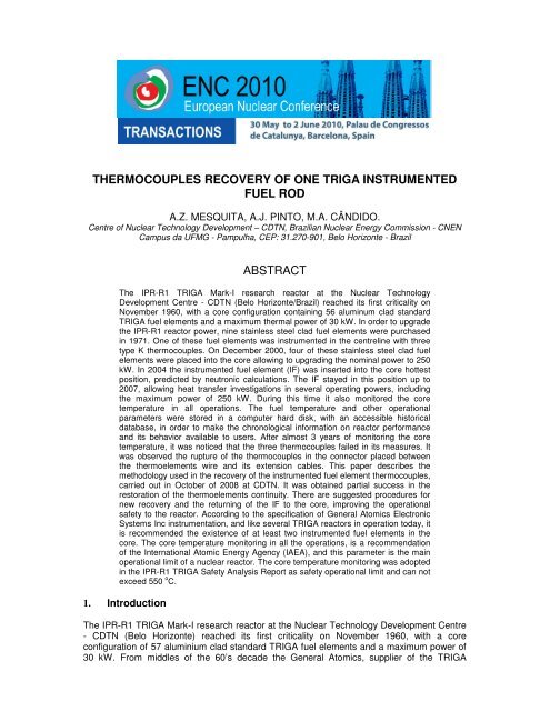
THERMOCOUPLES RECOVERY OF ONE TRIGA INSTRUMENTED<br />
FUEL ROD<br />
A.Z. MESQUITA, A.J. PINTO, M.A. CÂNDIDO.<br />
Centre <strong>of</strong> Nuclear Technology Development – <strong>CDTN</strong>, Brazilian Nuclear Energy Commission - CNEN<br />
Campus da UFMG - Pampulha, CEP: 31.270-901, Belo Horizonte - Brazil<br />
ABSTRACT<br />
The IPR-R1 TRIGA Mark-I research reactor at the Nuclear Technology<br />
Development Centre - <strong>CDTN</strong> (Belo Horizonte/Brazil) reached its first criticality on<br />
November 1960, with a core configuration containing 56 aluminum clad standard<br />
TRIGA <strong>fuel</strong> elements and a maximum thermal power <strong>of</strong> 30 kW. In order to upgrade<br />
the IPR-R1 reactor power, nine stainless steel clad <strong>fuel</strong> elements were purchased<br />
in 1971. One <strong>of</strong> these <strong>fuel</strong> elements was <strong>instrumented</strong> in the centreline with three<br />
type K <strong>thermocouples</strong>. On December 2000, four <strong>of</strong> these stainless steel clad <strong>fuel</strong><br />
elements were placed into the core allowing to upgrading the nominal power to 250<br />
kW. In 2004 the <strong>instrumented</strong> <strong>fuel</strong> element (IF) was inserted into the core hottest<br />
position, predicted by neutronic calculations. The IF stayed in this position up to<br />
2007, allowing heat transfer investigations in several operating powers, including<br />
the maximum power <strong>of</strong> 250 kW. During this time it also monitored the core<br />
temperature in all operations. The <strong>fuel</strong> temperature and other operational<br />
parameters were stored in a computer hard disk, with an accessible historical<br />
database, in order to make the chronological information on reactor performance<br />
and its behavior available to users. After almost 3 years <strong>of</strong> monitoring the core<br />
temperature, it was noticed that the three <strong>thermocouples</strong> failed in its measures. It<br />
was observed the rupture <strong>of</strong> the <strong>thermocouples</strong> in the connector placed between<br />
the thermoelements wire and its extension cables. This paper describes the<br />
methodology used in the <strong>recovery</strong> <strong>of</strong> the <strong>instrumented</strong> <strong>fuel</strong> element <strong>thermocouples</strong>,<br />
carried out in October <strong>of</strong> 2008 at <strong>CDTN</strong>. It was obtained partial success in the<br />
restoration <strong>of</strong> the thermoelements continuity. There are suggested procedures for<br />
new <strong>recovery</strong> and the returning <strong>of</strong> the IF to the core, improving the operational<br />
safety to the reactor. According to the specification <strong>of</strong> General Atomics Electronic<br />
Systems Inc instrumentation, and like several TRIGA reactors in operation today, it<br />
is recommended the existence <strong>of</strong> at least two <strong>instrumented</strong> <strong>fuel</strong> elements in the<br />
core. The core temperature monitoring in all the operations, is a recommendation<br />
<strong>of</strong> the International Atomic Energy Agency (IAEA), and this parameter is the main<br />
operational limit <strong>of</strong> a nuclear reactor. The core temperature monitoring was adopted<br />
in the IPR-R1 TRIGA Safety Analysis Report as safety operational limit and can not<br />
exceed 550 o C.<br />
1. Int<strong>rod</strong>uction<br />
The IPR-R1 TRIGA Mark-I research reactor at the Nuclear Technology Development Centre<br />
- <strong>CDTN</strong> (Belo Horizonte) reached its first criticality on November 1960, with a core<br />
configuration <strong>of</strong> 57 aluminium clad standard TRIGA <strong>fuel</strong> elements and a maximum power <strong>of</strong><br />
30 kW. From middles <strong>of</strong> the 60’s decade the General Atomics, supplier <strong>of</strong> the TRIGA
eactor, doesn't manufacture more aluminum clad <strong>fuel</strong> elements. In order to upgrade the<br />
IPR-R1 reactor power, nine stainless steel clad <strong>fuel</strong> elements were purchased in 1971. One<br />
<strong>of</strong> these <strong>fuel</strong> elements was <strong>instrumented</strong> in the centre line with three type K <strong>thermocouples</strong>.<br />
On December 2000, four <strong>of</strong> these stainless steel clad <strong>fuel</strong> elements were placed into the<br />
core which allowed increasing the nominal reactor power to 250 kW steady state. In 2004<br />
the <strong>instrumented</strong> <strong>fuel</strong> element (IF) was inserted in the core hottest position, predicted by<br />
neutronic calculations. The IF stayed in this position up to 2007, allowing heat transfer<br />
investigations in several operation powers, including in the maximum power <strong>of</strong> 250 kW.<br />
During this time also monitored the core temperature in all operations. The <strong>fuel</strong> temperature<br />
and other operational parameters were stored in a computer hard disk, with an accessible<br />
historical database, in order to make the chronological information on reactor performance<br />
and its behavior available to users. After almost 3 years <strong>of</strong> monitoring the core temperature,<br />
it was noticed that <strong>one</strong> <strong>of</strong> the three <strong>thermocouples</strong> didn't send more the correct value <strong>of</strong> the<br />
measures. Later on, the other two <strong>thermocouples</strong> also failed in its measures. It was<br />
observed the rupture <strong>of</strong> the <strong>thermocouples</strong> in the connector placed between the thermoelements<br />
wire and its extension cables.<br />
The <strong>instrumented</strong> <strong>fuel</strong> element is in all respects identical to standard <strong>fuel</strong> elements, except<br />
that it is equipped with three chromel-alumel <strong>thermocouples</strong> (K type), embedded in the <strong>fuel</strong><br />
meat. The sensitive tips <strong>of</strong> the <strong>thermocouples</strong> are located in the centre <strong>of</strong> the <strong>fuel</strong> element.<br />
Their axial position is <strong>one</strong> at the half-height <strong>of</strong> the <strong>fuel</strong> meat and the other two 2.54 mm<br />
above and 2.54 mm below. The IF was purchased in 1971 and placed in the IPR-R1 core<br />
reactor on 08.18.2004 and stayed in the core until July, 2007. During this time it monitored<br />
the hottest core temperature in all reactor operations and allowed too heat transfer<br />
investigations in the new power operation <strong>of</strong> the reactor <strong>of</strong> 100 kW to 250 kW [1]. After<br />
about 3 years <strong>of</strong> monitoring the core temperature at the core hottest position, the three<br />
<strong>thermocouples</strong> failed in its measures because the rupture in the connector placed between<br />
the <strong>thermocouples</strong> wire and its extension cables (Fig. 2). On August 2007, the <strong>instrumented</strong><br />
<strong>fuel</strong> element was removed from the core and placed in <strong>one</strong> rack located in the reactor tank<br />
inner wall (immersed in the pool water). One year later the IF was removed <strong>of</strong> the TRIGA<br />
pool and put in the well for storage <strong>fuel</strong> irradiated, filled with water, situated in the reactor<br />
room. On October 2008, the IF was raised and started the works the <strong>recovery</strong> the<br />
<strong>thermocouples</strong> continuity. The works had been concluded with partial success on<br />
10.17.2008.<br />
This paper describes the research project in process in <strong>CDTN</strong>, supported by the Fundação<br />
de Amparo à Pesquisa do Estado de Minas Gerais (FAPEMIG) and Conselho Nacional de<br />
Desenvolvimento Científico e Tecnológico (CNPq), that has as objective the <strong>recovery</strong> <strong>of</strong> the<br />
<strong>instrumented</strong> <strong>fuel</strong> element <strong>of</strong> the IPR-R1 TRIGA reactor [2]. The project will improve the<br />
accomplishment <strong>of</strong> neutronic and thermal-hydraulic experiments, foreseen in the <strong>CDTN</strong><br />
research program. The thermocouple tip is in the centre <strong>of</strong> the <strong>fuel</strong> element where the<br />
temperature is normally the highest and with the <strong>instrumented</strong> <strong>fuel</strong> elements inserted in the<br />
locations with maximum power density (the hottest position in the core) provide protection to<br />
reactor and contributes to the installation operational safety. Figure 1 shows the IF before<br />
and after it was been positi<strong>one</strong>d in the IPR-R1 reactor core.
Fig. 1. Instrumented <strong>fuel</strong> element before and after it was been positi<strong>one</strong>d in the IPR-R1<br />
reactor core.<br />
2. Instrumented <strong>fuel</strong> element description and the <strong>thermocouples</strong> breakdown<br />
The TRIGA reactor’s <strong>fuel</strong> element is a cylindrical <strong>rod</strong> with stainless steel (SS-304) cladding.<br />
Its total length is approximately 721 mm with 38.1 mm diameter. Fuel material in each<br />
element is 381 mm long. There are 88.1 mm long cylindrical graphite slugs at the top and<br />
bottom ends, which act as neutron axial reflectors. In the centre <strong>of</strong> the <strong>fuel</strong> material there is a<br />
6.35 mm diameter hole which is filled by a zirconium <strong>rod</strong>. The <strong>fuel</strong> is a homogeneous mixture<br />
<strong>of</strong> uranium and zirconium hydride. Standard stainless steel-clad <strong>fuel</strong> elements with 12 wt %<br />
uranium <strong>of</strong> 20% enrichment (uranium is 20 wt % 235 U). The <strong>instrumented</strong> <strong>fuel</strong> element has<br />
the same nuclear characteristics <strong>of</strong> the normal <strong>fuel</strong> element but posses three <strong>thermocouples</strong><br />
type K (chromel-alumel) <strong>thermocouples</strong> embedded in its zirconium centreline pin. The IF<br />
geometry and dimensions are shown in Fig. 2.<br />
Fig. 2. Instrumented <strong>fuel</strong> element (serial number 6821TC)<br />
Figure 3 shows the place <strong>of</strong> the <strong>thermocouples</strong> breakdown. The <strong>thermocouples</strong> are<br />
manufactured with compacted magnesium oxide (MgO) insulation housed in a stainless steel<br />
sheath with 1.0 mm diameter that protects the thermocouple element from the environment.<br />
The <strong>thermocouples</strong> wires have 0.14 mm <strong>of</strong> diameter [3]. The <strong>thermocouples</strong> leave the<br />
zirconium centreline pin, pass for the graphite reflector, cross the spacer and leave the IF.<br />
Approximately at 10 cm <strong>of</strong> this point exists the connection <strong>of</strong> the chromel-alumel wires and<br />
the extension wires, also made <strong>of</strong> chromel-alumel (detail <strong>of</strong> Fig. 3). The rupture occurred in<br />
this connector as shown in the photograph <strong>of</strong> Figure 4. Analyzing the contact place, it could<br />
be concluded that the thermo-elements wires had been put in contact with two extension<br />
wires without weld and only protected by Epoxy® resin inside <strong>one</strong> potting sleeve <strong>of</strong> plastic
material [4]. Possibly, due to the high nuclear radiation it occured the degradation <strong>of</strong> the<br />
resin and stopped the electrical and mechanical contact between the wires.<br />
Fig. 3. Instrumented <strong>fuel</strong> element and thermocouple connector detail
Fig. 4 . The <strong>thermocouples</strong> and extension cables after the breakdown<br />
3. Instrumented <strong>fuel</strong> burnup calculation results<br />
The results <strong>of</strong> the calculations for characterization <strong>of</strong> the nuclear and thermal parameters <strong>of</strong><br />
the <strong>instrumented</strong> <strong>fuel</strong> element after its withdrawal <strong>of</strong> the core are presented [5]. The<br />
neutronic analyses were performed by using the MCNP (Monte Carlo), ORIGEN and<br />
MONTEBURNS codes, considering the <strong>instrumented</strong> <strong>fuel</strong> in the core hottest position and a<br />
total burnup <strong>of</strong> 100.2 MWh. The simulations results are shown in the Table 1 and Table 2.<br />
The IF had a burnup <strong>of</strong> 0.2 g <strong>of</strong> 235 U (about 0.5%).<br />
The analysis <strong>of</strong> radioactive decay <strong>of</strong> the IF was so strongly conservative, because it was out<br />
all the decay occurred during the time that the IF was in the reactor core. The IF was almost<br />
3 years at the reactor core and only about 42 days <strong>of</strong> irradiation (reactor critical), all the time<br />
remaining was decay, which has been taken out in this analysis. The calculations show that<br />
after 1 year after the IF withdrawal <strong>of</strong> the core, the <strong>fuel</strong> activity was slightly higher than 1 Ci<br />
and the decay heat is less than 1 mW and the parameters <strong>of</strong> radiotoxicity by ingestion and<br />
inhalation are within the expected range.<br />
Tab. 1. Calculated results <strong>of</strong> <strong>instrumented</strong> <strong>fuel</strong> element burnup using the MONTEBURNS<br />
code [5]<br />
Decay after a<br />
235 U Activity Decay Radiotoxicity by Radiotoxicity<br />
burnup <strong>of</strong> 100.2 Mass*<br />
Heat Inhalation by Ingestion<br />
MWh<br />
(Ci)<br />
(month) (g)<br />
(mW)<br />
(m 3 <strong>of</strong> air) (m 3 <strong>of</strong> water)<br />
0 37.8 322.0 886 1.1 x 10 10 1.8 x 10 4<br />
3 37.8 1.7 0.9 1.1 x 10 10 1.8 x 10 4<br />
6 37.8 1.5 0.8 1.1 x 10 10 1.8 x 10 4<br />
9 37.8 1.3 0.7 1.1 x 10 10 1.7 x 10 4<br />
12 37.8 1.1 0.7 1.1 x 10 10 1.7 x 10 4<br />
* started with 38.0 g<br />
In all simulations to calculate the dose rates are disregarded any shield, except that provided<br />
by air at normal temperature and pressure. Two terms <strong>of</strong> radiation sources have been<br />
determined: the first using the term source code generated by the ORIGIN code and a<br />
second, more conservative, in which all the activity calculated for the IF was given the
nuclide Cesium-137 that radiates a unique range <strong>of</strong> 662 keV in its sequence <strong>of</strong><br />
disintegration. The dose rate due to neutrons is negligible in relation to the gamma rays<br />
contribution. The simulations show that the activity after 12 months <strong>of</strong> decay has a very<br />
strong contribution <strong>of</strong> the 137 Cs and 147 Pm fission p<strong>rod</strong>ucts.<br />
Table 2 shows the calculations results <strong>of</strong> dose rates at discharge and after 6 months and 1<br />
year <strong>of</strong> decay. In each situation the doses were calculated at three different points: the<br />
surface (contact with the cladding) in average height <strong>of</strong> the IF, on the surface and shifted 10<br />
cm away from the average height <strong>of</strong> the IF, and 1 meter distance in height. As it was to be<br />
expected, dose rates calculated on all <strong>of</strong> disintegrations <strong>of</strong> Cesium-137 to have more<br />
conservative values.<br />
Tab. 2. Calculated results <strong>of</strong> <strong>instrumented</strong> <strong>fuel</strong> element radioactivity dose rate using the<br />
MCNP code [5]<br />
Method<br />
Decay Time<br />
(months)<br />
At contact in the<br />
IF average<br />
height<br />
Radioactivity dose rate (mRem/h)<br />
At contact and 10<br />
cm distant <strong>of</strong> IF<br />
average height<br />
At 1 m distant <strong>of</strong><br />
the IF average<br />
height<br />
ORIGEN 0 4.4E+05 4.1E+05 5.2E+03<br />
ORIGEN 6 6.8E+03 6.3E+03 8.0E+01<br />
ORIGEN 12 1.3E+03 1.2E+03 1.5E+01<br />
Cesium 137 0 7.9E+06 7.3E+06 9.4E+04<br />
Cesium 137 6 3.7E+04 3.4E+04 4.4E+02<br />
Cesium 137 12 2.7E+04 2.5E+04 3.2E+02<br />
4. Description <strong>of</strong> the <strong>recovery</strong> works<br />
With the <strong>instrumented</strong> <strong>fuel</strong> element located in the well for irradiated <strong>fuel</strong> element storages<br />
(Fig. 5), it was lifted with the aid <strong>of</strong> the manipulation steel handle, in way that only the<br />
terminal part <strong>of</strong> the <strong>thermocouples</strong> was outside the water. Some lead bricks had been placed<br />
for improvement <strong>of</strong> the radiological shield as it can be seen in the photo <strong>of</strong> Figure 6. but in<br />
some places the only shield was the water <strong>of</strong> the well. The radiation level was measured with<br />
a Geiger Counter. In the points where it did not have lead shield the radiation level was <strong>of</strong> 22<br />
mR/h. In the places shielded with lead the radiation level was little above the reactor room<br />
background radiation. The radiation level measured was smaller than the calculated results<br />
shown in Table 2 by the Cesium-137 method, but <strong>of</strong> the same order <strong>of</strong> magnitude by the<br />
ORIGIN method.<br />
Fig. 5. Well for storage <strong>of</strong> irradiated <strong>fuel</strong> element
Fig. 6. Place <strong>of</strong> the rupture <strong>of</strong> the <strong>thermocouples</strong> in the <strong>instrumented</strong> <strong>fuel</strong> element<br />
4.1 Removal <strong>of</strong> the stainless steel shield <strong>of</strong> the <strong>thermocouples</strong><br />
The methodology used for removal <strong>of</strong> the <strong>thermocouples</strong> shield was by an electrical pulse<br />
adjusted to burn only the stainless steel that covering the <strong>thermocouples</strong> [6]. Electrolytic<br />
capacitors had been loaded and its load was used to burn the shield. To find the correct<br />
value <strong>of</strong> electric charge, some preliminary tests with <strong>thermocouples</strong> <strong>of</strong> the same diameter <strong>of</strong><br />
the IF <strong>thermocouples</strong> was used (1.0 mm). It was confecti<strong>one</strong>d two copper elect<strong>rod</strong>es with a<br />
groove <strong>of</strong> 1 mm in order to accommodate the thermocouple before the electric pulse.<br />
After the removal <strong>of</strong> the steel shield, the magnesium oxide (MgO) can be easily removed<br />
with aid <strong>of</strong> a clamp. In this way the two <strong>thermocouples</strong> element wire had been accessible.<br />
Figure 7 shows the assembly used for to remove the <strong>thermocouples</strong> shield.<br />
Fig. 7. Assembly used for removal <strong>of</strong> the <strong>thermocouples</strong> shield by electric charge
4.2 Identification <strong>of</strong> the <strong>thermocouples</strong> wires<br />
The type K <strong>thermocouples</strong> are composites <strong>of</strong> two conductors: the chromel alloy and the<br />
alumel alloy. The chromel is electrically positive and is non-magnetic, already the alumel is<br />
electrically negative and is magnetic. The identification was carried through a small magnetic<br />
piece close to the wires, the <strong>one</strong> that is attracted will be the magnetic wire and the polarity is<br />
negative and it is the alumel alloy. The wires had been kept isolated between themselves<br />
and between them and the shield. Figure 8 shows two <strong>thermocouples</strong> after the metallic<br />
shield and the magnesium oxide has been removed.<br />
Fig. 8. Two <strong>thermocouples</strong> after the shield and the MgO isolation has been removed<br />
4.3 Connection <strong>of</strong> the <strong>thermocouples</strong> wires<br />
After the <strong>thermocouples</strong> wires identification, they were been fixed to the screws <strong>of</strong> the<br />
polarized female half connector (confecti<strong>one</strong>d with chromel or alumel alloy). Epoxy resin<br />
(Araldite <strong>of</strong> normal drying) was placed to help to fix the <strong>thermocouples</strong> wires to the<br />
connector. The other halves <strong>of</strong> the connectors (male) had been connected at to new<br />
extension type K cable. Figure 9 shows the three <strong>thermocouples</strong> already fixed at female half<br />
<strong>of</strong> the connectors, this figure also shown detail <strong>of</strong> the thermocouple connection.<br />
Fig. 9. Thermocouples wires fixed on the connectors
4.4 Quality control<br />
The isolation between <strong>thermocouples</strong> wires and the stainless shield and the continuity <strong>of</strong> the<br />
wires were tested using a digital multimeter. The temperature was measured with the<br />
extension cable connected to <strong>one</strong> digital temperature indicator. Table 3 shows the results.<br />
Thermocouple<br />
Position<br />
Tab. 3. Thermocouples measurements<br />
Wire Electrical<br />
Resistance<br />
[Ω]<br />
Isolation<br />
[Ω]<br />
Temperature<br />
[ o C]<br />
Superior 85.0 22 23.4<br />
Medium 87.4 20 23.6<br />
Inferior 86.1 30 24.2<br />
The <strong>thermocouples</strong> isolation was very lower than new <strong>one</strong> and the wire electrical resistances<br />
(loop continuities) are correct to this <strong>thermocouples</strong> kind and dimensions. The water<br />
temperature was <strong>of</strong> the same magnitude order <strong>of</strong> a calibrated thermocouple that was<br />
inserted in the well. So, it was concluded that the <strong>instrumented</strong> <strong>fuel</strong> element could return to<br />
the reactor core and to monitoring the temperature.<br />
It was made the connection <strong>of</strong> the connector female half (linked to the <strong>thermocouples</strong> wires)<br />
to the male part <strong>of</strong> the connector (linked to the extension cables). Layers <strong>of</strong> silicon rubber<br />
were placed inside and around the connector to mechanical and electrical protection. On the<br />
other day the IF was lowered until the bottom <strong>of</strong> the storage <strong>fuel</strong> irradiated well immersed in<br />
water (3m deep). The <strong>thermocouples</strong> extension cables were connected to the IPR-R1<br />
TRIGA data acquisition system [7]. It was observed that two <strong>of</strong> the three <strong>thermocouples</strong><br />
already more did not indicate correctly the temperature.<br />
5. Conclusion<br />
At the moment only <strong>one</strong> <strong>of</strong> the IF <strong>thermocouples</strong> is working and measuring the water<br />
temperature <strong>of</strong> the <strong>fuel</strong> irradiated storage well, the values are near the surrounding<br />
temperature. The behavior <strong>of</strong> this thermocouple is uncertain if the IF was used to monitoring<br />
the reactor core operational temperatures <strong>of</strong> the order <strong>of</strong> 190 o C, in the reactor operations <strong>of</strong><br />
100 kW (or 300 o C operating in 250 kW). It is recommended to place the IF in a dry local,<br />
with appropriate radiological shield, and did new works to <strong>recovery</strong> the <strong>thermocouples</strong>. The<br />
fission p<strong>rod</strong>ucts decay, present in the <strong>fuel</strong>, will be provide the heat to dry the magnesium<br />
oxide (MgO) used in the isolation between the <strong>thermocouples</strong> wires and between them and<br />
the stainless steel cladding. External source <strong>of</strong> heat like electrical resistor can be used too to<br />
dry the <strong>thermocouples</strong> elements isolation (MgO).<br />
It is emphasized here the importance <strong>of</strong> the presence <strong>of</strong> at least two <strong>instrumented</strong> <strong>fuel</strong><br />
elements in the reactor core as current specification <strong>of</strong> General Atomics Electronic Systems<br />
Inc and the example <strong>of</strong> several existing TRIGA reactor in the world. The IAEA recommends<br />
the monitoring <strong>of</strong> the core temperature in all operations <strong>of</strong> research nuclear reactor [8]. The<br />
<strong>fuel</strong> temperature is the principal operational nuclear reactor variable and there shall be a<br />
system that monitors this parameter and provides a signal that can be utilized in a automatic<br />
mode to prevent the value <strong>of</strong> the temperature from exceeding the safety limit. The <strong>fuel</strong><br />
temperature was adopted in the IPR-R1 TRIGA Safety Analysis Report as safety operational<br />
limit [9]. The <strong>fuel</strong> temperature should not exceed 550 o C. In some operations <strong>of</strong> the IPR-R1<br />
reactor at 250 kW the <strong>fuel</strong> centre temperature in the hottest core position reached 310 °C<br />
[1].
The <strong>instrumented</strong> <strong>fuel</strong> element is the main tool used for operational parameters investigation<br />
in the neutronics and thermal hydraulics experiments performed in IPR-R1 TRIGA reactor. In<br />
addition to recover the actual <strong>instrumented</strong> <strong>fuel</strong> element is recommended the purchase <strong>of</strong> a<br />
new <strong>one</strong>, whose current price is about 80,000 €, as proposed by the manufacturer TRIGA<br />
International [10].<br />
6. Acknowledgments<br />
The authors express their thanks to the Fundação de Amparo à Pesquisa do Estado de<br />
Minas Gerais (FAPEMIG) and to the Conselho Nacional de Desenvolvimento Científico e<br />
Tecnológico (CNPq) for the financial support.<br />
7. References<br />
1. Mesquita, A.Z., “Experimental Investigation on Temperatures Distribuitions in a<br />
Research Nuclear Reactor TRIGA IPR-R1”, Ph.D thesis, Universidade Estadual de<br />
Campinas, São Paulo, Brazil (in Portuguese), (2005).<br />
2. Mesquita. A.Z., "Atualização e Recuperação da Instrumentação do Reator Nuclear de<br />
Pesquisa TRIGA IPR-R1". Edital 03/08. Programa Pesquisador Mineiro II. Projeto de<br />
Pesquisa. Processo FAPEMIG 031-08. (2008).<br />
3. Gulf General Atomic, "Instrumented Fuel Elements Specifications". San Diego.<br />
Califórnia (1971).<br />
4. Gulf General Atomic, "15” SST Fuel Element Assembly Instrumented Core". San Diego.<br />
CA. Drawing Number TOS210J220 (1972).<br />
5. Dalle, H.M, "Simulação da Queima e Determinação de Taxas de Dose para o Elemento<br />
Combustível Instrumentado do Reator TRIGA IPR-R1". Belo Horizonte: CNEN/<strong>CDTN</strong>,<br />
<strong>CDTN</strong> -NI-EC3-01/09 (2009).<br />
6. Mesquita. A.Z.; Ladeira. L.C.D., "Dispositivo para Desencapar Termopares de Isolação<br />
Mineral pela Remoção de sua Blindagem por Corrente Elétrica". Patente de Invenção.<br />
No. 8503430. Depositado no INPI em 08.07 (1985).<br />
7. General Atomics Electronic Systems Inc., "Reactor Instrumentation & Control System<br />
Console for 100 kW IPR-R1 TRIGA Reactor <strong>CDTN</strong> TRIGA ® Reactor Facility at Belo<br />
Horizonte". (GA-ESI) Brazil. July (2008).<br />
7. Mesquita, A.Z. and Rezende, H.C., “Data Acquisition System for TRIGA Mark I Nuclear<br />
Research Reactor <strong>of</strong> <strong>CDTN</strong>”. Proceedings <strong>of</strong> the America Nuclear Energy Symposium<br />
(ANES 2004), Miami Beach, Flórida, USA. America Nuclear Energy (2004).<br />
8. IAEA - International Atomic Energy Agency, "Operational Limits and Conditions <strong>of</strong><br />
Research Reactors". Safety Series No. 35-G6. Vienna (1995).<br />
9. <strong>CDTN</strong>/CNEN, "Safety Analysis Report <strong>of</strong> the IPR-R1 TRIGA Reactor" (RASIN/TRIGA-<br />
IPR-R1/<strong>CDTN</strong>). Belo Horizonte: <strong>CDTN</strong>. (in Portuguese) (2007).<br />
10. TRIGA International, "Supply <strong>of</strong> TRIGA® Fuel Rods". TIFP 001-08. Rev. 1 (Oct 08). 31<br />
CERCA. Lyon. October (2008)