thermocouples recovery of one triga instrumented fuel rod ... - CDTN
thermocouples recovery of one triga instrumented fuel rod ... - CDTN
thermocouples recovery of one triga instrumented fuel rod ... - CDTN

You also want an ePaper? Increase the reach of your titles
YUMPU automatically turns print PDFs into web optimized ePapers that Google loves.
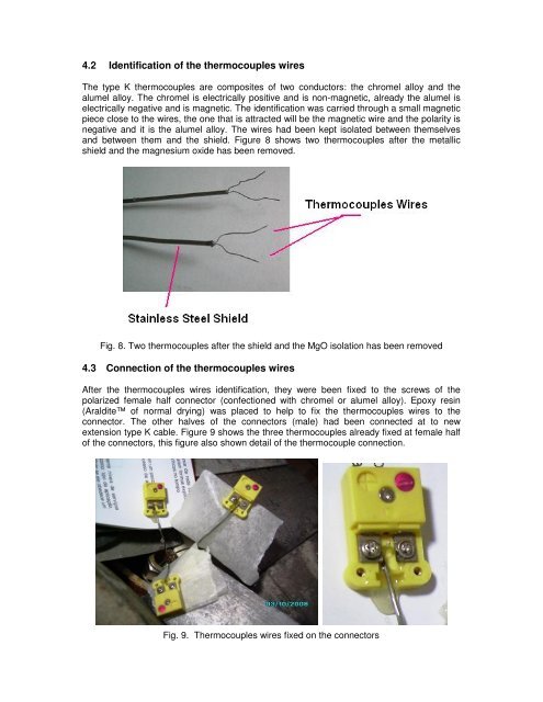
4.2 Identification <strong>of</strong> the <strong>thermocouples</strong> wires<br />
The type K <strong>thermocouples</strong> are composites <strong>of</strong> two conductors: the chromel alloy and the<br />
alumel alloy. The chromel is electrically positive and is non-magnetic, already the alumel is<br />
electrically negative and is magnetic. The identification was carried through a small magnetic<br />
piece close to the wires, the <strong>one</strong> that is attracted will be the magnetic wire and the polarity is<br />
negative and it is the alumel alloy. The wires had been kept isolated between themselves<br />
and between them and the shield. Figure 8 shows two <strong>thermocouples</strong> after the metallic<br />
shield and the magnesium oxide has been removed.<br />
Fig. 8. Two <strong>thermocouples</strong> after the shield and the MgO isolation has been removed<br />
4.3 Connection <strong>of</strong> the <strong>thermocouples</strong> wires<br />
After the <strong>thermocouples</strong> wires identification, they were been fixed to the screws <strong>of</strong> the<br />
polarized female half connector (confecti<strong>one</strong>d with chromel or alumel alloy). Epoxy resin<br />
(Araldite <strong>of</strong> normal drying) was placed to help to fix the <strong>thermocouples</strong> wires to the<br />
connector. The other halves <strong>of</strong> the connectors (male) had been connected at to new<br />
extension type K cable. Figure 9 shows the three <strong>thermocouples</strong> already fixed at female half<br />
<strong>of</strong> the connectors, this figure also shown detail <strong>of</strong> the thermocouple connection.<br />
Fig. 9. Thermocouples wires fixed on the connectors