

Programming Project #3 Texturing a Superquadric Surface
Programming Project #3 Texturing a Superquadric Surface
Programming Project #3 Texturing a Superquadric Surface

Create successful ePaper yourself
Turn your PDF publications into a flip-book with our unique Google optimized e-Paper software.
<strong>Programming</strong> <strong>Project</strong> <strong>#3</strong><br />
<strong>Texturing</strong> a <strong>Superquadric</strong> <strong>Surface</strong><br />
CS 442/542<br />
Due 11:59 pm, November 4, 2013<br />
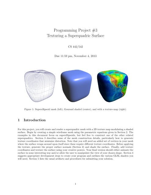
Figure 1: Superellipsoid mesh (left), Gouraud shaded (center), and with a texture-map (right).<br />
1 Introduction<br />
For this project, you will create and render a superquadric mesh with a 2D texture map modulating a shaded<br />
surface. Begin by creating a simple wireframe mesh using the parametric equations given in Section 2. The<br />
examples in this document focus on superellipsoids, but feel free to construct one of the other related<br />
superquadrics. Section 3 describes some of the mesh construction details, particularly how to generate<br />
texture coordinates that minimize distortion. Note that you will need an added set of vertices in your mesh<br />
where the surface wraps around upon itself since these require different texture coordinates. Before applying<br />
the texture, generate the proper surface normals (Section 2) and shade the surface. Finally, add texture<br />
coordinates and texture the surface using your creative powers. Your final version should either animate the<br />
surface in some interesting way and/or allow the user to manipulate the view of your chosen shape. Section 4<br />
suggests appropriate development steps to create your program and outlines the various GLSL shaders you<br />
will need. Section 5 lists the usual artifacts and procedures for submitting your solution.<br />
1
2 <strong>Superquadric</strong> <strong>Surface</strong>s<br />
The surface of superellipsoid can be described parametrically as<br />
for<br />
The parametric equations for a supertoroid are<br />
for<br />
x(u, v) = cos 2/m (v) cos 2/n (u), (1)<br />
y(u, v) = cos 2/m (v) sin 2/n (u), (2)<br />
z(u, v) = sin 2/m (v), (3)<br />
−π/2 ≤ v ≤ π/2, (4)<br />
−π ≤ u ≤ π. (5)<br />
x(u, v) = (d + cos 2/m (v)) cos 2/n (u), (6)<br />
y(u, v) = (d + cos 2/m (v)) sin 2/n (u), (7)<br />
z(u, v) = sin 2/m (v), (8)<br />
−π ≤ v < π (9)<br />
−π ≤ u < π. (10)<br />
The values m and n are called the “bulge factors;” when m = n = 2 the surfaces become their usual quadric<br />
shapes. The surface normal N in both cases is<br />
N x (u, v) = cos 2−2/m (v) cos 2−2/n (u), (11)<br />
N y (u, v) = cos 2−2/m (v) sin 2−2/n (u), (12)<br />
N z (u, v) = sin 2−2/m (v). (13)<br />
It should be noted, that its not legitimate to raise a negative value to a fractional power so expressions like<br />
cos 2/m (v) should be evaluated as cos(v) · | cos(v)| 2/m−1 .<br />
3 Generating a mesh with texture coordinates<br />
Creating a mesh for a parametrically defined surface is fairly straightforward. We simply create a 2D grid of<br />
vertices by sampling the parameters (u, v) across the grid and evaluating the surface’s parametric functions.<br />
Some special care is usually needed at the poles (e.g., for a superellipsoid) and where the surface wraps<br />
around on itself. Here we describe how to create an appropriate mesh for the superellipsoid that we can map<br />
a 2D texture onto.<br />
3.1 Slicing and dicing the surface<br />
We divide up the superellipsoid into N “slices” and M “dices” as illustrated in Figure 2 to create a mesh<br />
with (N + 1) × (M + 1) vertices. We define the surface with N quadrilateral strips with M quadrilaterals<br />
each (the strips run from left to right in the figure). Note the top and bottom strips degenerate into triangles<br />
since the vertices at the poles are all the same point. We don’t use triangle fans at the poles since all the<br />
replicated pole vertices will have different texture coordinates (and we avoid using a different primitive as<br />
a special case). The far-left and far-right columns of vertices represent the same surface points (where the<br />
surface “wraps around on itself”), but will have different texture coordinate s-values.<br />
2
SIDE VIEW<br />
slice 0<br />
slice 1<br />
slice 2<br />
TOP VIEW<br />
dice 1<br />
dice 0<br />
dice M-1<br />
slice N-1<br />
s=0 t=0<br />
u = -π<br />
(N+1)×(M+1) vertices<br />
u = π<br />
N<br />
v = π/2<br />
N-1<br />
t=1<br />
2<br />
1<br />
0<br />
v = -π/2 t=0<br />
0 1 2 M-1 M<br />
Figure 2: The number of vertices in the ellipsoid mesh is specified by the number of “slices” N and “dices”<br />
M used to divide the surface. We use N quadrilateral strips each with M quadrilaterals. The extra column<br />
of vertices are needed where the surface wraps around since different texture coordinates are used on each<br />
end. The top and bottom rows represent the sole vertices at the “poles.”<br />
0 1 2 3 4<br />
5 6 7 8 9<br />
10 11 12 13 14<br />
15 16 17 18 19<br />
20 21 22 23 24<br />
0, 5, 1, 6, 2, 7, 3, 8, 4, 9, 9, 9,<br />
5, 5, 5, 10, 6, 11, 7, 12, 8, 13, 9, 14, 14, 14,<br />
10, 10, 10, 15, 11, 16, 12, 17, 13, 18, 14, 19, 19, 19,<br />
15, 15, 15, 20, 16, 21, 17, 22, 18, 23, 19, 24<br />
Figure 3: These four example quadrilateral strips (defined by black indices) can be converted into a single<br />
quad strip by connecting the strips with degenerate quadrilaterals using the added gray indices.<br />
3
3.2 One big quadrilateral strip<br />
If we are clever, we can represent all N quadrilateral strips with a single strip by adding the appropriate<br />
degenerate quadrilaterals as described in Figure 3. The first and last strips contain 2(M + 1) + 2 vertex<br />
indices whereas all of the middle, non-polar strips have 2(M + 1) + 4 vertex indices; The total number of<br />
indices for the single, unified quadrilateral strip is N(2(M + 1) + 4) − 4.<br />
Figure 4: Bulging mesh with non-uniform distances between vertices (left). Earth texture assuming uniform<br />
spacing (middle) and non-uniform spacing (right).<br />
3.3 Texture coordinates for non-uniformly spaced vertices<br />
If the mesh vertices are distributed uniformly along “latitude” and “longitude” lines (e.g., when bulge factors<br />
are m = n = 2) then we can generate texture coordinates as follows:<br />
(s ij , t ij ) = (i/M, j/N), i = 0, . . . M, j = 0, . . . , M. (14)<br />
The center image in Figure 4 shows the resulting distortion when the vertices are not spaced uniformly. We<br />
avoid the distortion by spacing textures coordinates proportionally based on the Euclidean distance between<br />
successive vertices. Let d i,j be the Euclidian distance between neighboring vertices on the ith line of latitude:<br />
d ij = ‖P i,j − P i,j−1 ‖, j = 1, . . . , M. (15)<br />
Then we space the s-values of our texture coordinates proportional to these distances:<br />
∑ j<br />
k=1<br />
s ij =<br />
d ik<br />
∑ M<br />
k=1 d , i = 1, . . . , N − 1, j = 1, . . . , M, (16)<br />
ik<br />
(s i0 = 0). The s-values at the poles are a special case since these distances are all zero; In these cases we<br />
just copy the values from the adjacent lines of latitude s 0,j = s 1,j and s N,j = s N−1,j for j = 1, . . . , M. We<br />
set the t-values along the lines of longitude in a similar fashion remembering to duplicate these values where<br />
the mesh wraps around on itself: t i,M = t i,0 for i = 1, . . . , N. The right image in Figure 4 shows the proper,<br />
non-distorted texture.<br />
4 Iterative development steps<br />
It is highly recommended that you create your program iteratively. Here I outline the steps I used to for my<br />
program. Each stage will require different GLSL shaders.<br />
4
4.1 Simple wireframe<br />
Your first implementation should focus on creating a wireframe mesh. The only vertex attribute is the<br />
position and the only transformation we need is specified by the ModelView<strong>Project</strong>ion matrix. Here I<br />
“hard code” the vertex color with yellow in my vertex shader:<br />
attribute vec4 vertexPosition;<br />
uniform mat4 ModelView<strong>Project</strong>ion;<br />
varying vec4 color;<br />
void main() {<br />
gl_Position = ModelView<strong>Project</strong>ion*vertexPosition;<br />
color = vec4(1.0, 1.0, 0.0, 1.0);<br />
}<br />
The association fragment shader merely regurgitates the input color:<br />
varying vec4 color;<br />
void main() {<br />
gl_FragColor = color;<br />
}<br />
You will only need VBO’s to store the vertex positions and the quadrilateral indices. Choose a variety of<br />
values for the bulge factors m and n and mesh “slices” and “dices.” Do not proceed until you are confident<br />
this first stage is working correctly. Those developing desktop applications can use glPolygonMode:<br />
glPolygonMode(GL_FRONT_AND_BACK, GL_LINE);<br />
WebGL and OpenGL ES programmers will need to use one of the line primitives (e.g., GL_LINE_LOOP) for<br />
the wireframe version.<br />
4.2 Gouraud shading<br />
Next generate surface normals and replace your vertex shader with one that computes the color at each<br />
vertex via the Phong illumination model. The application will now have to supply the vertex shader with<br />
more information:<br />
attribute vec4 vertexPosition;<br />
attribute vec3 vertexNormal;<br />
uniform mat4 ModelView<strong>Project</strong>ion;<br />
uniform mat4 ModelViewMatrix;<br />
uniform mat3 NormalMatrix;<br />
varying vec4 color;<br />
5
uniform vars for lights & material properties...<br />
...<br />
void main() {<br />
gl_Position = ModelView<strong>Project</strong>ion*vertexPosition;<br />
// compute Phong illumination components<br />
...<br />
color = vec4(I_ambient + I_diffuse + I_specular, 1.0);<br />
}<br />
Again, make sure you are confident that your surface is properly shaded before proceeding to the next<br />
version.<br />
4.3 <strong>Texturing</strong><br />
Figure 5: The TextureMatrix is used to transform the texture coordinates. Scale 4 × 4 (left), scale 8 × 10<br />
(middle), and rotate 45 ◦ and scale 4 × 6 (right).<br />
Next, generate texture coordinates as prescribed in Section 3.3. You will need to load a texture map with<br />
some image – I recommend using a map of the earth. Add another vertex attribute to your vertex shader<br />
for the texture coordinates as well as a TextureMatrix to transform each texture coordinate:<br />
...<br />
attribute vec2 vertexTexCoord;<br />
...<br />
varying vec2 texCoord;<br />
...<br />
uniform mat4 TextureMatrix;<br />
...<br />
void main() {<br />
gl_Position = ModelView<strong>Project</strong>ion*vertexPosition;<br />
texCoord = (TextureMatrix*vec4(vertexTexCoord, 0.0, 1.0)).st;<br />
...<br />
color = vec4(I_ambient + I_diffuse + I_specular, 1.0);<br />
}<br />
The fragment shader now samples the texture map (stored in texture unit 0) and modulates the color.<br />
6
uniform sampler2D texUnit;<br />
varying vec4 color;<br />
varying vec2 texCoord;<br />
void main() {<br />
vec4 texel = texture2D(texUnit, texCoord);<br />
gl_FragColor = texel*color;<br />
}<br />
For your first implementation you may not want to modulate the color, but simply output the texel.<br />
4.3.1 Using the TextureMatrix<br />
Figure 5 illustrates how the TextureMatrix can be used to alter the texture coordinates. For example, the<br />
image of the right was created using the a TextureMatrix set as follows:<br />
matrixIdentity(TextureMatrix);<br />
matrixScale(TextureMatrix, 4, 6, 1);<br />
matrixRotate(TextureMatrix, 45, 0, 0, 1);<br />
Typically we assign texture coordinates to the vertices so that the image covers the entire surface exactly<br />
once; then the TextureMatrix can be used alter the position and size of the texture.<br />
4.3.2 Texture parameters<br />
I set up the texture unit so that the texture to repeats and bilinear interpolation is used for both minification<br />
and magnification:<br />
glTexParameteri(GL_TEXTURE_2D, GL_TEXTURE_WRAP_S, GL_REPEAT);<br />
glTexParameteri(GL_TEXTURE_2D, GL_TEXTURE_WRAP_T, GL_REPEAT);<br />
glTexParameteri(GL_TEXTURE_2D, GL_TEXTURE_MAG_FILTER, GL_LINEAR);<br />
glTexParameteri(GL_TEXTURE_2D, GL_TEXTURE_MIN_FILTER, GL_LINEAR);<br />
4.4 Animating<br />
You may wish to animate changes to your superellipsoid – e.g., rotate and alter than bulge factors m and n<br />
in some interesting way. GLUT allows you to install an idle event callback with the glutIdleFunc() function.<br />
The callback will be invoked whenever other system events are not in the event queue. The callback usually<br />
determines how much time has elapsed and updates the model accordingly:<br />
void idle(void) {<br />
GLfloat seconds = glutGet(GLUT_ELAPSED_TIME)/1000.0;<br />
7
}<br />
/* update object based on elapsed time */<br />
glutPostRedisplay();<br />
If you are constantly changing m and n then the vertices, normals, and texture coordinates are constantly<br />
changing and need to be reloaded into their respective VBO’s. Use the GL_DYNAMIC_DRAW hint when buffering<br />
the data to inform OpenGL that this data is “dynamically” changing and used for “drawing:”<br />
glBindBuffer(GL_ARRAY_BUFFER, vertBuffer);<br />
glBufferData(GL_ARRAY_BUFFER, sizeof(verts), verts, GL_DYNAMIC_DRAW);<br />
5 What to submit<br />
Archive all of your source code and supporting files necessary to build and run your application as described<br />
on the course’s electronic submission web page. Include a README file in your archive that gives an overview<br />
of your project, lists the names of all authors and includes your email address, describes how to build and<br />
run your application from source, and lists all of the files in the archive.<br />
8


![[PDF] Fun with Syntax - ezekiel](https://img.yumpu.com/48148851/1/190x245/pdf-fun-with-syntax-ezekiel.jpg?quality=85)
![[PDF] Syntax and Semantics](https://img.yumpu.com/40036635/1/190x245/pdf-syntax-and-semantics.jpg?quality=85)

![[PDF] Turtle Graphics - ezekiel](https://img.yumpu.com/30626918/1/190x245/pdf-turtle-graphics-ezekiel.jpg?quality=85)
![[PDF] Intro to OpenGL and GLUT programming](https://img.yumpu.com/30459270/1/190x146/pdf-intro-to-opengl-and-glut-programming.jpg?quality=85)
![[PDF] CFL Pumping Lemma](https://img.yumpu.com/29995553/1/190x245/pdf-cfl-pumping-lemma.jpg?quality=85)

![[PDF] Encapsulation + Inheritance + Polymorphism](https://img.yumpu.com/24621947/1/190x245/pdf-encapsulation-inheritance-polymorphism.jpg?quality=85)