


Hierarchical Modeling in OpenGL
Hierarchical Modeling in OpenGL
Hierarchical Modeling in OpenGL

You also want an ePaper? Increase the reach of your titles
YUMPU automatically turns print PDFs into web optimized ePapers that Google loves.
<strong>Hierarchical</strong> <strong>Model<strong>in</strong>g</strong> <strong>in</strong> <strong>OpenGL</strong><br />
CS 442/542<br />
September 4, 2012<br />
1 <strong>Hierarchical</strong> model<strong>in</strong>g and <strong>in</strong>stanc<strong>in</strong>g<br />
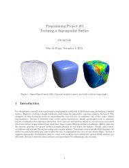
Many objects we wish to model form a natural hierarchy of connected components. “Movement” of<br />
one component causes another set of “attached” components to move <strong>in</strong> like fashion. This hierarchy<br />
can be represented by a tree (more generally a graph) where each child tree <strong>in</strong>herits some set of<br />
transformations (which def<strong>in</strong>e the movement) specified by the parent. For example, consider the<br />
robot arm below. A rotation of θ about the shoulder jo<strong>in</strong>t causes the entire arm to rotate, but a<br />
rotation of φ about the elbow jo<strong>in</strong>t only causes the forearm to move. The forearm <strong>in</strong>herits both<br />
rotations, whereas the biceps <strong>in</strong>herits only the shoulder rotation.<br />
y<br />
y<br />
y<br />
(0,0)<br />
w=2<br />
x<br />
(0,0)<br />
r=1.3<br />
x<br />
r=1<br />
(0,0)<br />
jo<strong>in</strong>t<br />
x<br />
h=6<br />
arm<br />
segment<br />
w=2.4<br />
h=7.2<br />
θ<br />
y<br />
r=1.25<br />
(0,0)<br />
x<br />
φ<br />
w=2.0<br />
h=6.0<br />
1<br />
1.2<br />
1<br />
1/2<br />
r=1.0<br />
1<br />
left f<strong>in</strong>ger<br />
β<br />
β<br />
α<br />
Here we construct our robot arm out of three primitive constructs: a jo<strong>in</strong>t, an arm segment, and<br />
a left f<strong>in</strong>ger. We have conveniently modeled each primitive <strong>in</strong> its own local coord<strong>in</strong>ate system and<br />
have placed the orig<strong>in</strong> at the appropriate “pivot po<strong>in</strong>t.” We use our “jo<strong>in</strong>t template” to create the<br />
shoulder, elbow, and wrist jo<strong>in</strong>ts. This process of creat<strong>in</strong>g multiple shapes from one master shape<br />
is called <strong>in</strong>stanc<strong>in</strong>g and each result<strong>in</strong>g shape is called an <strong>in</strong>stance.<br />
1
2 Scene graph<br />
The follow<strong>in</strong>g tree illustrates how to create our robot’s left arm which is parameterized by three<br />
angles:<br />
• θ : CW rotation about shoulder;<br />
• φ : CCW rotation about elbow;<br />
• α : CCW rotation about wrist;<br />
• β : half-angle of “claw open<strong>in</strong>g.”<br />
left_arm(θ,φ,α,β)<br />
R -θ<br />
S 1.3,1.3<br />
T -7.2,0<br />
S 1.2,1.2<br />
jo<strong>in</strong>t()<br />
forearm(φ,α,β)<br />
arm_segment()<br />
R φ<br />
arm_segment() T -6,0<br />
S 1.25,1.25<br />
claw(α,β)<br />
jo<strong>in</strong>t()<br />
R α<br />
R -β<br />
jo<strong>in</strong>t()<br />
R β<br />
S 1.2,1.2<br />
S 1.2,1.2<br />
left_f<strong>in</strong>ger()<br />
right_f<strong>in</strong>ger()<br />
S -1,1<br />
left_f<strong>in</strong>ger()<br />
Our transformations are composed of rotations (R θ ), scales (S a,b ), and translations (T x,y ). Note<br />
that the robot’s right f<strong>in</strong>ger is made from mirror<strong>in</strong>g the left f<strong>in</strong>ger about the y-axis (i.e., us<strong>in</strong>g a<br />
scale of −1 <strong>in</strong> x). We could use a similar trick to create the robot’s right arm.<br />
The above tree is an example of what is termed a scene graph. Other 3D programm<strong>in</strong>g libraries<br />
are based on a scene graph model (e.g., Java3D).<br />
2
3 Implementation details<br />
3.1 Matrices<br />
Modern <strong>OpenGL</strong> no longer provides “built-<strong>in</strong>” matrices and leaves this up to the program. The<br />
examples below use the follow<strong>in</strong>g “home-brewed” rout<strong>in</strong>es to manipulate matrices stored <strong>in</strong> the<br />
application memory space:<br />
matrixIdentity(GLfloat M[4*4]) Set M to 4 × 4 identity matrix.<br />
matrixScale(GLfloat M[4*4], GLfloat sx, GLfloat sy, GLfloat sz)<br />
Concatenate a scale S matrix onto M (i.e., M ← M · S).<br />
matrixTranslate(GLfloat M[4*4], GLfloat dx, GLfloat dy, GLfloat dz)<br />
Concatenate a translation matrix onto M.<br />
matrixRotate(GLfloat M[4*4], GLfloat theta, GLfloat x, GLfloat y, GLfloat z)<br />
Concatenate a CCW rotation matrix about the vector (x, y, z) onto M (theta is measured <strong>in</strong><br />
degrees).<br />
matrixMultiply(GLfloat M[4*4], const GLfloat A[4*4], const GLfloat B[4*4]);<br />
M ← A · B.<br />
matrixPush(GLfloat M[4*4]); Push matrix M onto <strong>in</strong>ternal stack.<br />
matrixPop(GLfloat M[4*4]); Pop matrix off <strong>in</strong>ternal stack and store <strong>in</strong> M.<br />
We assume that the follow<strong>in</strong>g client matrices are used<br />
GLfloat ModelView[4*4];<br />
GLfloat Projection[4*4];<br />
// composite model<strong>in</strong>g and view matrix<br />
// projection matrix<br />
Before render<strong>in</strong>g any geometry, we construct the composite model-view-projection matrix and load<br />
it <strong>in</strong>to a uniform variable for our vertex shader to use.<br />
GL<strong>in</strong>t ModelViewProjectionUniform; // l<strong>in</strong>k address <strong>in</strong> shader program<br />
...<br />
GLfloat ModelViewProjection[4*4];<br />
matrixMultiply(ModelViewProjection, Projection, ModelView);<br />
glUniformMatrix4fv(ModelViewProjectionUniform, 1, GL_FALSE,<br />
ModelViewProjection);<br />
3
3.2 Articulated arm<br />
Here is an <strong>OpenGL</strong> subrout<strong>in</strong>e that renders the above tree. Note the use of matrixPush and<br />
matrixPop to save and restore the current model-view matrix. The jo<strong>in</strong>t() and arm segment()<br />
rout<strong>in</strong>es implement two of our primitives. The forearm() rout<strong>in</strong>e renders the rema<strong>in</strong><strong>in</strong>g portion<br />
of the tree.<br />
void left_arm(GLfloat theta, GLfloat phi, GLfloat alpha, GLfloat beta) {<br />
matrixPush(ModelView);<br />
matrixRotate(ModelView, -theta, 0, 0, 1);<br />
matrixPush(ModelView);<br />
matrixScale(ModelView, 1.3, 1.3, 1);<br />
jo<strong>in</strong>t();<br />
matrixPop(ModelView);<br />
matrixPush(ModelView);<br />
matrixScale(ModelView, 1.2, 1.2, 1);<br />
arm_segment();<br />
matrixPop(ModelView);<br />
matrixTranslate(ModelView,0, -7.2, 0);<br />
forearm(phi, alpha, beta);<br />
}<br />
matrixPop(ModelView);<br />
3.3 Order is important – last shall be first<br />
Note that the last transformation specified (via matrixScale, matrixRotate, matrixTranslate)<br />
has its effect first – this is critical to represent<strong>in</strong>g our hierarchy. Mathematically, we perform a post<br />
concatenation of the transformation T onto the current model<strong>in</strong>g matrix M yield<strong>in</strong>g MT ; Therefore,<br />
T has its effect before M : (MT )x = M((T )x).<br />
The general form for render<strong>in</strong>g a node <strong>in</strong> the hierarchy often looks like the follow<strong>in</strong>g:<br />
void drawComponent(void) {<br />
matrixPush(ModelView); /* save parent’s model<strong>in</strong>g matrix */<br />
apply global transformations we want children to <strong>in</strong>herit;<br />
for (each child component)<br />
draw child component;<br />
apply local transformations we do *not* want children to <strong>in</strong>herit;<br />
draw other primitives used to model this object;<br />
matrixPop(ModelView); /* restore parent’s model<strong>in</strong>g matrix */<br />
}<br />
4
![[PDF] Fun with Syntax - ezekiel](https://img.yumpu.com/48148851/1/190x245/pdf-fun-with-syntax-ezekiel.jpg?quality=85)
![[PDF] Syntax and Semantics](https://img.yumpu.com/40036635/1/190x245/pdf-syntax-and-semantics.jpg?quality=85)
![[PDF] Turtle Graphics - ezekiel](https://img.yumpu.com/30626918/1/190x245/pdf-turtle-graphics-ezekiel.jpg?quality=85)
![[PDF] Intro to OpenGL and GLUT programming](https://img.yumpu.com/30459270/1/190x146/pdf-intro-to-opengl-and-glut-programming.jpg?quality=85)
![[PDF] CFL Pumping Lemma](https://img.yumpu.com/29995553/1/190x245/pdf-cfl-pumping-lemma.jpg?quality=85)
![[PDF] Encapsulation + Inheritance + Polymorphism](https://img.yumpu.com/24621947/1/190x245/pdf-encapsulation-inheritance-polymorphism.jpg?quality=85)