ABSOLUTE ROTARY ENCODER CAN-BUS
ABSOLUTE ROTARY ENCODER CAN-BUS
ABSOLUTE ROTARY ENCODER CAN-BUS

You also want an ePaper? Increase the reach of your titles
YUMPU automatically turns print PDFs into web optimized ePapers that Google loves.
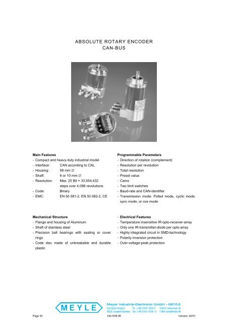
<strong>ABSOLUTE</strong> <strong>ROTARY</strong> <strong>ENCODER</strong><br />
<strong>CAN</strong>-<strong>BUS</strong><br />
Main Features<br />
- Compact and heavy-duty industrial model<br />
- Interface: <strong>CAN</strong> according to CAL<br />
- Housing: 58 mm ∅<br />
- Shaft: 6 or 10 mm ∅<br />
- Resolution: Max. 25 Bit = 33,554,432<br />
steps over 4,096 revolutions<br />
- Code: Binary<br />
- EMC: EN 50 081-2, EN 50 082-2, CE<br />
Programmable Parameters<br />
- Direction of rotation (complement)<br />
- Resolution per revolution<br />
- Total resolution<br />
- Preset value<br />
- Cams<br />
- Two limit switches<br />
- Baud-rate and <strong>CAN</strong>-identifier<br />
- Transmission mode: Polled mode, cyclic mode,<br />
sync mode, or cos mode<br />
Mechanical Structure<br />
- Flange and housing of Aluminum<br />
- Shaft of stainless steel<br />
- Precision ball bearings with sealing or cover<br />
rings<br />
- Code disc made of unbreakable and durable<br />
plastic<br />
- Electrical Features<br />
- Temperature insensitive IR-opto-receiver-array<br />
- Only one IR-transmitter-diode per opto-array<br />
- Highly integrated circuit in SMD-technology<br />
- Polarity inversion protection<br />
- Over-voltage-peak protection<br />
Page 52 Info E58.06 Version: 02/01
<strong>ABSOLUTE</strong> <strong>ROTARY</strong> <strong>ENCODER</strong><br />
<strong>CAN</strong>-<strong>BUS</strong><br />
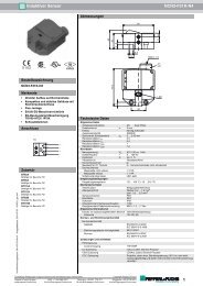
Technical Data<br />
Electrical Data<br />
Supply voltage<br />
10 - 30 V DC (absolute limits)<br />
Power consumption<br />
Max. 3.5 Watt<br />
EMC EN 50081-2, EN 50082-2<br />
Bus connection <strong>CAN</strong> transceiver according to ISO/DIS 11898<br />
Galvanically isolated by opto-couplers<br />
Transmission rate<br />
20 kBaud ... 1 MBaud (programmable)<br />
Accuracy of division<br />
± ½ LSB<br />
Step frequency LSB<br />
Max. 100 kHz (valid code)<br />
Electrical lifetime<br />
> 10 5 h<br />
Node number<br />
Programmable by 2 turn-switches in connection cap<br />
Identifier<br />
Standard 11 bit identifier, passive to 29 bit identifier<br />
Mechanical Data<br />
Housing<br />
Aluminum<br />
Lifetime<br />
> 10 5 h at 1,000 rpm<br />
Inertia of rotor ≈ 50 gcm 2<br />
RPM<br />
Max. 6,000 (continuously)<br />
Shock (IEC 68-2-27) ≤ 200 m/s 2 (12 ms)<br />
Vibration (IEC 68-2-6) ≤ 100 m/s 2 (10 Hz ... 1,000 Hz)<br />
Weight, single-turn<br />
≈ 500 g<br />
Weight, multi-turn<br />
≈ 700 g<br />
Shaft loading<br />
Axial 20 N, radial 110 N<br />
Friction torque<br />
≤ 5 Ncm<br />
Flange Synchro (Y) Clamp (F), synchro (Z)<br />
Shaft diameter 6 mm 10 mm<br />
Shaft length 10 mm 20 mm<br />
Environmental Conditions<br />
Operating temperature 0 ... + 70 °C<br />
Storage temperature - 40 ... + 85 °C<br />
Humidity<br />
98 % (without liquid state)<br />
Protection class (EN 60529)<br />
Casing side IP 65<br />
Shaft side IP 65*<br />
* up to 0.5 bar<br />
Version: 02/01 Info E58.06 Page 53
<strong>ABSOLUTE</strong> <strong>ROTARY</strong> <strong>ENCODER</strong><br />
<strong>CAN</strong>-<strong>BUS</strong><br />
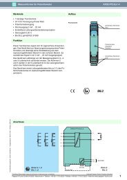
Interface<br />
Installation<br />
The rotary encoder is connected by three cables.<br />
The power supply is achieved with a two-wire<br />
connection cable through one PG 9. Each one of<br />
the twisted-pair and shielded bus lines are guided<br />
in and out through two PG 9 on the right side (as<br />
seen on clamps)<br />
R T<br />
ON<br />
There is a resistor provided in the connection cap,<br />
which must be used as a line termination on the<br />
last device.<br />
Resistor:<br />
21<br />
Last Device<br />
5<br />
7<br />
21<br />
Device X<br />
5<br />
7<br />
+ - G L H G L H<br />
0 0 0<br />
8<br />
7<br />
9<br />
6<br />
5<br />
1<br />
2<br />
4<br />
Bd<br />
3<br />
9<br />
8<br />
7<br />
6<br />
5<br />
1<br />
2<br />
4<br />
x10<br />
3<br />
8<br />
7<br />
9<br />
6<br />
5<br />
1<br />
x1<br />
2<br />
4<br />
3<br />
The setting of the node number is achieved by 2<br />
turn-switches in the connection cap. Possible<br />
addresses lie between 0 and 96 whereby every<br />
address can only be used once. Inside the encoder<br />
the defined address is increased by one. 2 LEDs<br />
on the backside of the connection cap show the<br />
operating status of the encoder.<br />
Clamp<br />
⊥<br />
Description<br />
Ground<br />
+ 24 V Supply voltage<br />
- 0 V Supply voltage<br />
CG <strong>CAN</strong> Ground<br />
CL<br />
<strong>CAN</strong> Low<br />
CH <strong>CAN</strong> High<br />
CG <strong>CAN</strong> Ground<br />
CL<br />
<strong>CAN</strong> Low<br />
CH <strong>CAN</strong> High<br />
Page 54 Info E58.06 Version: 02/01
<strong>ABSOLUTE</strong> <strong>ROTARY</strong> <strong>ENCODER</strong><br />
<strong>CAN</strong>-<strong>BUS</strong><br />
Programmable Encoder - Parameter<br />
Operating Parameters<br />
Resolution per Revolution<br />
Total Resolution<br />
Preset Value<br />
Limit Switch,<br />
Min. and Max.<br />
Cam<br />
As operating parameters the code sequence (complement) can be<br />
programmed. This parameter determines the counting direction, in which the<br />
output code increases or decreases.<br />
The parameter resolution per revolution is used to program the desired<br />
number of steps per revolution. Each value between 1 and 4,096 can be<br />
programmed.<br />
This parameter is used to program the desired number of measuring units<br />
over the total measuring range. This value may not exceed the total<br />
resolution of the absolute rotary encoder. If the encoder is used in a<br />
continuous measuring application, certain rules for the setting of this<br />
parameter must be followed. These rules are outlined in the manual.<br />
The preset value is the desired position value, which should be reached at a<br />
certain physical position of the axis. The position value is set to the desired<br />
process value by the parameter pre-set.<br />
Two position values can be programmed as limit switches. By reaching<br />
these values one bit of the 32 bit process value is set to high.<br />
One free programmable cam can be set in the total measaring range. The<br />
same functionality is realised like a mechanical cam unit.<br />
Programmable <strong>CAN</strong> Transmission Modes<br />
Polled Mode<br />
Cyclic Mode<br />
Sync Mode<br />
By a remote-transmission-request telegram the connected host calls for the<br />
current process value. The absolute rotary encoder reads the current<br />
position value, calculates eventually set-parameters and sends back the<br />
obtained process value by the same identifier.<br />
The absolute rotary encoder transmits cyclically - without being called by the<br />
host - the current process value. The cycle time can be programmed in<br />
milliseconds for values between 1 ms and 65536 ms.<br />
After receiving a sync telegram by the host, the absolute rotary encoder<br />
answers with the current process value. If more than one node number<br />
(encoder) shall answer after receiving a sync telegram, the answer<br />
telegrams of the nodes will be received by the host in order of their node<br />
numbers. The programming of an offset-time is not necessary. If a node<br />
should not answer after each sync telegram on the <strong>CAN</strong> network, the<br />
parameter sync counter can be programmed to skip a certain number of<br />
sync telegrams before answering again.<br />
Version: 02/01 Info E58.06 Page 55
<strong>ABSOLUTE</strong> <strong>ROTARY</strong> <strong>ENCODER</strong><br />
<strong>CAN</strong>-<strong>BUS</strong><br />
Mechanical Drawings<br />
Synchro Flange (Y,Z)<br />
The only difference between the Y- and Z-Flange<br />
is the shaft size (refer to the table besides).<br />
d [mm] l [mm]<br />
Y-Flange 6 f6 10<br />
Z-Flange 10 h8 20<br />
Single-Turn=83, Multi-Turn=109<br />
30<br />
M4x8<br />
3x120°<br />
ø58<br />
f7<br />
ø50<br />
d<br />
Ø59<br />
23<br />
66<br />
Ø60<br />
Ø42<br />
l<br />
3<br />
~32<br />
3<br />
4<br />
15<br />
Clamp Flange (F)<br />
30<br />
Single-Turn=83, Multi-Turn=109<br />
M4x8<br />
30<br />
10<br />
3x120°<br />
Ø58<br />
Ø52<br />
f7<br />
Ø36<br />
Ø10 h8<br />
1<br />
18<br />
Ø59<br />
23<br />
66<br />
Ø60<br />
Ø48<br />
3<br />
3<br />
~32<br />
15<br />
Page 56 Info E58.06 Version: 02/01
<strong>ABSOLUTE</strong> <strong>ROTARY</strong> <strong>ENCODER</strong><br />
<strong>CAN</strong>-<strong>BUS</strong><br />
Connection cap with 5pin round connector, Micro style<br />
30<br />
23<br />
66<br />
20<br />
Ø60<br />
15<br />
12<br />
Version: 02/01 Info E58.06 Page 57
<strong>ABSOLUTE</strong> <strong>ROTARY</strong> <strong>ENCODER</strong><br />
<strong>CAN</strong>-<strong>BUS</strong><br />
Models/Ordering Description<br />
Description<br />
Type Key<br />
Absolute rotary encoder AWC 58 . . - . . . . - . B B1<br />
Diameter in mm<br />
Steps per revolution 4096 12<br />
8192 13<br />
No. Of revolutions 1 1<br />
4096 4096<br />
Flange<br />
Clamp Flange (Shaft = 10 mm ∅) F<br />
Synchro Flange (Shaft = 6 mm ∅) Y<br />
Synchro Flange (Shaft = 10 mm ∅) Z<br />
Code Binary B<br />
Version<br />
Interface<br />
Options<br />
<strong>CAN</strong> non programmable C1<br />
programmable<br />
without connection cap *1) C5<br />
Without 0<br />
Shaft sealing (not possible for Z-Flange)<br />
W<br />
Stainless steel configuration (flange, housing, cap)<br />
Connection 3 PG-exits, radial at connection cap *2) 3PG<br />
Cable-exit (only for interface C5)<br />
00R<br />
*1) Configuration of baudrate and node number via SDO-objects is only available with cable-exit.<br />
*2) The connection cap has to be ordered separately !<br />
Zubehör und Dokumentation<br />
B1<br />
C2<br />
Q<br />
Description<br />
Type<br />
Connection cap*2) T-coupling-functionality with integrated address<br />
setting is necessary to use the encoder<br />
Standard<br />
AH 58B1-CA-3PG<br />
Stainless steel configuration<br />
AH 58B1-CA-3PG-VA<br />
Connection with 5pin round connector, Micro style AH 58B1-CA-1BW<br />
Shaft coupling<br />
Drilling: 10 mm GS 10<br />
Drilling:: 6 mm GS 06<br />
Clamp disc 4 pcs. / AWC SP 15<br />
Clamp ring 2 pcs. / AWC SP H<br />
User Manual*3) Installation and configuration manual, German UMD-CA<br />
User Manual*3) Installation and configuration manual, English UME-CA<br />
EDS-File*3) Disc containing EDS-file for coniguration. DK-CA<br />
*3) These can be downloaded free of charge from our Homepage www.meyle.de .<br />
We do not assume responsibility for technical inaccuracies or omissions. Specifications are subject to<br />
change without notice.<br />
Page 58 Info E58.06 Version: 02/01