hole plugging of liquid photoimageable solder masks - Coates Screen
hole plugging of liquid photoimageable solder masks - Coates Screen
hole plugging of liquid photoimageable solder masks - Coates Screen

Create successful ePaper yourself
Turn your PDF publications into a flip-book with our unique Google optimized e-Paper software.
<strong>hole</strong> <strong>plugging</strong> <strong>of</strong> <strong>liquid</strong><br />
<strong>photoimageable</strong> <strong>solder</strong> <strong>masks</strong><br />
by Gerson Vas – Development Manager, <strong>Coates</strong> Circuit Products<br />
PROCESSES CURRENTLY BEING USED BY<br />
FABRICATORS<br />
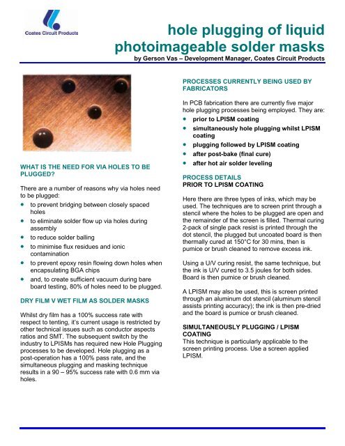
WHAT IS THE NEED FOR VIA HOLES TO BE<br />
PLUGGED?<br />
There are a number <strong>of</strong> reasons why via <strong>hole</strong>s need<br />
to be plugged:<br />
• to prevent bridging between closely spaced<br />
<strong>hole</strong>s<br />
• to eliminate <strong>solder</strong> flow up via <strong>hole</strong>s during<br />
assembly<br />
• to reduce <strong>solder</strong> balling<br />
• to minimise flux residues and ionic<br />
contamination<br />
• to prevent epoxy resin flowing down <strong>hole</strong>s when<br />
encapsulating BGA chips<br />
• and, to create sufficient vacuum during bare<br />
board testing, 80% <strong>of</strong> <strong>hole</strong>s need to be plugged.<br />
DRY FILM V WET FILM AS SOLDER MASKS<br />
Whilst dry film has a 100% success rate with<br />
respect to tenting, it’s current usage is restricted by<br />
other technical issues such as conductor aspects<br />
ratios and SMT. The subsequent switch by the<br />
industry to LPISMs has required new Hole Plugging<br />
processes to be developed. Hole <strong>plugging</strong> as a<br />
post-operation has a 100% pass rate, and the<br />
simultaneous <strong>plugging</strong> and masking technique<br />
results in a 90 – 95% success rate with 0.6 mm via<br />
<strong>hole</strong>s.<br />
In PCB fabrication there are currently five major<br />
<strong>hole</strong> <strong>plugging</strong> processes being employed. They are:<br />
• prior to LPISM coating<br />
• simultaneously <strong>hole</strong> <strong>plugging</strong> whilst LPISM<br />
coating<br />
• <strong>plugging</strong> followed by LPISM coating<br />
• after post-bake (final cure)<br />
• after hot air <strong>solder</strong> leveling<br />
PROCESS DETAILS<br />
PRIOR TO LPISM COATING<br />
Here there are three types <strong>of</strong> inks, which may be<br />
used. The techniques are to screen print through a<br />
stencil where the <strong>hole</strong>s to be plugged are open and<br />
the remainder <strong>of</strong> the screen is filled. Thermal curing<br />
2-pack <strong>of</strong> single pack resist is printed through the<br />
dot stencil, the plugged but uncoated board is then<br />
thermally cured at 150°C for 30 mins, then is<br />
pumice or brush cleaned to remove excess ink.<br />
Using a U/V curing resist, the same technique, but<br />
the ink is U/V cured to 3.5 joules for both sides.<br />
Board is then pumice or brush cleaned.<br />
A LPISM may also be used, this is screen printed<br />
through an aluminum dot stencil (aluminum stencil<br />
assists printing accuracy); the ink is then pre-dried<br />
and the board is pumice or brush cleaned.<br />
SIMULTANEOUSLY PLUGGING / LPISM<br />
COATING<br />
This technique is particularly applicable to the<br />
screen printing process. Use a screen applied<br />
LPISM.
Double print the first side through a dot stencil with<br />
a 43T mesh Single print the second side as above,<br />
but with a different squeegee pressure to ensure<br />
that the <strong>hole</strong>s are plugged. Process as normal for a<br />
screen applied LPISM, but the post-bake (final<br />
cure) cycle should be staged – 20 minutes @<br />
100°C, then 60 minutes @ 150°C.<br />
PLUGGING, FOLLOWED BY LPISM COATING<br />
The uncoated board is screen printed through an<br />
aluminum dot stencil mesh, ensuring that the <strong>hole</strong>s<br />
are plugged, but not overfilled. Registration needs<br />
to be accurate, or de-lamination and blistering may<br />
occur.<br />
The first side <strong>of</strong> the board is then curtain / spray<br />
coated and pre-dried.<br />
The second side <strong>of</strong> the board is curtain / spray<br />
coated and pre-dried.<br />
The board is then processed as normal using<br />
existing parameters for exposure and development.<br />
Post-Bake in a conveyorised oven – set line for 11<br />
zones, with a dwell time <strong>of</strong> 9 minutes in each zone.<br />
1 st zone @ 85°C, 2 nd zone @ 95°C, 3 rd zone @<br />
105°C, 4 th zone @ 115°C, 5 th zone @ 135°C, then<br />
the remaining 6 zones @ 155°C. Post-Bake<br />
conditions should be optimised at each fabricator.<br />
PRODUCTS CURRENTLY AVAILABLE<br />
Listed below are specific products currently<br />
available from <strong>Coates</strong> for the processes described<br />
above.<br />
products currently available<br />
PRODUCT<br />
100% Solids U/V<br />
Curing Resist<br />
2-pack Thermal<br />
Curing Resist<br />
Liquid<br />
Photoimageable<br />
Solder Mask<br />
Imagecure ®<br />
SALES<br />
REFERENCE<br />
XV1200 Clear<br />
XZ15HP Resist<br />
XZ17B Hardener<br />
XV501TPH<br />
Resist<br />
XV501TPH<br />
Hardener<br />
PACK CODE<br />
CFSN 6030<br />
CKXN 0165<br />
CCSN 3010<br />
CKXN 0150<br />
CKXN 0151<br />
FUTURE DEVLOPMENTS<br />
There is little doubt that the demand for <strong>hole</strong><br />
<strong>plugging</strong> processes will continue to increase. We<br />
are happy to say that our current screen-printing<br />
and curtain coating products work extremely well,<br />
and customers are welcome to discuss their<br />
requirements with us at any time.<br />
AFTER POST BAKE<br />
Here the board can be retro-plugged, using either a<br />
100% solids UV curing resist, thermal single or twopack<br />
resists, or, where planarity on BGA chips is an<br />
issue, use LPISM. Processes as per (a) above<br />
omitting brush or pumice clean. Panels after predry<br />
need to be developed, to remove excess ink,<br />
prior to final post-bake.<br />
AFTER HASL<br />
As after Post Bake but do not use LPISM<br />
For more information contact:<br />
<strong>Coates</strong> Circuit Products<br />
Norton Hill<br />
Midsomer Norton<br />
Bath BA3 4RT United Kingdom<br />
(44) 01761-414471 Phone<br />
(44) 01761-417446 Fax