AVS24-MFT2 linear actuator for S6... control valves - - Belimo
AVS24-MFT2 linear actuator for S6... control valves - - Belimo
AVS24-MFT2 linear actuator for S6... control valves - - Belimo

Create successful ePaper yourself
Turn your PDF publications into a flip-book with our unique Google optimized e-Paper software.
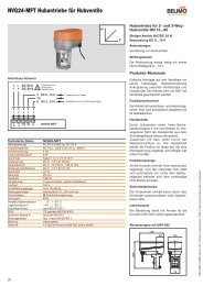
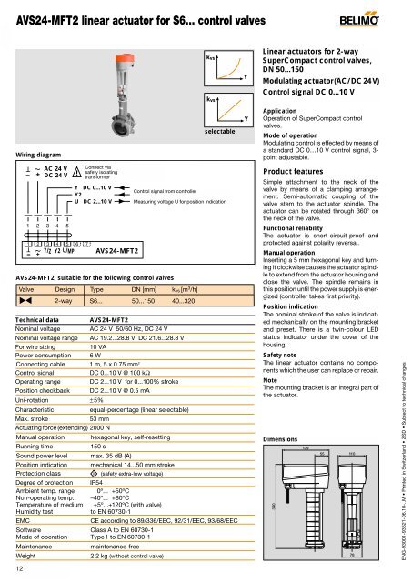
<strong>AVS24</strong>-<strong>MFT2</strong> <strong>linear</strong> <strong>actuator</strong> <strong>for</strong> <strong>S6.</strong>.. <strong>control</strong> <strong>valves</strong><br />
kvs<br />
kvs<br />
Y<br />
Linear <strong>actuator</strong>s <strong>for</strong> 2-way<br />
SuperCompact <strong>control</strong> <strong>valves</strong>,<br />
DN 50...150<br />
Modulating <strong>actuator</strong>(AC/DC 24V)<br />
Control signal DC 0...10 V<br />
Wiring diagram<br />
selectable<br />
Y<br />
Application<br />
Operation of SuperCompact <strong>control</strong><br />
<strong>valves</strong>.<br />
Mode of operation<br />
Modulating <strong>control</strong> is effected by means of<br />
a standard DC 0…10 V <strong>control</strong> signal, 3-<br />
point adjustable.<br />
-<br />
T<br />
AC 24 V<br />
+ DC 24 V<br />
~<br />
1 2 3 4 5<br />
T1 2 3<br />
- + Y/Z<br />
~<br />
4<br />
Y2<br />
5<br />
U/MP<br />
!<br />
Y DC 0...10 V<br />
Y2<br />
U DC 2...10 V<br />
6 7<br />
Connect via<br />
safety isolating<br />
trans<strong>for</strong>mer<br />
<strong>AVS24</strong>-<strong>MFT2</strong><br />
Control signal from <strong>control</strong>ler<br />
Measuring voltage U <strong>for</strong> position indication<br />
<strong>AVS24</strong>-<strong>MFT2</strong>, suitable <strong>for</strong> the following <strong>control</strong> <strong>valves</strong><br />
Valve Design Type DN [mm] k vs [m 3 /h]<br />
2-way <strong>S6.</strong>.. 50...150 40...320<br />
Technical data<br />
Nominal voltage<br />
<strong>AVS24</strong>-<strong>MFT2</strong><br />
AC 24 V 50/60 Hz, DC 24 V<br />
Nominal voltage range AC 19.2...28.8 V, DC 21.6...28.8 V<br />
For wire sizing<br />
10 VA<br />
Power consumption 6 W<br />
Connecting cable 1 m, 5 x 0.75 mm 2<br />
Control signal<br />
DC 0...10 V @ 100 kΩ<br />
Operating range DC 2...10 V <strong>for</strong> 0...100% stroke<br />
Position checkback DC 2...10 V @ 0.5 mA<br />
Uni-rotation ±5%<br />
Characteristic<br />
Max. stroke<br />
53 mm<br />
Actuating <strong>for</strong>ce (extending) 2000 N<br />
Manual operation<br />
Running time<br />
Sound power level<br />
Position indication<br />
Protection class<br />
EMC<br />
Maintenance<br />
hexagonal key, self-resetting<br />
150 s<br />
max. 35 dB (A)<br />
mechanical 14...50 mm stroke<br />
(safety extra-low voltage)<br />
Degree of protection IP54<br />
Ambient temp. range 0º... +50ºC<br />
Non-operating temp. –40º... +80ºC<br />
Temperature of medium +5º...+120ºC (with valve)<br />
Humidity test to EN 60730-1<br />
Software Class A to EN 60730-1<br />
Mode of operation Type1 to EN 60730-1<br />
Weight<br />
equal-percentage (<strong>linear</strong> selectable)<br />
III<br />
CE according to 89/336/EEC, 92/31/EEC, 93/68/EEC<br />
maintenance-free<br />
2.2 kg (without <strong>control</strong> valve)<br />
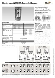
Product features<br />
Simple attachment to the neck of the<br />
valve by means of a clamping arrangement.<br />
Semi-automatic coupling of the<br />
valve stem to the <strong>actuator</strong> spindle. The<br />
<strong>actuator</strong> can be rotated through 360° on<br />
the neck of the valve.<br />
Functional reliability<br />
The <strong>actuator</strong> is short-circuit-proof and<br />
protected against polarity reversal.<br />
Manual operation<br />
Inserting a 5 mm hexagonal key and turning<br />
it clockwise causes the <strong>actuator</strong> spindle<br />
to extend from the <strong>actuator</strong> housing and<br />
close the valve. The spindle remains in<br />
this position until the power supply is energized<br />
(<strong>control</strong>ler takes first priority).<br />
Position indication<br />
The nominal stroke of the valve is indicated<br />
mechanically on the mounting bracket<br />
and preset. There is a twin-colour LED<br />
status indicator under the cover of the<br />
housing.<br />
Safety note<br />
The <strong>linear</strong> <strong>actuator</strong> contains no components<br />
which the user can replace or repair.<br />
Note<br />
The mounting bracket is an integral part of<br />
the <strong>actuator</strong>.<br />
Dimensions<br />
340<br />
179<br />
55<br />
110<br />
78<br />
ENG-93001-93621-06.10-..M • Printed in Switzerland • ZSD • Subject to technical changes<br />
12
<strong>AVS24</strong>-<strong>MFT2</strong> <strong>linear</strong> <strong>actuator</strong> <strong>for</strong> <strong>S6.</strong>.. <strong>control</strong> <strong>valves</strong><br />
Arrangement of the operating <strong>control</strong>s<br />
M<br />
H1 S1 S3.1<br />
Symbol<br />
S2<br />
H<br />
1 2 3 4 5<br />
T<br />
–<br />
~<br />
+<br />
Y/Z Y2 U/MP<br />
ON<br />
6 7<br />
S3<br />
1 2<br />
1<br />
ON 1 2<br />
S3.2<br />
ON<br />
2<br />
H<br />
Y<br />
Y<br />
Symbol<br />
kvs<br />
kvs<br />
Y<br />
Y<br />
Under the cover of the <strong>actuator</strong> are the terminals<br />
<strong>for</strong> connecting the lead, the <strong>control</strong><br />
devices S1, S2 and S3 and the LED indicator<br />
H1.<br />
By setting the slide switch S3 appropriately<br />
or by pressing push-buttons S1 and S2<br />
it is possible to configure the <strong>actuator</strong> very<br />
simply on-site to suit actual requirements<br />
when changes from the factory settings<br />
are needed.<br />
Note<br />
With the AV.. <strong>MFT2</strong> types, slide switch<br />
S3.2 is the valve closing point. The closing<br />
point of the SuperCompact <strong>control</strong><br />
valve is in the down position which is the<br />
standard <strong>for</strong> the AVS <strong>actuator</strong> and cannot<br />
be changed.<br />
Functional description S<br />
Function<br />
Test<br />
Init<br />
(Adaption)<br />
Description<br />
The valve covers the full stroke in maximum running time and<br />
verifies the adapted stroke to ensure that both end-points are<br />
reached (H = 0% and H = 100%).<br />
The parameterized stroke is pre-programmed in the <strong>linear</strong> <strong>actuator</strong><br />
(parameterized stroke = Nominal stroke in function DN, see Page 8).<br />
When the adaption button S2 is pressed the <strong>actuator</strong> moves upward<br />
from the closing point (down) by the amount of the parameterized<br />
stroke and per<strong>for</strong>ms synchronization. At the same time the <strong>control</strong><br />
signal and the running time are adapted to this parameterized stroke.<br />
Switch<br />
S1<br />
press<br />
S2<br />
press<br />
Direction of stroke The direction of travel in response to the <strong>control</strong> signal<br />
S3.1<br />
Direct 0% <strong>control</strong> signal corresponds to 0% position checkback.<br />
OFF<br />
(The <strong>actuator</strong> spindle is extended)<br />
Symbol<br />
H<br />
Bold type in the<br />
table means<br />
standard factory<br />
setting.<br />
Y<br />
Inverted<br />
(Reverse)<br />
0% <strong>control</strong> signal corresponds to 100% position checkback.<br />
(The <strong>actuator</strong> spindle is retracted)<br />
ON<br />
H<br />
ENG-93001-93621-06.10-..M • Printed in Switzerland • ZSD • Subject to technical changes<br />
Valve<br />
characteristic<br />
Equalpercentage<br />
Linear<br />
Only properly authorized and trained persons may change the settings of slide switch S3 and push-button S2.<br />
LED indicator H1<br />
Green steady light<br />
Green flashing light<br />
Red steady light<br />
Red flashing light<br />
Alternate red /<br />
green flashing light<br />
Function of the <strong>control</strong> signal S3.2<br />
With the S6 valve the water flow has an equal-percentage<br />
relationship with the <strong>control</strong> signal<br />
With the S6 valve the water flow has a <strong>linear</strong> relationship with the<br />
<strong>control</strong> signal<br />
Actuator working properly<br />
Test run or adaptation with synchronization in progress<br />
Fault; repeat adaptation<br />
After power interruption (> 2 sec.). By the next closing movement<br />
the valve will be automatically synchronized in the<br />
chosen closing point. The LED indicator will change from a<br />
red flashing into a green steady light.<br />
Addressing via <strong>control</strong> system and operation of adaptation<br />
push-button S2 in progress<br />
Note:<br />
Tables MFT and Remote <strong>control</strong> with Multi-Point communication (MP), see Page 14<br />
OFF<br />
ON<br />
Symbol<br />
kvs<br />
kvs<br />
The <strong>actuator</strong> is maintenance-free. The<br />
twin-colour LED indicator is under the<br />
cover of the <strong>actuator</strong>; the indicator shows<br />
actual <strong>actuator</strong> status. It also allows simple<br />
commissioning if the factory settings<br />
need to be changed.<br />
Y<br />
Y<br />
Y<br />
13
NVS24../<strong>AVS24</strong>.. <strong>linear</strong> <strong>actuator</strong>s <strong>for</strong> <strong>S6.</strong>.. <strong>control</strong> <strong>valves</strong><br />
Motion of the <strong>actuator</strong> spindle<br />
Feedback U5 with configured modulating <strong>linear</strong> <strong>actuator</strong><br />
-<br />
~ T<br />
AC 24 V<br />
+ DC 24 V<br />
1 2 3 4 5<br />
!<br />
Connect via<br />
safety isolating<br />
trans<strong>for</strong>mer<br />
Y DC<br />
Control signal from <strong>control</strong>ler<br />
U DC<br />
Measuring voltage <strong>for</strong><br />
position indicaton<br />
Slide switch<br />
Control position Measuring Spindle Valve S6<br />
signal S3.1 S3.2 voltage<br />
10 V Off 10 V retracting 100%<br />
On 2 V extending 0%<br />
2 V Off 2 V extending 0%<br />
On 10 V retracting 100%<br />
Switch position S3.2 has no effect on the direction of travel of the <strong>actuator</strong><br />
spindle.<br />
Bold type in the<br />
table means<br />
standard factory<br />
setting.<br />
1 2 3<br />
- + Y/Z<br />
T<br />
~<br />
4<br />
Y2<br />
5 6 7<br />
NVS24-MFT(2)<br />
U/MP <strong>AVS24</strong>-<strong>MFT2</strong><br />
Override <strong>control</strong> «Open»<br />
AC 24 V<br />
- + DC 24 V<br />
T<br />
~<br />
1 2<br />
a<br />
b<br />
3 4 5<br />
!<br />
Connect via<br />
safety isolating<br />
trans<strong>for</strong>mer<br />
Y (DC 0...10 V)<br />
from <strong>control</strong>ler<br />
Slide switch<br />
position<br />
Relay contact Linear <strong>actuator</strong> Valve S6<br />
a b Linear<br />
S3.1 S3.2 Spindle<br />
Off Closed Open retracting 100%<br />
On Closed Open extending 0%<br />
Switch position S3.2 has no effect on the direction of travel of<br />
the <strong>actuator</strong> spindle<br />
1 2 3 4 5<br />
~ T<br />
–<br />
+<br />
Y/Z Y2 U/MP<br />
6 7<br />
NVS24-MFT(2)<br />
<strong>AVS24</strong>-<strong>MFT2</strong><br />
3-point <strong>control</strong><br />
14<br />
!<br />
AC 24 V<br />
- + DC 24 V<br />
- + Y/Z Y2 U/MP<br />
a b<br />
1 2 3 4 5<br />
1 2 3 4 5<br />
T<br />
~<br />
~ T<br />
MFT<br />
6 7<br />
Connect via<br />
safety isolating<br />
trans<strong>for</strong>mer<br />
NVS24-MFT(2)<br />
<strong>AVS24</strong>-<strong>MFT2</strong><br />
Slide switch<br />
position<br />
In 3-point mode there is a time delay of approx. 1 s after the<br />
<strong>control</strong> contacts meet be<strong>for</strong>e the <strong>actuator</strong> spindle moves.<br />
Parameter Standard Variable<br />
Positioning signal DC 0...10 V 3-point*, Open/Closed<br />
Operating range DC 2...10 V Start point DC 0.5...30 V<br />
End point DC 0.5...30 V<br />
Position feedback DC 2...10 V Start point DC 0.5...30 V<br />
U 5<br />
End point DC 0.5...30 V<br />
Changeover to fault alarm<br />
Running time 150 s NVS24-MFT(2): (35)75...300 s 1)<br />
<strong>AVS24</strong>-<strong>MFT2</strong>: (75)150...300 s 2)<br />
Actuating <strong>for</strong>ce 100% 50...100%<br />
1) 35 s only with 10 mm stroke 2) 75 s only with 20 mm stroke<br />
Remote <strong>control</strong> with Multi-Point communication<br />
Relay contact Linear <strong>actuator</strong> Valve S6<br />
a b Spindle<br />
S3.1<br />
Off Open Open stopping stopped<br />
Off Closed Open retracting opening<br />
Off Open Closed extending closing<br />
On Open Open stopping stopped<br />
On Closed Open retracting closing<br />
On Open Open extending opening<br />
Remote <strong>control</strong> With Multi-Point communication the <strong>actuator</strong> can be operated<br />
by remote <strong>control</strong>.<br />
Fault alarm When the SW flag has been set a signal <strong>for</strong> U 5 checkback is<br />
also available in addition to the LED status indicator.<br />
MP communication The <strong>actuator</strong> is prepared <strong>for</strong> room bus operation.<br />
Up to 8 <strong>actuator</strong>s can be wired in parallel.<br />
!<br />
Not allowed with the<br />
equal-percentage<br />
characteristic.<br />
Slide switch S3.2 must<br />
be in the ON position<br />
(<strong>linear</strong>).<br />
Multi-Function Technology allows optimum<br />
matching of parameters to the different<br />
needs of an installation. The parameters<br />
are either entered as standard<br />
values at the factory or altered subsequently<br />
using an MFT-H adjuster.<br />
Bold type in the table means standard<br />
factory setting.<br />
*3-point is only allowed when S3.2 is set to the<br />
ON position (<strong>linear</strong>).<br />
Instead of an analogue measuring voltage<br />
it is also possible to read and write digital<br />
data at the U 5 connecting terminal using a<br />
suitable interface.<br />
ENG-93001-93621-06.10-..M • Printed in Switzerland • ZSD • Subject to technical changes