322055-000 - AO Smith Water Heaters
322055-000 - AO Smith Water Heaters
322055-000 - AO Smith Water Heaters
Create successful ePaper yourself
Turn your PDF publications into a flip-book with our unique Google optimized e-Paper software.
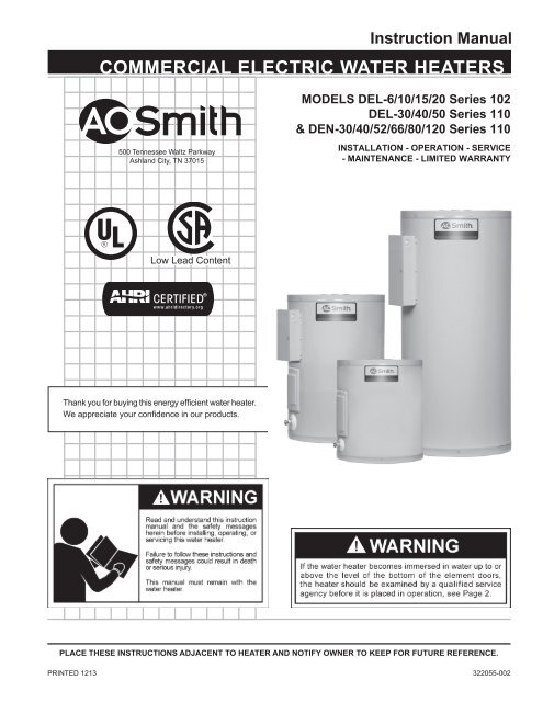
Instruction Manual<br />
COMMERCIAL ELECTRIC WATER HEATERS<br />
MODELS DEL-6/10/15/20 Series 102<br />
DEL-30/40/50 Series 110<br />
& DEN-30/40/52/66/80/120 Series 110<br />
500 Tennessee Waltz Parkway<br />
Ashland City, TN 37015<br />
INSTALLATION - OPERATION - SERVICE<br />
- MAINTENANCE - LIMITED WARRANTY<br />
Thank you for buying this energy efficient water heater.<br />
We appreciate your confidence in our products.<br />
place these instructions adjacent to heater and notify owner to keep for future reference.<br />
PRINTED 1213 <strong>322055</strong>-002<br />
1
SAFE INSTALLATION, USE, AND SERVICE<br />
The proper installation, use and servicing of this water heater is extremely important to your safety and the safety of others.<br />
Many safety-related messages and instructions have been provided in this manual and on your own water heater to warn you and<br />
others of a potential injury hazard. Read and obey all safety messages and instructions throughout this manual. It is very important<br />
that the meaning of each safety message is understood by you and others who install, use, or service this water heater.<br />
This is the safety alert symbol. It is used to alert you<br />
to potential personal injury hazards. Obey all safety<br />
messages that follow this symbol to avoid possible<br />
injury or death.<br />
DANGER<br />
WARNING<br />
CAUTION<br />
CAUTION<br />
DANGER indicates an imminently hazardous<br />
situation which, if not avoided, will result in<br />
death or injury.<br />
WARNING indicates a potentially hazardous<br />
situation which, if not avoided, could result<br />
in death or injury.<br />
CAUTION indicates a potentially hazardous<br />
situation which, if not avoided, could result<br />
in minor or moderate injury.<br />
CAUTION used without the safety alert<br />
symbol indicates a potentially hazardous<br />
situation which, if not avoided, could result<br />
in property damage.<br />
All safety messages will generally tell you about the type of hazard, what can happen if you do not follow the safety message, and<br />
how to avoid the risk of injury.<br />
The California Safe Drinking <strong>Water</strong> and Toxic Enforcement Act requires the Governor of California to publish a list of substances<br />
known to the State of California to cause cancer, birth defects, or other reproductive harm, and requires businesses to warn of<br />
potential exposure to such substances.<br />
This product contains a chemical known to the State of California to cause cancer, birth defects, or other reproductive harm. This<br />
appliance can cause low level exposure to some of the substances listed in the Act.<br />
IMPORTANT DEFINITIONS<br />
• Qualified Installer or Service Agency:<br />
Installation and service of this water heater requires ability equivalent to that of a Qualified Agency (as defined by ANSI below) in the<br />
field involved. Installation skills such as plumbing, electrical supply are required in addition to electrical testing skills when performing<br />
service.<br />
• ANSI Z223.1 2006 Sec. 3.3.83:<br />
“Qualified Agency” - “Any individual, firm, corporation or company that either in person or through a representative is engaged in and is<br />
responsible for (a) the installation, testing or replacement of gas piping or (b) the connection, installation, testing, repair or servicing of<br />
appliances and equipment; that is experienced in such work; that is familiar with all precautions required; and that has complied with all<br />
the requirements of the authority having jurisdiction.”<br />
2
GENERAL SAFETY INFORMATION<br />
Precautions<br />
Hydrogen Gas (Flammable)<br />
DO NOT USE THIS WATER HEATER IF ANY PART HAS BEEN<br />
UNDER WATER. Immediately call a qualified service technician<br />
to inspect the water heater and to replace any part of the control<br />
system which has been under water.<br />
If the unit is exposed to the following, do not operate heater until<br />
all corrective steps have been made by a qualified service agency.<br />
1. External fire.<br />
2. Damage.<br />
3. Firing without water.<br />
GROUNDING INSTRUCTIONS<br />
This water heater must be grounded in accordance with the<br />
National Electrical Code and/or local codes. These must be<br />
followed in all cases. Failure to ground this water heater properly<br />
may also cause erratic control system operation on ELECTRONIC<br />
CONTROL models.<br />
This water heater must be connected to a grounded metal, permanent<br />
wiring system; or an equipment grounding conductor must be run with<br />
the circuit conductors and connected to the equipment grounding<br />
terminal or lead on the water heater.<br />
Hydrogen gas can be produced in a hot water system served by this<br />
heater that has not been used for a long period of time (generally two<br />
weeks or more). Hydrogen gas is extremely flammable. To reduce the<br />
risk of injury under these conditions, it is recommended that the hot water<br />
faucet be opened for several minutes at the kitchen sink before using any<br />
electrical appliance connected to the hot water system. If hydrogen is present<br />
there will probably be an unusual sound such as air escaping through the<br />
pipe as the water begins to flow. THERE SHOULD BE NO SMOKING<br />
OR OPEN FLAME NEAR THE FAUCET AT THE TIME IT IS OPEN.<br />
When servicing this unit, verify the power to the unit is turned off prior to opening the control cabinet door.<br />
3
TABLE OF CONTENTS<br />
SAFE INSTALLATION, USE, AND SERVICE....................................... 2<br />
GENERAL SAFETY INFORMATION.................................................... 3<br />
Precautions................................................................................... 3<br />
Hydrogen Gas (Flammable).......................................................... 3<br />
Introduction................................................................................... 4<br />
Preparing for the Installation......................................................... 4<br />
dimensions and capacities data............................................... 5<br />
APPROVALS......................................................................................... 6<br />
model and rating........................................................................... 6<br />
FEATURES AND COMPONENTS........................................................ 7<br />
Electronic Control Models............................................................. 7<br />
LOCATING THE NEW WATER HEATER.............................................. 8<br />
Facts to Consider About the Location........................................... 8<br />
Clearances.................................................................................... 8<br />
iNSTALLATION..................................................................................... 9<br />
Required Ability............................................................................. 9<br />
General......................................................................................... 9<br />
Contaminated <strong>Water</strong>..................................................................... 9<br />
Circulating Pump........................................................................... 9<br />
Insulation Blankets........................................................................ 9<br />
Temperature-Pressure Relief Valve.............................................. 9<br />
Closed <strong>Water</strong> Systems................................................................ 10<br />
Thermal Expansion..................................................................... 10<br />
electrical.......................................................................................11<br />
General........................................................................................11<br />
Branch Circuit..............................................................................11<br />
Calculating Amperage/Overcurrent Protection.............................11<br />
WIRING DIAGRAMS........................................................................... 12<br />
OPERATION....................................................................................... 13<br />
General....................................................................................... 13<br />
Filling the <strong>Water</strong> Heater.............................................................. 13<br />
Initial Start Up............................................................................. 13<br />
Draining the <strong>Water</strong> Heater.......................................................... 13<br />
TEMPERATURE REGULATION......................................................... 14<br />
Temperature Adjustment............................................................. 14<br />
MAINTENANCE.................................................................................. 15<br />
General....................................................................................... 15<br />
Anode Rod Inspection................................................................. 15<br />
TROUBLESHOOTING CHECKLIST................................................... 16<br />
Checklist..................................................................................... 16<br />
Leakage Checkpoints................................................................. 17<br />
WARRANTY........................................................................................ 18<br />
nOTES................................................................................................ 19<br />
Repair Parts List......................................................................... 20<br />
Introduction<br />
Thank You for purchasing this water heater. Properly installed<br />
and maintained, it should give you years of trouble free service.<br />
Abbreviations Found In This Instruction Manual:<br />
• ANSI - American National Standards Institute<br />
• AHRI - Air-Conditioning, Heating and Refrigeration Institute<br />
• NEC - National Electrical Code<br />
• NFPA - National Fire Protection Association<br />
• UL - Underwriters Laboratory<br />
Preparing for the Installation<br />
1. Read the “General Safety Information” section of this manual<br />
first and then the entire manual carefully. If you don’t follow<br />
the safety rules, the water heater may not operate safely. It<br />
could cause DEATH, SERIOUS BODILY INJURY AND/OR<br />
PROPERTY DAMAGE.<br />
This manual contains instructions for the installation, operation,<br />
and maintenance of the electric water heater. It also contains<br />
warnings throughout the manual that you must read and be<br />
aware of. All warnings and all instructions are essential to the<br />
proper operation of the water heater and your safety. READ<br />
THE ENTIRE MANUAL BEFORE ATTEMPTING TO INSTALL<br />
OR OPERATE THE WATER HEATER.<br />
4<br />
Be sure to turn off power when working on or near the<br />
electrical system of the heater. Never touch electrical<br />
components with wet hands or when standing in water.<br />
When replacing fuses always use the correct size for the<br />
circuit. see page 12.<br />
The model and rating plates on page 6 interprets certain<br />
markings into useful information. Both of these references should<br />
be used to identify the heater, its components and optional<br />
equipment.<br />
2. The installation must conform with these instructions and the<br />
local code authority having jurisdiction and the requirements<br />
of the power company. In the absence of local codes, the<br />
installation must comply with the latest editions of the National<br />
Electrical Code, NFPA 70 or the Canadian Electrical Code CSA<br />
C22.1. The National Electrical Code may be ordered from:<br />
National Fire Protection Association, 1 Batterymarch Park,<br />
Quincy, MA 02269. The Canadian Electrical Code is available<br />
from the Canadian Standards Association, 8501 East Pleasant<br />
Valley Road, Cleveland, OH 44131.<br />
3. If after reading this manual you have any questions or do not<br />
understand any portion of the instructions, call the toll free<br />
number listed on the back cover of this manual for technical<br />
assistance.<br />
A sample rating plate is shown on page 6 of this manual. In<br />
order to expedite your request, please have full model and serial<br />
number available for the technician.<br />
4. Carefully plan your intended placement of the water heater.<br />
Examine the location to ensure the water heater complies with<br />
the “Locating the New <strong>Water</strong> Heater” section in this manual.<br />
Installation and service of this water heater requires ability<br />
equivalent to that of a licensed tradesman or qualified agency<br />
(page 2) in the field involved. Plumbing and electrical work<br />
are required.
dimensions and capacities data<br />
Figure 1<br />
Models<br />
Dimensions<br />
No. of<br />
Elements<br />
Table 1 - Rough-in dimensions<br />
Tank Capacity A B C D<br />
Approx.<br />
Shipping Weight<br />
US Gals. Litres inches mm inches mm inches mm inches mm Lbs. Kg.<br />
DEL-6 1 6 23 15 1/2 394 14 1/4 362 11 279 - - 35 15.9<br />
DEL-10 1 10 38 18 1/4 464 18 457 12 1/2 318 - - 54 24.5<br />
DEL-15 1 15 57 26 660 18 457 20 1/2 521 - - 58 26.3<br />
DEL-20 1 20 76 22 1/4 565 21 3/4 552 15 3/8 391 - - 73 33.1<br />
DEL-30 2 30 114 30 7/8 784 21 3/4 552 24 1/8 613 8 203 100 45.4<br />
DEL-40 2 40 151 32 1/4 819 24 610 25 9/16 649 8 203 125 56.7<br />
DEL-50 2 50 189 32 1/4 819 26 1/2 673 25 1/8 638 8 203 166 75.3<br />
DEN-30 2 30 114 34 1/2 876 20 1/2 521 - - 8 203 98 44.5<br />
DEN-40 2 40 151 45 1/8 1146 20 1/2 521 - - 8 203 113 51.3<br />
DEN-52 2 50 189 54 7/8 1394 20 1/2 521 - - 8 203 131 59.4<br />
DEN-66 2 66 250 60 3/4 1543 21 3/4 552 - - 8 203 176 79.8<br />
DEN-80 2 80 303 59 3/8 1508 24 610 - - 8 203 211 95.7<br />
DEN-120 2 119 450 62 7/16 1586 29 3/8 746 - - 8 203 326 147.9<br />
Element<br />
Wattage<br />
(Upper/Lower)<br />
INPUT<br />
KW<br />
Table 2 - Recovery capacities<br />
u.S. Gallons/Hr and Litres/Hr at TEMPERATURE RISE INDICATED<br />
F° 36F° 40F° 54F° 60F° 72F° 80F° 90F° 100F° 108F° 120F° 126F°<br />
C° 20C° 22.2C° 30C° 33.3C° 40C° 44.4C° 50C° 55.5C° 60C° 66.6C° 70C°<br />
NON-SIMULATANEOUS<br />
/1500 GPH 17 15 11 10 8 8 7 6 6 5 5<br />
1.5 LPH 64 58 43 38 32 29 26 23 21 19 18<br />
/2<strong>000</strong> GPH 23 20 15 14 11 10 9 8 8 7 6<br />
2.0 LPH 85 77 57 51 43 38 34 31 28 26 24<br />
/2500 GPH 28 25 19 17 14 13 11 10 9 8 8<br />
2.5 LPH 107 96 71 64 53 48 43 38 36 32 30<br />
3<strong>000</strong>/3<strong>000</strong> GPH 34 30 23 20 17 15 14 12 11 10 10<br />
3.0 LPH 128 115 85 77 64 58 51 46 43 38 37<br />
4<strong>000</strong>/4<strong>000</strong> GPH 45 41 30 27 23 20 18 16 15 14 13<br />
4.0 LPH 170 153 114 102 85 77 68 61 57 51 49<br />
4500/4500 GPH 51 46 34 30 25 23 20 18 17 15 14<br />
4.5 LPH 192 173 128 115 96 86 77 69 64 58 55<br />
5<strong>000</strong>/5<strong>000</strong> GPH 56 51 38 34 28 25 23 20 19 17 16<br />
5.0 LPH 213 192 142 128 107 96 85 77 71 64 61<br />
6<strong>000</strong>/6<strong>000</strong> GPH 68 61 45 41 34 30 27 24 23 20 19<br />
6.0 LPH 256 230 170 153 128 115 102 92 85 77 73<br />
SIMULATANEOUS OPERATION<br />
3<strong>000</strong>/3<strong>000</strong> GPH 68 61 45 41 34 30 27 24 23 20 19<br />
6 LPH 256 230 170 153 128 115 102 92 85 77 73<br />
4<strong>000</strong>/4<strong>000</strong> GPH 90 81 60 54 45 41 36 32 30 27 26<br />
8 LPH 341 307 227 205 170 153 136 123 114 102 97<br />
4500/4500 GPH 101 91 68 61 51 46 41 36 34 30 29<br />
9 LPH 384 345 256 230 192 173 153 138 128 115 110<br />
5<strong>000</strong>/5<strong>000</strong> GPH 113 101 75 68 56 51 45 41 38 34 32<br />
10 LPH 426 384 284 256 213 192 170 153 142 128 122<br />
6<strong>000</strong>/6<strong>000</strong> GPH 135 122 90 81 68 61 54 49 45 41 39<br />
12 LPH 511 460 341 307 256 230 205 184 170 153 146<br />
Recovery capacities at 100° F rise equal: for non-simultaneous element operation = 4.1 gal. x KW of one element; for simultaneous element operation = 4.1 gal. x 2/3 KW of<br />
both elements. For other rises multiply element KW as previously explained by 410 and divide by temperature rise. Full load current for single phase = total watts : voltage.<br />
5
APPROVALS<br />
All models are listed by<br />
Underwriters Laboratories Inc.<br />
model and rating<br />
DEL-30/40/50 & DEN-30/40/52/66/80/120<br />
DEL-6/10/15/20<br />
6
Electronic Control Models<br />
FEATURES AND COMPONENTS<br />
This page shows typical water heater installations by model designations.<br />
DEN/DEL DUAL ELEMENT HEATER<br />
DEN/DEL SINGLE ELEMENT HEATER<br />
INSTALL SUITABLE DRAIN PANS UNDER WATER HEATERS<br />
TO PREVENT DAMAGE DUE TO LEAKAGE. REFER TO WATER<br />
HEATER LOCATION ON page 8.<br />
INSTALL THERMAL<br />
EXPANSION TANK<br />
IF CHECK VALVE OR<br />
PRESSURE REDUCING<br />
VALVE IS USED IN<br />
SUPPLY LINE.<br />
INSTALL VACUUM RELIEF<br />
IN COLD WATER INLET<br />
LINE AS REQUIRED BY<br />
LOCAL CODES.<br />
† OVER CURRENT PROTECTION MUST BE SUPPLIED IN WATER HEATER CIRCUIT.<br />
CONSULT LOCAL CODE OR NEC-1984 FOR PROPER INSTALLATION.<br />
* INSTALL IN ACCORDANCE WITH ALL LOCAL CODES.<br />
Figure 2<br />
7
LOCATING THE NEW WATER HEATER<br />
Facts to Consider About the Location<br />
The water heater should be located as close as possible to/or<br />
centralized to the water piping system. The water heater should<br />
be located in an area not subject to freezing temperatures.<br />
The water heater should be located in an area where leakage<br />
of the tank or connections will not result in damage to the area<br />
adjacent to the heater or to lower floors of the structure.<br />
When such locations cannot be avoided, a suitable drain pan<br />
should be installed under the heater.<br />
Such pans should be at least two inches deep, have a minimum<br />
length and width of at least two inches greater than the diameter<br />
of the heater and should be piped to an adequate drain.<br />
Drain pans suitable for these water heaters are available from<br />
your distributor or A.O. <strong>Smith</strong> <strong>Water</strong> Heater Parts Fulfillment,<br />
125 Southeast Parkway, Franklin, TN 37068.<br />
<strong>Water</strong> heater life depends upon water quality, water pressure<br />
and the environment in which the water heater is installed. <strong>Water</strong><br />
heaters are sometimes installed in locations where leakage may<br />
result in property damage, even with the use of a drain pan piped<br />
to a drain. However, unanticipated damage can be reduced or<br />
prevented by a leak detector or water shut-off device used in<br />
conjunction with a piped drain pan. These devices are available<br />
from some plumbing supply wholesalers and retailers, and detect<br />
and react to leakage in various ways:<br />
• Sensors mounted in the drain pan that trigger an alarm or turn<br />
off the incoming water to the water heater when leakage is<br />
detected.<br />
• Sensors mounted in the drain pan that turn off the water<br />
supply to the entire home when water is detected in the<br />
drain pan.<br />
• <strong>Water</strong> supply shut-off devices that activate based on the water<br />
pressure differential between the cold water and how water<br />
pipes connected to the water heater.<br />
• Devices that will turn off the gas supply to a gas water heater<br />
while at the same time shutting off its water supply.<br />
Clearances<br />
A minimum clearance of 4” must be allowed for access to<br />
replaceable parts such as thermostats, drain valve and relief<br />
valve.<br />
Adequate clearance for servicing this water heater should be<br />
considered before installation, such as changing the anodes, etc.<br />
FLOOD WARNING<br />
IF THE HEATER BECOMES IMMERSED IN WATER UP TO<br />
OR ABOVE THE LEVEL OF THE BOTTOM OF THE ELEMENT<br />
DOORS, THE HEATER SHOULD BE EXAMINED BY A<br />
COMPETENT SERVICE PERSON BEFORE IT IS PLACED IN<br />
OPERATION.<br />
8
iNSTALLATION<br />
Required Ability<br />
Installation and service of this water heater requires ability equivalent<br />
to that of a qualified installer or service agency (page 2) in the<br />
field involved. Plumbing and electrical work is required.<br />
General<br />
The installation must conform with these instructions and the local<br />
code authority having jurisdiction and the requirements of the power<br />
company. In the absence of local codes, the installation must comply<br />
with the latest editions of the National Electrical Code, NFPA 70 or<br />
the Canadian Electrical Code CSA C22.1. The National Electrical<br />
Code may be ordered from: National Fire Protection Association,<br />
1 Batterymarch Park, Quincy, MA 02269. The Canadian Electrical<br />
Code is available from the Canadian Standards Association, 8501<br />
East Pleasant Valley Road, Cleveland, OH 44131.<br />
Do NOT test electrical system before heater is filled with water, follow<br />
the START UP procedure in the OPERATION section of this manual.<br />
The principal components of the heater are identified in the<br />
Features and Components illustrations on page 7.<br />
Contaminated <strong>Water</strong><br />
This water heater shall not be connected to any heating system(s)<br />
or component(s) used with a non-potable water heating appliance.<br />
Toxic chemicals, such as those used for boiler treatment shall not<br />
be introduced into this system.<br />
Circulating Pump<br />
Field installed circulating pumps should be of all bronze<br />
construction.<br />
Insulation Blankets<br />
Insulation blankets are available to the general public for<br />
external use on electric water heaters but are not necessary with<br />
this product. The purpose of an insulation blanket is to reduce<br />
the standby heat loss encountered with storage tank heaters.<br />
Your water heater meets or exceeds the EPACT and ASHRAE/<br />
IES 90.1 standards with respect to insulation and standby loss<br />
requirements, making an insulation blanket unnecessary.<br />
Should you choose to apply an insulation blanket to this heater,<br />
you should follow these instructions below. Failure to follow<br />
these instructions can result in fire, serious personal injury,<br />
or death.<br />
• Do not cover the temperature and pressure relief (T & P) valve<br />
with an insulation blanket.<br />
• Do not cover the instruction manual. Keep it on the side of the<br />
water heater or nearby for future reference.<br />
• Do obtain new warning and instruction labels for placement on<br />
the blanket directly over the existing labels.<br />
Temperature-Pressure Relief Valve<br />
MIXING VALVE USAGE:<br />
<strong>Water</strong> heaters are intended to produce hot water. <strong>Water</strong> heated to<br />
a temperature which will satisfy space heating, clothes washing,<br />
dish washing, cleaning and other sanitizing needs can scald and<br />
permanently injure you upon contact. Some people are more likely<br />
to be permanently injured by hot water than others. These include<br />
the elderly, children, the infirm, or physically/developmentally<br />
disabled. If anyone using hot water in your home fits into one of<br />
these groups or if there is a local code or state law requiring a<br />
maximum water temperature at the hot water tap, then you must<br />
take special precautions. In addition to using the lowest possible<br />
temperature setting that satisfies your hot water needs, a means<br />
such as a MIXING VALVE, should be used at the hot water taps<br />
used by these people or at the water heater.<br />
MIXING VALVES for reducing point of use temperature are available<br />
and are to be set at a maximum of 125 degree F. Consult a qualified<br />
installer or service agency. Follow all manufacturer’s Instructions<br />
for installation of these valves. Before changing the factory setting<br />
on the thermostat, read the “Temperature Regulation” section in<br />
this manual.<br />
This water heater is provided with a properly rated/sized and<br />
certified combination temperature - pressure relief valve by the<br />
manufacturer. The valve is certified by a nationally recognized<br />
testing laboratory that maintains periodic inspection of production<br />
of listed equipment of materials as meeting the requirements for<br />
Relief Valves for Hot <strong>Water</strong> Supply Systems, ANSI Z21.22 • CSA<br />
4.4, and the code requirements of ASME.<br />
If replaced, the new valve must meet the requirements of local<br />
codes, but not less than a combination temperature and pressure<br />
relief valve rated/sized and certified as indicated in the above<br />
9
paragraph. The new valve must be marked with a maximum set<br />
pressure not to exceed the marked hydrostatic working pressure<br />
of the water heater (150 psi = 1,035 kPa) and a discharge capacity<br />
not less than the water heater Btu/hr or KW input rate as shown on<br />
the water heater’s model rating plate.<br />
For safe operation of the water heater, the temperature and pressure<br />
relief valve must not be removed from its designated opening nor<br />
plugged. The temperature-pressure relief valve must be installed<br />
directly into the fitting of the water heater designed for the relief valve.<br />
Install discharge piping so that any discharge will exit only within 6<br />
inches (15.2 cm) above, or at any distance below the structural floor.<br />
Be certain that no contact is made with any live electrical part. The<br />
discharge opening must not be blocked or reduced in size under<br />
any circumstances. Excessive length, over 30 feet (9.14 m), or<br />
use of more than four elbows can cause restriction and reduce the<br />
discharge capacity of the valve.<br />
No valve or other obstruction is to be placed between the relief valve<br />
and the tank. Do not connect discharge piping directly to the drain<br />
unless a 6” (15.2 cm) air gap is provided. To prevent bodily injury,<br />
hazard to life, or property damage, the relief valve must be allowed<br />
to discharge water in adequate quantities should circumstances<br />
demand. If the discharge pipe is not connected to a drain or other<br />
suitable means, the water flow may cause property damage.<br />
The Discharge Pipe:<br />
• Shall not be smaller in size than the outlet pipe size of the valve, or<br />
have any reducing couplings or other restrictions.<br />
• Shall not be plugged or blocked.<br />
• Shall be of material listed for hot water distribution.<br />
• Shall be installed so as to allow complete drainage of both the<br />
temperature-pressure relief valve and the discharge pipe.<br />
• Must terminate a maximum of six inches above a floor drain or<br />
external to the building. In cold climates, it is recommended that the<br />
discharge pipe be terminated at an adequate drain inside the building.<br />
• Shall not have any valve or other obstruction between the relief<br />
valve and the drain.<br />
The temperature-pressure relief valve must be manually operated<br />
at least once a year. Caution should be taken to ensure that (1) no<br />
one is in front of or around the outlet of the temperature-pressure<br />
relief valve discharge line, and (2) the water manually discharged<br />
can cause bodily injury or property damage because the water<br />
may be extremely hot. If after manually operating the valve, it fails<br />
to completely reset and continues to release water, immediately<br />
close the cold water inlet to the water heater, follow the draining<br />
instructions in this manual, and replace the temperature-pressure<br />
relief valve with a properly rated/sized new one.<br />
If you do not understand these instructions or have any questions<br />
regarding the temperature-pressure relief valve call the toll free<br />
number listed on the back cover of this manual for technical assistance.<br />
Closed <strong>Water</strong> Systems<br />
<strong>Water</strong> supply systems may, because of code requirements or such<br />
conditions as high line pressure, among others, have installed<br />
devices such as pressure reducing valves, check valves, and back<br />
flow preventers. Devices such as these cause the water system to<br />
be a closed system.<br />
Thermal Expansion<br />
As water is heated, it expands (thermal expansion). In a closed system<br />
the volume of water will grow when it is heated. As the volume of<br />
water grows there will be a corresponding increase in water pressure<br />
due to thermal expansion. Thermal expansion can cause premature<br />
tank failure (leakage). This type of failure is not covered under the<br />
limited warranty. Thermal expansion can also cause intermittent<br />
temperature-pressure relief valve operation: water discharged from<br />
the valve due to excessive pressure build up. This condition is not<br />
covered under the limited warranty. The temperature-pressure relief<br />
valve is not intended for the constant relief of thermal expansion.<br />
A properly sized thermal expansion tank should be installed on all<br />
closed systems to control the harmful effects of thermal expansion.<br />
Contact a local plumbing service agency to have a thermal expansion<br />
tank installed.<br />
10
General<br />
The installation must conform with these instructions and the local<br />
code authority having jurisdiction and the requirements of the power<br />
company. In the absence of local codes, the installation must comply<br />
with the current editions of the National Electrical Code, NFPA 70 or<br />
the Canadian Electrical Code CSA C22.1.<br />
An electrical ground is required to reduce risk of electrical shock<br />
or possible electrocution. The water heater should be connected<br />
to a separate grounded branch circuit with over-current protection<br />
and disconnect switch. The water heater should be grounded in<br />
accordance with national and local codes.<br />
Voltage applied to the heater should not vary more than +5% to -10%<br />
of the model and rating plate marking for satisfactory operation.<br />
DO NOT ENERGIZE THE BRANCH CIRCUIT FOR ANY REASON<br />
BEFORE THE HEATER TANK IS FILLED WITH WATER. DOING<br />
SO WILL CAUSE THE HEATING ELEMENTS TO BURN OUT AND<br />
VOID WARRANTY.<br />
The factory wiring is attached to a terminal block within the external<br />
junction box unit. The branch circuit is connected to the terminal<br />
block within this junction box. The water heater should be connected<br />
to a separate, grounded, branch circuit with overcurrent protection<br />
and disconnect switch. The water heater should be grounded in<br />
accordance with national and local codes.<br />
Branch Circuit<br />
The branch circuit wire size should be established through reference<br />
to the current edition of NFPA-70, the National Electrical Code<br />
or other locally approved source in conjunction with the heater<br />
amperage rating. For convenience, portions of the wire size tables<br />
from the Code are reproduced here. The branch circuit should be<br />
sized at 125 percent of the heater rating and further increase wire<br />
size as necessary to compensate for voltage drop in long runs.<br />
Calculating Amperage/Overcurrent Protection<br />
The heaters come from the factory in two configurations:<br />
1. Two wire C-2 circuit for single element heater equipped with a<br />
high limit control, single phase power input.<br />
2. Four wire A-8 circuit for dual element heater equipped with two<br />
high limit controls, single phase or three phase power input.<br />
The heater with dual elements is factory wired for connection to<br />
a three wire, three-phase delta branch circuit, non-simultaneous<br />
operation. In addition a ground conductor is required.<br />
Element connection is for non-simultaneous operation. This means<br />
only one element at a time operates. The wiring diagram, on page<br />
12, shows the heater may be field converted to simultaneous<br />
element operation by moving the red wire on “J” terminal to L1. It is<br />
then possible for both elements to operate at once as determined<br />
by the thermostats. Regardless of element connection the heater<br />
operates in an “unbalanced” fashion.<br />
The heater may be field converted to single-phase operation by moving<br />
the wire on L3 of the terminal block to L2. L3 is not used, see page 12.<br />
The heater, now in single-phase non-simultaneous operation, may<br />
be field-converted to single phase simultaneous operation by moving<br />
the red wire on terminal “J” to L1, see page 12.<br />
electrical<br />
11<br />
This is an example of calculating heater amperage for both types<br />
of element operation. From this, the branch circuit conductor and<br />
overcurrent protection sizing can be established.<br />
The example is of a three-phase 240 volt unit with two, 6 kw<br />
elements. The notations are for units field converted to single-phase.<br />
Check the heater model and rating plate for actual specifications<br />
and substitute those values in the following.<br />
Non-simultaneous:<br />
(as factory wired)<br />
3<strong>000</strong> : 240 = 12.5 amps*<br />
*NOTE: as a single-phase nonsimultaneous<br />
unit.<br />
Table 3<br />
Simultaneous:<br />
(Field conversion)<br />
3<strong>000</strong> : 240 = 12.5 amps*<br />
12.5 x 1.73 = 21.6 amps<br />
*NOTE: as a single-phase<br />
simultaneous unit the total is:<br />
12.5 x 2 = 25 amps<br />
The rating of the overcurrent protection should be computed on the<br />
basis of 125 percent of the total connected load amperage. Where the<br />
standard ratings and settings do not correspond with this computation,<br />
the next higher standard rating or setting should be selected.<br />
Portion of Table 310-16 (NFPA-70) follows:<br />
Allowable Ampacities of Insulated Copper Conductors. Not more<br />
than three conductors in Raceway or Cable or Direct Burial (Based<br />
on Ambient Temperature of 30° C, 86° F).<br />
These ampacities relate only to conductors described in Table<br />
310-13 in Code.<br />
For ambient temperatures over 30° C (86° F), see Correction<br />
Factors, Note 13 in Code.<br />
For ambient temperatures over 30° C (86° F), see Correction<br />
Factors, Note 13 in Code.<br />
Size<br />
AMG<br />
MCM<br />
18<br />
16<br />
14<br />
12<br />
10<br />
8<br />
6<br />
4<br />
3<br />
Table 4<br />
Temperature Rating of Conductor<br />
See Table 310-13 in Code<br />
60°C<br />
75°C<br />
(140°F)<br />
(167°F)<br />
Types:<br />
RUW, (14-2), T, TW, UF<br />
- - -<br />
- - -<br />
15<br />
20<br />
30<br />
40<br />
55<br />
70<br />
80<br />
Types:<br />
RH, RHW, RUH, (14-2),<br />
THW, THWN, XHHW, USE<br />
- - -<br />
- - -<br />
15<br />
20<br />
30<br />
45<br />
65<br />
85<br />
100<br />
Portion of Table 310-18 follows:<br />
Allowable Ampacities of Insulated Aluminum and Copper -Clad<br />
Aluminum Conductors.<br />
Not more than three conductors in Raceway or Cable or Direct Burial<br />
(Based on Ambient Temperature of 30° C, 86° F. These ampacities<br />
relate only to conductors described in Table 310-13 in Code.<br />
For ambient temperatures over 30° C (86° F), see Correction Factors,<br />
Note 13 in Code.<br />
Size<br />
AMG<br />
MCM<br />
12<br />
10<br />
8<br />
6<br />
4<br />
3<br />
2<br />
1<br />
Table 5<br />
Temperature Rating of Conductor<br />
See Table 310-13 in Code<br />
60°C<br />
75°C<br />
(140°F)<br />
(167°F)<br />
Types:<br />
RUW, (12-2), T, TW, UF<br />
15<br />
25<br />
30<br />
40<br />
55<br />
65<br />
75<br />
85<br />
Types:<br />
RH, RHW, RUH, (12-2),<br />
THW, THWN, XHHW, USE<br />
15<br />
25<br />
40<br />
50<br />
65<br />
75<br />
90<br />
100
WIRING DIAGRAMS<br />
A-8 CIRCUIT FOR DUAL ELEMENT HEATER<br />
C-2 CIRCUIT<br />
FOR SINGLE<br />
ELEMENT HEATERS<br />
EQUIPPED WITH HIGH<br />
LIMIT CONTROL<br />
FACTORY WIRED<br />
---------- FIELD WIRING<br />
† WHITE FOR 120V & 277V<br />
Figure 3<br />
12
General<br />
Refer to the Features and Components section of this manual (page<br />
7) for the location of components mentioned in the instructions<br />
that follow.<br />
NEVER turn on power to the water heater without being certain the<br />
water heater is filled with water and a temperature and pressure<br />
relief valve is installed in the relief valve opening.<br />
DO NOT TEST ELECTRICAL SYSTEM BEFORE HEATER IS<br />
FILLED WITH WATER. FOLLOW FILLING AND START-UP<br />
INSTRUCTIONS IN OPERATION SECTION.<br />
Filling the <strong>Water</strong> Heater<br />
1. Turn off the electrical disconnect switch.<br />
2. Close the water heater drain valve.<br />
3. Open a nearby hot water faucet to permit the air in the system<br />
to escape.<br />
4. Fully open the cold water inlet pipe valve allowing the heater and<br />
piping to be filled.<br />
5. Close the hot water faucet as water starts to flow. The<br />
heater is now ready for STARTUP and TEMPERATURE<br />
REGULATION.<br />
OPERATION<br />
Initial Start Up<br />
The following checks should be made by the installer when the heater<br />
is placed into operation for the first time.<br />
1. Turn off the electrical disconnect switch.<br />
2. Open the front panel or top access cover, check all water and<br />
electrical connections for tightness. Also check connections on top<br />
and or sides of heater. Repair water leaks and tighten electrical<br />
connections as necessary.<br />
3. Depress the red manual reset button on each Thermostat/ECO<br />
combination control. (See Figure 5, Figure 6, Figure 7, or Figure 8)<br />
4. Turn on the electrical disconnect switch.<br />
5. Observe the operation of the electrical components during the first<br />
heating cycle. Use care as the electrical circuits are energized.<br />
6. Close the front panel or top access cover.<br />
Temperature control and contactor operation should be checked by<br />
allowing heater to come up to temperature and shut off automatically.<br />
Use care as the electrical circuits are energized.<br />
Draining the <strong>Water</strong> Heater<br />
The water heater must be drained if it is to be shut down and exposed<br />
to freezing temperatures. Maintenance and service procedures may<br />
also require draining the heater.<br />
1. Turn off the electrical disconnect switch.<br />
2. Open a hot water valve until the water is cool, then close the<br />
supply water inlet valve to heater.<br />
3. Attach hose to outlet opening of drain valve and direct end to drain.<br />
4. Open a nearby hot water faucet and the heater drain valve.<br />
5. If the heater is being drained for an extended shutdown, it is<br />
suggested the drain valve be left open during this period. The<br />
hose may be removed.<br />
Follow FILLING instructions when restoring hot water service.<br />
INSTALLATION<br />
13
TEMPERATURE REGULATION<br />
approximately the 140°F (60°C) setting. The over temperature device<br />
(ECO high limit) attached to each thermostat has a manual reset.<br />
40A 120-277 VAC<br />
25A.480-600 VAC<br />
125VA.PT.DTY.<br />
120-480 VAC<br />
MODEL<br />
WH10C<br />
MED<br />
APCOM<br />
INC<br />
THE WATER HEATER IS EQUIPPED WITH AN ADJUSTABLE<br />
THERMOSTAT TO CONTROL WATER TEMPERATURE. HOT<br />
WATER AT TEMPERATURES DESIRED FOR AUTOMATIC<br />
DISHWASHER AND LAUNDRY USE CAN CAUSE SCALDS<br />
RESULTING IN SERIOUS PERSONAL INJURY AND/OR DEATH.<br />
THE TEMPERATURE AT WHICH INJURY OCCURS VARIES WITH<br />
THE PERSON’S AGE AND TIME OF EXPOSURE. THE SLOWER<br />
RESPONSE TIME OF CHILDREN , AGED OR DISABLED PERSONS<br />
INCREASES THE HAZARD TO THEM. NEVER ALLOW SMALL<br />
CHILDREN TO USE A HOT WATER TAP, OR TO DRAW THEIR OWN<br />
BATH WATER. NEVER LEAVE A CHILD OR DISABLED PERSON<br />
UNATTENDED IN A BATHTUB OR SHOWER.<br />
It is recommended that lower water temperatures be used to avoid<br />
the risk of scalding. It is further recommended, in all cases, that the<br />
water temperature thermostats (See Figure 4) be set for the lowest<br />
temperature which satisfies your hot water needs. This will also<br />
provide the most energy efficient operation of the water heater.<br />
Figure 4 shows the approximate time-to-burn relationship for<br />
normal adult skin. The thermostats on your water heater have a<br />
linear relationship between degrees of angular rotation and the<br />
corresponding change in temperature. Thus rotating the temperature<br />
adjustment indicator 30 angular degrees will result in a 10 degree<br />
Fahrenheit change in water temperature.<br />
30A 120-250 VAC<br />
22A 277 VAC<br />
12.5A 480-600VAC<br />
125 VA.PT.DTY. 120-480 VAC<br />
Figure 5 Figure 6<br />
THERMODISC THERMOSTATS<br />
A-8 circuit thermostats are adjustable from approximately 120°F<br />
(49°C) (lowest setting) to 180°F (82°C) (highest setting) (See Figure<br />
7). The C-2 circuit thermostat is adjustable from approximately 110°F<br />
(43°C) to 170°F (77°C) (See Figure 8). These thermostats are set<br />
from the factory at approximately the 140°F (60°C) setting. The over<br />
temperature device (ECO high limit) attached to each thermostat<br />
has a manual reset.<br />
L1<br />
L2<br />
T1<br />
T2<br />
RESET<br />
RESET<br />
89T<br />
THERM O DISC<br />
L3<br />
L4<br />
T4<br />
L1<br />
L2<br />
T1<br />
T2<br />
RESET<br />
RESET<br />
THERM-O-DISC<br />
L3<br />
L4<br />
T4<br />
<strong>Water</strong> Temperature<br />
°F (°C)<br />
Time for 1st Degree Burn<br />
(Less Severe Burns)<br />
Time for Permanent Burns<br />
2nd & 3rd Degree<br />
(Most Severe Burns)<br />
110 (43) (normal shower temp.)<br />
116 (47) (pain threshold)<br />
116 (47) 35 minutes 45 minutes<br />
122 (50) 1 minute 5 minutes<br />
131 (55) 5 seconds 25 seconds<br />
140 (60) 2 seconds 5 seconds<br />
149 (65) 1 second 2 seconds<br />
154 (68) instantaneous 1 second<br />
(U.S. Government Memorandum, C.P.S.C., Peter L. Armstrong, Sept. 15, 1978)<br />
Figure 4<br />
Temperature Adjustment<br />
The water heater is supplied with thermostats that may come from<br />
different manufactures and have different temperature indications<br />
as described below.<br />
APCOM THERMOSTATS<br />
A-8 Circuit thermostats have three designated set points; LO, MED<br />
and HI. (See Figure 5).The approximate equivalent temperatures for<br />
these three settings are: LO = 140°F (60°C), MED = 160°F (71°C) and<br />
HI = 180°F (82°C). These thermostats are set from the factory at the<br />
LO 140°F (60°C) setting. The over temperature device (ECO high<br />
limit) attached to each thermostat has a manual reset. The C-2 circuit<br />
thermostat is adjustable from approximately 130°F (54°C) to 170°F<br />
(77°C) (See Figure 6). These thermostats are set from the factory at<br />
14<br />
180°F 120°F<br />
140°F<br />
170°F<br />
140°F<br />
110°F<br />
Figure 7 Figure 8<br />
NOTE: It is not necessary to adjust the upper thermostat for a dual<br />
element unit. However, if it is adjusted above the factory set point<br />
140°F (60°C) it is recommended that it not be set higher than the<br />
lower thermostat setting.<br />
To change the temperature setting:<br />
1. DANGER: Turn off the heater electrical supply. Do not attempt<br />
to adjust thermostat with power on.<br />
2. Open the junction box door (for upper thermostat of dual<br />
element water heater only) and/or remove the (lower) thermostat<br />
access panel. Do not remove the plastic personnel protectors<br />
covering the thermostats. The thermostat is factory pre-set at<br />
140°F (60°C).<br />
3. Using a flat tip screwdriver, rotate the adjusting knob to the<br />
desired temperature setting.<br />
4. Replace the covers and access panels, and turn on heater<br />
electrical supply.
MAINTENANCE<br />
General<br />
Anode Rod Inspection<br />
Periodically the drain valve should be opened and the water<br />
allowed to run until it flows clean. This will help to prevent<br />
sediment buildup in the tank bottom.<br />
Periodically check the temperature and pressure relief valve<br />
to ensure that it is in operating condition. Lift the lever at the<br />
top of the valve several times until the valve seats properly<br />
and operates freely.<br />
<strong>Water</strong> heater maintenance includes periodic tank flushing and<br />
cleaning, and removal of lime scale from the heating element.<br />
The heater tank is equipped with an anode rod to aid in<br />
corrosion control.<br />
The anode rod is used to protect the tank from corrosion. Most hot<br />
water tanks are equipped with an anode rod. The submerged rod<br />
sacrifices itself to protect the tank. Instead of corroding tank, water<br />
ions attack and eat away the anode rod. This does not affect water’s<br />
taste or color. The rod must be maintained to keep tank in operating<br />
condition.<br />
Anode deterioration depends on water conductivity, not necessarily<br />
water condition. A corroded or pitted anode rod indicates high water<br />
conductivity and should be checked and/or replaced more often than<br />
an anode rod that appears to be intact. Replacement of a depleted<br />
anode rod can extend the life of your water heater. Inspection should<br />
be conducted by a qualified technician, and at a minimum should be<br />
checked annually after the warranty period.<br />
Artificially softened water is exceedingly corrosive because the<br />
process substitutes sodium ions for magnesium and calcium ions.<br />
The use of a water softener may decrease the life of the water<br />
heater tank.<br />
The anode rod should be inspected after a maximum of three years<br />
and annually thereafter until the condition of the anode rod dictates<br />
its replacement.<br />
NOTE: Artificially softened water requires the anode rod to be<br />
inspected annually.<br />
15
TROUBLESHOOTING CHECKLIST<br />
Checklist<br />
Before calling for service, check the following points to see if the<br />
cause of trouble can be identified and corrected.<br />
Reviewing this checklist may eliminate the need of a service call<br />
and quickly restore hot water service. See Figure 2 on page 7 in this<br />
manual to identify and locate water heater components.<br />
Not enough or no hot water<br />
1. Be certain the electrical disconnect switch serving the water heater<br />
is in the ON position.<br />
2. Check the fuses.<br />
• The electrical disconnect switch usually contains fuses.<br />
3. If the water was excessively hot, and is now cold, the high limit<br />
switch may have activated.<br />
• See the Temperature Regulation section of this manual for<br />
more information on how to reset the ECO high limit controls.<br />
4. The capacity of the heater may have been exceeded by a large<br />
demand for hot water.<br />
• Large demands require a recovery period to restore water<br />
temperature.<br />
5. Cooler incoming water temperature will lengthen the time required<br />
to heat water to the desired temperature.<br />
6. Look for hot water leakage.<br />
7. Sediment or pipe scale may be affecting water heater operation.<br />
ABNORMAL SOUNDS<br />
1. Sediment or lime scale accumulations on the elements causes<br />
sizzling and hissing noises when the heater is operating.<br />
• The sounds are normal, however, the tank bottom and<br />
elements should be cleaned. See the Maintenance section<br />
of this manual.<br />
<strong>Water</strong> leakage is suspected<br />
Refer to Leakage Checkpoint on the following page 17.<br />
1. Check to see if the heater drain valve is tightly closed.<br />
2. If the outlet of the relief valve is leaking it may represent:<br />
• Excessive water temperature.<br />
• Faulty relief valve.<br />
• Excessive water pressure.<br />
3. Excessive water pressure is the most common cause of relief valve<br />
leakage. It is often caused by a “closed system”. See “Closed<br />
<strong>Water</strong> Systems” and “Thermal Expansion” in the Installation<br />
section of this manual for more information.<br />
4. Examine the area around the element for gasket leakage.<br />
• Tighten the elements or, if necessary, follow the WATER<br />
AND LIME SCALE REMOVAL procedure to replace the<br />
gaskets.<br />
IF YOU CANNOT IDENTIFY OR CORRECT THE SOURCE OF<br />
MALFUNCTION<br />
1. Turn the power supply to the water heater off.<br />
2. Close the supply water inlet valve to the heater.<br />
3. Contact a Qualified Service Agency in your area. Call the toll free<br />
phone number on the back cover of this Instruction Manual for<br />
assistance in locating a service agency in your area.<br />
REPLACEMENT PARTS<br />
Call the toll free phone number on the back cover of this Instruction<br />
Manual for assistance in locating replacement parts.. When ordering<br />
parts, specify complete model no., serial no., (see rating plate),<br />
quantity and name of part desired. Standard hardware items should<br />
be purchased locally.<br />
16
Leakage Checkpoints<br />
Instructions: Use this illustration as a guide when checking for sources of water leakage. You or your dealer may be able to correct what<br />
appears to be a problem. NOTE: Cover and Insulation shown removed to reveal tank top.<br />
Where possible remove or lift top cover to<br />
examine threads of fittings installed into tank<br />
for evidence of leakage. Correct fitting leaks<br />
as necessary.<br />
<strong>Water</strong> leaks at the elements may be due<br />
to:<br />
1. Defective element which leaks at<br />
terminals or thru flange. Replace<br />
element*.<br />
2. Loose element/gasket leak:<br />
(a) Screw-in type: tighten with 1-1/2”<br />
socket wrench. If leak continues,<br />
remove element*, discard gasket<br />
and clean thread areas.Apply<br />
nonhardening Permatex Number 2<br />
to thread areas, install new gasket<br />
and screw element into fitting until<br />
it seats. Tighten 1/2 to 3/4 turn with<br />
wrench.<br />
(b) Flange type: tighten screw with<br />
wrench. If leak continues remove<br />
element* and discard gasket. Clean<br />
gasket seating areas and re-install<br />
element with new gasket. A new<br />
element may be required where<br />
threads have become rusted or<br />
damaged, preventing tightening.<br />
All water which appears at the water<br />
heater bottom or on the surrounding floor<br />
may be caused by condensation, loose<br />
connections or relief valve operation<br />
and leakage. Do not replace the water<br />
heater until full inspection of all potential<br />
leak points is made and corrective steps<br />
taken to stop the leak. Leakage from other<br />
appliances, water lines or ground (see<br />
page 16) should also be suspected until<br />
proven otherwise.<br />
Relief Valve<br />
Anode Rod (Some Models)<br />
Figure 9<br />
To Open Drain<br />
Condensation and dripping may appear<br />
on pipes when cold water temperature is<br />
low. Pipe fitting may be leaking.<br />
Relief valve operation and leakage<br />
may be due to water expansion during<br />
heating cycle or foreign material on seat<br />
of valve. If the valve is not piped to an<br />
open drain the released water could be<br />
mistaken for a leaking heater. To check<br />
where threaded material between jacket<br />
opening and swab spud area. Remove<br />
valve* if indicated and repair with pipe<br />
joint compound.<br />
To Open Drain<br />
<strong>Water</strong> on the side of the tank may<br />
be condensation due to the panel or<br />
insulation not being in place.<br />
Drain valve leakage could be from the<br />
valve itself.* To check for leakage where<br />
threaded portion enters tank, insert Q-tip<br />
or similar absorbent material between<br />
jacket opening and valve to swab spud<br />
area. Remove valve* if leak is indicated<br />
and repair with pipe joint compound.<br />
*Contact your dealer as it is necessary to<br />
shut off electricity and drain tank to perform<br />
procedure.<br />
17
WARRANTY<br />
A. O. <strong>Smith</strong> Corporation, the warrantor, extends the following LIMITED WARRANTY to the owner of this water heater:<br />
1. THE TANK<br />
If the glass-lined tank in this water heater shall prove upon examination by the warrantor to have leaked due to natural corrosion from potable<br />
water therein, during the first THREE years after initial installation, the warrantor will supply a complete new A. O. <strong>Smith</strong> water heater of equivalent<br />
size and current model. Some government agencies are requiring energy efficient standards for water heaters. In the event regulations prohibit<br />
sale of a model of equivalent size and construction, A. O. <strong>Smith</strong> will provide a model which complies with the regulations of your area, in which<br />
case the consumer will be charged the difference in price between the like replacement and the energy efficient model required. The warranty on<br />
the replacement water heater will be limited to the unexpired term of the original warranty.<br />
2. ALL OTHER PARTS<br />
If within ONE year after initial installation of this water heater, any part or portion shall prove upon examination by the warrantor to be defective in<br />
material or workmanship, the warrantor will repair or replace such part or portion at its option.<br />
3. CONDITIONS and EXCEPTIONS<br />
This warranty shall apply only when the water heater is installed in accordance with local plumbing and building codes, ordinances and regulations,<br />
the printed instructions provided with it and good industry practices. In addition, a temperature and pressure relief valve, certified by A.G.A.and<br />
approved by the American Society of Mechanical Engineers, must have been installed.<br />
a. This warranty shall apply only when the heater is used:<br />
(1) at temperatures not exceeding the maximum setting of its thermostat;<br />
(2) at water pressure not exceeding the working pressure shown on the water heater;<br />
(3) when filled with potable water, free to circulate at all times;<br />
(4) in a noncorrosive and non-contaminated atmosphere;<br />
(5) in the United States, its territories or possessions, and Canada.<br />
(6) used with factory approved anode(s) installed;<br />
(7) in its original installation location;<br />
(8) sized in accordance with proper sizing techniques for commercial water heaters;<br />
(9) bearing a rating plate which has not been altered, defaced or removed except as required by the warrantor;<br />
(10) not used in a closed system without a properly sized and installed thermal expansion tank;<br />
(11) fired at the proper voltage and wattage;<br />
(12) maintained in accordance with the instructions printed in the manual included with the heater.<br />
b. Any accident to the water heater, any misuse, abuse (including freezing) or alteration of it, any operation of it in a modified<br />
form, or any attempt to repair tank leaks will void this warranty.<br />
4. SERVICE and REPAIR EXPENSE<br />
Under this limited warranty the warrantor will provide only a replacement water heater or part thereof. The owner is responsible for all other costs.<br />
Such costs may include but are not limited to:<br />
a. Labor charges for service, removal, repair, or reinstallation of the water heater or any component part;<br />
b. Shipping, delivery, handling, and administrative charges for forwarding the new heater or replacement part from the nearest<br />
distributor and returning the claimed defective heater or part to such distributor;<br />
c. All cost necessary or incidental for any materials and/or permits required for installation of the replacement heater or part.<br />
5. LIMITATIONS ON IMPLIED WARRANTIES<br />
Implied warranties, including any warranty of merchantability imposed on the sale of this heater under state law are limited to one (1) year duration for the<br />
heater or any of its parts. Some states do not allow limitations on how long an implied warranty lasts, so the above limitation may not apply to you.<br />
6. CLAIM PROCEDURE<br />
Any claim under this warranty should be initiated with the dealer who sold the heater, or with any other dealer handling the warrantor’s products.<br />
If this is not practicable, the owner should contact:<br />
U.S. Customers<br />
Canadian Customers<br />
A. O. <strong>Smith</strong> GSW <strong>Water</strong> Heating<br />
500 Tennessee Waltz Parkway 599 Hill Street West<br />
Ashland City, TN 37015<br />
Fergus, ON N1M 2X1<br />
Telephone: 1.800.527.1953 Telephone: 1.888.479.8324<br />
a. The warrantor will only honor replacement with identical or similar water heater or parts thereof which are manufactured or<br />
distributed by the warrantor.<br />
b. Dealer replacements are made subject to in-warranty validation by warrantor.<br />
7. DISCLAIMERS<br />
NO OTHER EXPRESS WARRANTY HAS BEEN OR WILL BE MADE IN BEHALF OF THE WARRANTOR WITH RESPECT TO THE<br />
MERCHANTABILITY OF THE HEATER OR THE INSTALLATION, OPERATION, REPAIR, OR REPLACEMENT OF THE HEATER. THE<br />
WARRANTOR SHALL NOT BE RESPONSIBLE FOR WATER DAMAGE, LOSS OF USE OF THE UNIT, INCONVENIENCE, LOSS OR DAMAGE<br />
TO PERSONAL PROPERTY, OR OTHER CONSEQUENTIAL DAMAGE. THE WARRANTOR SHALL NOT BE LIABLE BY VIRTUE OF THIS<br />
WARRANTY OR OTHERWISE FOR DAMAGE TO ANY PERSONS OR PROPERTY, WHETHER DIRECT OR INDIRECT, AND<br />
WHETHER ARISING IN CONTRACT OR IN TORT.<br />
a. Some states do not allow the exclusion or limitation of the incidental or consequential damage, so the above limitation or<br />
exclusion may not apply to you.<br />
b. This warranty gives you specific legal rights, and you may also have other rights which vary from state to state.<br />
Fill in the following for your own reference. Keep it. Registration is not a condition of warranty. The model and serial number are found on the heater’s rating plate.<br />
Model No.________________________________________ Serial No.________________________________ Date Installed ________________<br />
Dealer’s Name_________________________________________________________________________________________________________<br />
Dealer’s Address _______________________________________________________________________Phone No. _______________________<br />
City and State __________________________________________________________________________Zip ____________________________<br />
18
nOTES<br />
19
Repair Parts List<br />
Now that you have purchased this water heater, should a need ever<br />
exist for repair parts or service, simply contact the company it was<br />
purchased from or direct from the manufacturer listed on the rating<br />
plate on the water heater.<br />
Selling prices will be furnished on request or parts will be shipped<br />
at prevailing prices and you will be billed accordingly.<br />
The model number of your <strong>Water</strong> Heater will be found on the rating<br />
plated located above the lower access panel.<br />
Be sure to provide all pertinent facts when you call or visit.<br />
WHEN ORDERING REPAIR PARTS, ALWAYS GIVE THE<br />
FOLLOWING INFORMATION:<br />
• MODEL NUMBER<br />
• VOLTAGE AND ELEMENT WATTAGE<br />
• SERIAL NUMBER<br />
• PART DESCRIPTION<br />
Del 6, 10, 15, 20 Series 102 (refer to repair parts table).<br />
DRAIN VALVE<br />
(not supplied with heater)<br />
Part No. 26273-5<br />
Figure 10<br />
20
Item Description del-6 del-10 del-15 DEL-20<br />
series 102 Series 102 Series 102 Series 102<br />
1A........Anode, Alum... ................................... 9003942005......... 9003942005........ 9003942005....... 9003944005<br />
1B........Anode, Mag. (SMR P72 and S19)...... 9001909005......... 9001909005........ 9001909005....... 9003721005<br />
2.........Collar, Pipe..........................................9004610115......... 9004610115.........9004610115....... 9004610115<br />
3.........Cover, Front........................................ 90039<strong>000</strong>05......... 90039<strong>000</strong>05........ 90039<strong>000</strong>05....... 90039<strong>000</strong>05<br />
4.........ELEMENT, HEATING................................... .SEE ELEMENT CHART ON page 23.........................<br />
5.........Gasket, Element................................. 9<strong>000</strong>308005......... 9<strong>000</strong>308005........ 9<strong>000</strong>308005....... 9<strong>000</strong>308005<br />
6.........Opening Insulation...............................043307-<strong>000</strong>...........043307-<strong>000</strong>..........043307-<strong>000</strong>........ 043307-<strong>000</strong><br />
7.........*Instruction Manual................................<strong>322055</strong>-0...............<strong>322055</strong>-0..............<strong>322055</strong>-0............ <strong>322055</strong>-0<br />
10........Personnel Protector............................ 9003914015......... 9003914015........ 9003914015....... 9003914015<br />
11........Pipe Nipple............................................. 194130................194130-3..............194130-3............ 194130-3<br />
12........Plate, Knockout.......................................43293-1.................43293-1................43293-1.............. 43293-1<br />
PLUG<br />
15/16......Thermostat with High Limit Switch...... 9006586015......... 9006586015........ 9006586015....... 9006586015<br />
17........Bracket, Thermostat........................... 9003898015......... 9003898015........ 9003898015....... 9003898015<br />
18........Valve, Relief........................................ 9003484005......... 9003741005........ 9003741005....... 9003741005<br />
*Not Illustrated.<br />
Standard Hardware Items May Be Purchased Locally. Underlined Parts Are Recommended For Emergency Replacement.<br />
DEN 30, 40, 52, 66, 80 & 120, Series 110<br />
(Refer to Repair Parts Table on page 22)<br />
DEL 30, 40 & 50, Series 110<br />
(Refer to Repair Parts Table on page 22)<br />
Figure 11 Figure 12<br />
21
Item Description del-30 DEL-40 DEL-50 DEN-30 DEN-40 DEN-52 DEN-66 DEN-80 DEN-120<br />
series 110 Series 110 Series 110 Series 110 Series 110 Series 110 Series 110 Series 110 Series 110<br />
1A.....Anode, Alum. ............................. 9003944005....9003944005.... 9003944005....9003944005....9003944005.... 9003944005... 9<strong>000</strong>029005.... 9003892005....9003892005<br />
1B.....Anode, Mag.(SMR P72)............ 9003721005....9003721005.... 9003721005....9003721005....9003721005.... 9003721005... 9003721005.... 9001829005....9001829005<br />
2......T&P Relief Valve........................ 9003741005....9003741005.... 9003741005....9<strong>000</strong>071005....9<strong>000</strong>071005.... 9<strong>000</strong>071005... 9<strong>000</strong>071005.... 9<strong>000</strong>071005....9<strong>000</strong>071005<br />
3......Gasket, Element........................ 9<strong>000</strong>308045....9<strong>000</strong>308045.... 9<strong>000</strong>308045....9<strong>000</strong>308045....9<strong>000</strong>308045.... 9<strong>000</strong>308045... 9<strong>000</strong>308045.... 9<strong>000</strong>308045....9<strong>000</strong>308045<br />
4......ELEMENT, each............................................................................................... (SEE ELEMENT & WATTAGE CHART page 23 ) .....................................................................<br />
5......Upper Thermostat w/Hi Limit..... 9002856015....9002856015.... 9002856015....9002856015....9002856015.... 9002856015... 9002856015.... 9002856015....9002856015<br />
6......Lower Thermostat w/Hi Limit..... 9002857015....9002857015.... 9002857015....9002857015....9002857015.... 9002857015... 9002857015.... 9002857015....9002857015<br />
7......Thermostat Bracket, each......... 9003898215....9003898215.... 9003898215....9003898215....9003898215.... 9003898215... 9003898215.... 9003898215....9003898215<br />
8......Personal Protector..................... 9003914015....9003914015.... 9003914015....9003914015....9003914015.... 9003914015... 9003914015.... 9003914015....9003914015<br />
9......Lower Access Panel.................. 90039<strong>000</strong>05....90039<strong>000</strong>05.... 90039<strong>000</strong>05....90039<strong>000</strong>05....90039<strong>000</strong>05.... 90039<strong>000</strong>05... 90039<strong>000</strong>05.... 90039<strong>000</strong>05....90039<strong>000</strong>05<br />
10.....Dip Tube..................................... 9003902005....9003902005.... 9003902005....9003902005....9003903005.... 9003904005... 9003905005.... 9003905005....9005709205<br />
11.....Power Terminal.......................... 9005719215....9005719215.... 9005719215....9005719215....9005719215.... 9005719215... 9005719215.... 9005719215....9005719215<br />
12.....Drain Valve................................. 9003906015....9003906015.... 9003906015....9003906015....9003906015.... 9003906015... 9003906015.... 9003906015....9003906015<br />
15*....Junction Box Assembly..................195171............195171............ 195171.............195171............ 195171.............195171............195171.............195171............195171<br />
16*....Manual...........................................<strong>322055</strong>-0......... <strong>322055</strong>-0.........<strong>322055</strong>-0......... <strong>322055</strong>-0..........<strong>322055</strong>-0.........<strong>322055</strong>-0.........<strong>322055</strong>-0..........<strong>322055</strong>-0......... <strong>322055</strong>-0<br />
*Not Illustrated.<br />
Standard Hardware Items May Be Purchased Locally.<br />
Underlined Parts Are Recommended For Emergency Replacement.<br />
22
Figure 13<br />
Table 6 - COPPER SHEATH ELEMENT AND WATTAGE CHART<br />
K.W.<br />
ELEMENT<br />
WATTAGE<br />
120V 208V 240V 277V 480V<br />
PART NO. PART NO. PART NO. PART NO. PART NO.<br />
1.0 1<strong>000</strong>W - - - 9002863115 9<strong>000</strong>1431005 - - - - - -<br />
1.5 1500W 9002963005 9<strong>000</strong>145005 9002864005 9001225115 - - -<br />
2.0 2<strong>000</strong>W 9003947005 9002858005 9<strong>000</strong>145005 9004709115 - - -<br />
2.5 2500W 9002859005 9004712105 900286<strong>000</strong>5 900289<strong>000</strong>5 9002861005<br />
3.0 3<strong>000</strong>W 9002862005 9002868005 9003959005 9003958005 9003961005<br />
3.5 3500W - - - 900395<strong>000</strong>5 9004712105 - - - - - -<br />
MAX 3.5KW INPUT FOR 6 GALLON UNITS, ELEMENTS BELOW DOTTED LINE CANNOT BE USED ON 6 GALLON UNITS<br />
4.0 4<strong>000</strong>W - - - 9002867005 9002868005 9001229005 9002869005<br />
4.5 4500W - - - 9003952005 9003950100 900396<strong>000</strong>5 9001225005<br />
5.0 5<strong>000</strong>W - - - 9001224005 9003957005 9001231005 9001236005<br />
5.5 5500W - - - 9002871005 9002867005 - - - 9002872005<br />
6.0 6<strong>000</strong>W - - - 9003953005 9003952005 9002874005 9002875005<br />
Table 7 - Incoloy Sheath Element and Wattage Chart (for SMR P72)<br />
K.W.<br />
ELEMENT<br />
WATTAGE<br />
120 V 208 V 240 V 277 V 480 V<br />
PART NO. PART NO. PART NO. PART NO. PART NO.<br />
1.5 1500 W 9004279005 9004283005 900429<strong>000</strong>5 9004736105 Not Available<br />
2.0 2<strong>000</strong> W 900428<strong>000</strong>5 9004284005 9004283005 900429<strong>000</strong>5 9004298005<br />
2.5 2500 W 9004281005 9004285005 9004291005 9004295005 9004299005<br />
INCOLOY ELEMENTS BELOW THIS LINE CANNOT BE USED ON 6 GALLON UNITS BECAUSE OF ELEMENT LENGTH<br />
3.0 3<strong>000</strong> W 9004282005 9004751115 9<strong>000</strong>664005 9004296005 90043<strong>000</strong>05<br />
3.5 3500 W Not Available 900321<strong>000</strong>5 9004292005 Not Available Not Available<br />
4.0 4<strong>000</strong> W Not Available 9004294005 9004751115 9<strong>000</strong>664005 Not Available<br />
4.5 4500 W Not Available 9004287005 900321<strong>000</strong>5 9004297005 9004301005<br />
5.0 5<strong>000</strong> W Not Available 9004753105 9004293005 Not Available Not Available<br />
5.5 5500 W Not Available 9004288005 9004294005 Not Available Not Available<br />
6.0 6<strong>000</strong> W Not Available 9004289005 9004287005 Not Available Not Available<br />
23
www.hotwater.com<br />
500 Tennessee Waltz Parkway, Ashland City, TN 37015<br />
Tech Support: 800-527-1953<br />
Parts: 800-433-2545<br />
Copyright © 2012 A. O. <strong>Smith</strong> <strong>Water</strong> Heater Company, All rights reserved.<br />
24


