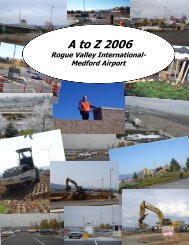
rogue valley international medford airport - Jackson County Oregon
rogue valley international medford airport - Jackson County Oregon
rogue valley international medford airport - Jackson County Oregon

Create successful ePaper yourself
Turn your PDF publications into a flip-book with our unique Google optimized e-Paper software.
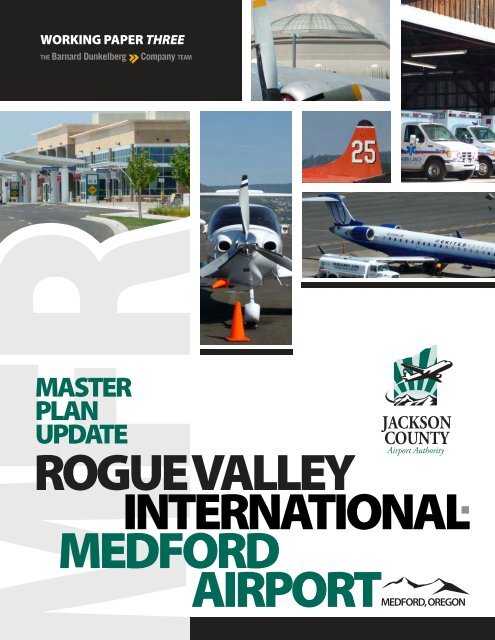
WORKING PAPER THREE<br />
THE Barnard Dunkelberg<br />
Company TEAM<br />
MASTER<br />
PLAN<br />
UPDATE<br />
JACKSON<br />
COUNTY<br />
Airport Authority<br />
ROGUE VALLEY<br />
INTERNATIONAL<br />
MEDFORD<br />
AIRPORTMEDFORD, OREGON
WORKING PAPER THREE<br />
July 2011<br />
THE Barnard Dunkelberg<br />
Company TEAM<br />
Barnard Dunkelberg<br />
Company<br />
TULSA<br />
Cherry Street Building<br />
1616 East 15th Street<br />
Tulsa, Oklahoma 74120-6027<br />
Phone Number. 918 585 8844<br />
FAX Number. 918 585 8857<br />
DENVER<br />
1743 Wazee Street, Suite 400<br />
Denver, Colorado 80202<br />
Phone Number. 303 825 8844<br />
FAX Number. 303 825 8855<br />
Email Address. mark@bd-c.com<br />
Precision Approach Engineering<br />
Corvallis, <strong>Oregon</strong><br />
Leibowitz & Horton AMC<br />
Seattle, Washington<br />
MASTER<br />
PLAN<br />
UPDATE<br />
JACKSON<br />
COUNTY<br />
Airport Authority<br />
ROGUE VALLEY<br />
INTERNATIONAL<br />
MEDFORD<br />
AIRPORTMEDFORD, OREGON
Contents<br />
Contents<br />
Illustrations<br />
iii<br />
iv<br />
CHAPTER D. Development Concepts and Alternatives Analysis<br />
Goals and Objectives for Development D.2<br />
Runway 14/32 Instrument Approach Improvement Analysis D.3<br />
Airside Development Concepts and Sketches D.5<br />
Landside Development Concepts and Sketches D.17<br />
Alternatives Environmental Screening D.29<br />
Conceptual Development Plan D.31<br />
iii
Illustrations<br />
Figure D1 RUNWAY 14 AND 32 INSTRUMENT APPORACH AND MISSED<br />
D.4<br />
APPROACH AREA OF TERPS SCREENING<br />
Figure D2 AIRSIDE ALTERNATIVE ONE, INIITAL RUNWAY 14L32R (ARC B-II) D.7<br />
Figure D3 AIRSIDE ALTERNATIVE TWO, ULITIMATE RUNWAY 14L32R (ARC C-<br />
D.10<br />
II)<br />
Figure D4 AIRSIDE ALTERNATIVE THREE, ULTIMATE RUNWAY 14L/32R (ARC<br />
D.13<br />
C-II) UTILIZES ALL OF INITIAL RUNWAY DEVELOPMENT<br />
PAVEMENT<br />
Figure D5 AIRSIDE ALTERNATIVE FOUR, ULTIMATE RUNWAY 13/31 (ARC C-<br />
D.16<br />
II) NO LAND ACQUISITION REQUIRED<br />
Figure D6 TAXIWAY “C” DEVELOPMENT PROPOSAL D.19<br />
Figure D7 TAXILANE DEVELOPMENT OPTION D.20<br />
Figure D8 TAXIWAY “C” DEVELOPMENT AREA LAYOUT CONCEPT ONE D.22<br />
Figure D9 TAXIWAY “C” DEVELOPMENT AREA LAYOUT CONCEPT TWO D.24<br />
Figure D10 TAXIWAY “C” DEVELOPMENT AREA LAYOUT CONCEPT THREE D.26<br />
Figure D11 EASTSIDE LANDSIDE ACCESS CONCEPT D.28<br />
Figure D12 EXISTING ENVIRONMENTAL CONSIDERATIONS SUMMARY D.30<br />
iv
D. Development Concepts and Alternatives Analysis<br />
INTRODUCTION. The purpose of this chapter is to present development alternatives and<br />
development recommendations for Rogue Valley International-Medford Airport in<br />
terms of concepts and reasoning. This chapter provides a description of the various<br />
factors and influences, which will form the basis for the Airport’s long-term<br />
development program.<br />
In concert with the role of the Airport and community input received in the planning<br />
process, several basic assumptions have been established that are intended to direct<br />
the development of the Airport in the future.<br />
Assumption One. The Airport will be developed and operated in a manner that is consistent with<br />
local ordinances and codes, federal and state statutes, federal grant assurances, and federal agency<br />
regulations (e.g., Federal Aviation Administration, Transportation Security Administration, and<br />
Environmental Protection Agency, among others).<br />
Assumption Two. This assumption recognizes the role of the Airport. The Airport will continue to<br />
serve as a facility that accommodates commercial passenger service activity, along with general<br />
aviation activity, air cargo/freight activity, and a small amount of military activity.<br />
Assumption Three. This assumption relates to the size and type of aircraft that utilize the Airport and<br />
the resulting setback and safety criteria used as the basis for the layout of associated <strong>airport</strong> facilities.<br />
Runway 14/32. The “Design Aircraft” for this runway was identified in the previous chapter as the<br />
McDonnell Douglas MD-83. The MD-83 aircraft has an approach speed of approximately 144<br />
knots and a wingspan of approximately 108 feet making the ARC for the aircraft D-III. However,<br />
the runway also accommodates a number of large fire bomber/tanker aircraft with wingspans in the<br />
Group IV category and the previous Airport Master Plan recommended protection for the potential<br />
to upgrade the ARC for Runway 14/32 to ARC D-IV. Alternatives considered in this chapter will<br />
continue to the protect for a future ARC of D-IV for Runway 14/32.<br />
Future Runway 14L/32R. As mentioned in previous chapters, this runway has historically been<br />
shown on the Airport Layout Plan for Rogue Valley International-Medford Airport and has been<br />
D. 1
intended to be used primarily by smaller general aviation aircraft. However, in order to maximize<br />
the potential safety and operational benefits of this runway, consideration should be given to<br />
accommodating the majority of the general aviation fleet up to and including the business jet fleet.<br />
The recommended future “Design Aircraft” for this runway is a small to medium sized business jet<br />
such as the Dassault Falcon 900. It is also recommended that an ultimate ARC of C-II be considered<br />
for this future runway in order to better accommodate the commercial aircraft fleet in the event that<br />
the primary runway at the Airport needs to be closed for maintenance, rehabilitation, or an<br />
emergency. An ARC of C-II would also allow the runway to accommodate more regular use by the<br />
business jet aircraft fleet. This forward thinking concept would allow for ultimate flexibility and<br />
operational readiness that could become a potential significant benefit to airlines and corporate flight<br />
departments alike. If constructed, it is likely that this future runway would be a phased project with<br />
the initial phase being built to ARC B-II standards (capable of regularly accommodating the majority<br />
of the general aviation fleet up to and including many of the smaller business jets).<br />
Assumption Four. The fourth assumption relates to the need for the Airport to accommodate aircraft<br />
operations with great reliability and safety. This indicates that the Airport’s runway system should<br />
be developed with instrument approach guidance capabilities, to accommodate the forecast<br />
operations as safely as possible under most weather conditions.<br />
Assumption Five. Because the amount of landside development area at any <strong>airport</strong> is at a premium,<br />
the fifth assumption is that the plan for future <strong>airport</strong> development should strive to make most<br />
efficient use of the available area for aviation-related activities, including general aviation facilities<br />
and passenger terminal facilities. Aviation use areas should be developed to be compatible with<br />
surrounding land uses.<br />
Assumption Six. The sixth assumption focuses on the relationship of the Airport to off-<strong>airport</strong> land<br />
uses and the compatible and complementary development of each. To the maximum extent<br />
possible, future facilities will be designed to enhance the compatibility of the operation of the<br />
Airport with the environs.<br />
Goals and Objectives for Development<br />
Accompanying these assumptions are several goals and objectives, which have been established for<br />
purposes of directing the plan and establishing continuity in the future development of the Airport.<br />
These goals and objectives take into account several categorical considerations relating to the needs<br />
of the Airport, both in the short-term and the long-term, including safety, noise, capital<br />
improvements, land use compatibility, financial and economic conditions, public interest and<br />
D. 2
investment, and community recognition and awareness. While all are project oriented, some<br />
obviously represent more tangible activities than others; however, all are deemed important and<br />
appropriate to the future of the Airport.<br />
The following goals and objectives are intended to guide the preparation of this Airport Master Plan<br />
Update and direct the future expansion of the Rogue Valley International-Medford Airport:<br />
• Provide effective direction for the future development of the Airport through the<br />
preparation of a rational, reasonable, and implementable plan.<br />
• Prepare a plan that allows the Airport to fulfill the mission of facilitating and enhancing<br />
regional aviation services by right-sizing to meet future demand.<br />
• Accommodate the forecast aviation activity levels in a safe and efficient manner by<br />
providing the necessary <strong>airport</strong> facilities and services.<br />
• Ensure that the future development of the Airport will accommodate a variety of general<br />
aviation activities, ranging from small general aviation users to corporate aviation, and<br />
commercial aviation operators.<br />
• Plan and develop the Airport to be capable of accommodating the future needs and<br />
requirements of the City of Medford, <strong>Jackson</strong> <strong>County</strong> and the larger surrounding service<br />
area and support regional economic development activity.<br />
• Plan for potential property acquisition for approach protection and land use compatibility<br />
purposes.<br />
• Encourage and protect the public and private investment in land and facilities.<br />
Runway 14/32 Instrument Approach Improvement Analysis<br />
An instrument approach assessment has been prepared for the Rogue Valley International-Medford<br />
Airport utilizing the approach clearance criteria in FAA Order 8260.3B, Terminal Instrument<br />
Procedures (TERPS) and FAA Part 77, Objects Affecting Navigable Airspace focusing on the final and<br />
missed approach courses to each runway end at MFR. Preliminary indications suggest that it may be<br />
possible to enhance instrument approach capabilities to one or more runway ends. However,<br />
revaluation of the initial assessment will be conducted as part of the final screening for the<br />
Conceptual Development Plan. See the following figure D.1 that depicts the area of analysis.<br />
D. 3
THE Barnard Dunkelberg Company TEAM<br />
Runway 14<br />
Approach<br />
Runway 32<br />
Approach<br />
0<br />
2,500<br />
5,000 7,500<br />
Approximate Scale 1” = 5,000’<br />
10,000<br />
Figure D1<br />
Runway 14/32 Precision Instrument<br />
Approach (PIR) + Missed Approach<br />
MASTER PLAN<br />
UPDATE<br />
ROGUE VALLEY<br />
INTERNATIONAL MEDFORD<br />
AIRPORT<br />
D.4
Airside Development Concepts and Sketches<br />
Because all other <strong>airport</strong> functions relate to and revolve around the basic runway/taxiway layout,<br />
airside development alternatives must first be carefully examined and evaluated. It is essential that<br />
the initial development recommendations for the Airport be commensurate with the anticipated<br />
needs and requirements of <strong>airport</strong> users; however, the long-term improvement of the facility must<br />
also be considered and planned for to ensure the capability to accommodate potential activity levels.<br />
The main objective of the planning recommendations presented herein is to identify future<br />
development that will result in a runway/taxiway system capable of accommodating the forecast<br />
aviation activity. The recommendations are described in the following sections. In the following<br />
working paper, an environmental screening of the alternatives will be included ultimately leading to<br />
a recommended CONCEPTUAL DEVELOPMENT PLAN for Rogue Valley International-Medford<br />
Airport.<br />
Following a review of these airside development alternatives, the purpose of which is to fulfill major<br />
facility requirements (basic runway configuration), recommendations for landside development are<br />
presented. For purposes of this study, landside facilities consist of aircraft parking aprons, hangar<br />
development areas, terminal area development, and <strong>airport</strong> access.<br />
Airside Alternative One<br />
As explained in the previous chapter, the runway length requirements of those aircraft using the<br />
Airport on a regular basis are met with the existing length of Runway 14/32 and it is recommended<br />
that this runway be maintained as is. The primary purpose of Alternative One is to increase the<br />
safety and utility of the Airport by segregating traffic and providing separate runway facilities for<br />
both large and small aircraft.<br />
Alternative One includes the provision of a parallel runway east of Runway 14/32 designed to<br />
Airport Reference Code (ARC) B-II standards with dimensions of 4,600 feet by 75 feet. The runway<br />
facility includes visual approaches to both ends and is located at a standard 700-foot separation from<br />
Runway 14/32.<br />
New Runway 14L/32R ARC B-II<br />
• The Airport’s primary Runway (Runway 14/32) would remain in its existing<br />
configuration.<br />
• The instrument approach visibility minimums to Runway 32 would be upgraded to a ¾<br />
mile visibility minimum and the Runway Protection Zone (RPZ) would increase in size.<br />
D. 5
• The acquisition of approximately 24 acres of easement is recommended for the existing<br />
RPZ to the approach end of Runway 14.<br />
• A parallel runway (Runway 14L/32R) would be constructed at a 700-foot separation from<br />
the primary runway designed to Airport Reference Code B-II standards with visual<br />
approaches to both runway ends.<br />
• The acquisition of approximately 5 acres of land would be required for the RPZ to the<br />
approach end of Runway 14L.<br />
Positive Qualities of Alternative One<br />
• Provides an improved instrument approach from the south (to the Runway 32 end) of the<br />
primary runway.<br />
• Acquires appropriate land use controls for all RPZs.<br />
• Provides a secondary runway for smaller aircraft, segregating large and small aircraft<br />
operations and enhancing the safety and operational efficiency of the Airport.<br />
Negative Qualities of Alternative One<br />
• Requires land acquisition to construct the secondary runway.<br />
• The secondary runway restricts the amount of developable land for aviation and nonaviation<br />
purposes on the east side of the Airport. Protecting for ARC B-II, visual approach<br />
standard building setbacks, approximately 62 acres of landside development area is<br />
available on the east side of the Airport. If no secondary parallel runway is programmed,<br />
approximately 133 acres of landside development area is available on the east side of the<br />
Airport.<br />
• Does not provide the ultimate recommended runway length of 7,360 feet from the<br />
previous chapter for the secondary runway.<br />
Alternative One is illustrated in the following figure entitled AISIDE ALTERNATIVE ONE INTIAL<br />
RUNWAY 14L/32R (ARC B-II).<br />
D. 6
Airside Alternative Two<br />
Alternative Two builds on the concept provided in Alternative One by upgrading the ARC for the<br />
future parallel runway from B-II to C-II and providing a runway length capable of accommodating<br />
more of the private business jet fleet and the commercial regional jet fleet. The primary purpose of<br />
Alternative Two is provide a secondary runway at the Airport that is capable of serving both business<br />
jet aircraft and commercial jet aircraft in the event that the primary runway (Runway 14/32) is<br />
closed for maintenance. The secondary purpose of Alternative Two is to enhance the safety and<br />
utility of the Airport by segregating traffic and providing separate runway facilities for both large and<br />
small aircraft.<br />
Alternative Two includes the provision of an upgraded parallel runway east of Runway 14/32<br />
designed to Airport Reference Code (ARC) C-II standards with dimensions of 5,900 feet by 100<br />
feet. The Runway 32 threshold to the future C-II runway is relocated approximately 965 feet from<br />
its location in Alternative One. This threshold location keeps both RPZ’s on existing <strong>airport</strong><br />
property.<br />
New Runway 14L/32R ARC C-II<br />
• The Airport’s primary Runway (Runway 14/32) would remain in its existing<br />
configuration.<br />
• The instrument approach visibility minimums to Runway 32 would be upgraded to a ¾-<br />
mile visibility minimum and the Runway Protection Zone (RPZ) would increase in size.<br />
• The acquisition of approximately 24 acres of easement is recommended for the existing<br />
RPZ to the approach end of Runway 14.<br />
• A parallel runway (Runway 14L/32R) would be constructed at a 700-foot separation from<br />
the primary runway designed to Airport Reference Code B-II standards (i.e. Alternative<br />
One) with visual (or not lower than 1-mile) approaches to both runway ends.<br />
• In this phased proposal, the initial parallel runway (Alternative One) would upgraded<br />
from ARC B-II standard to ARC C-II standards and the Runway 32 threshold relocated by<br />
approximately 965 feet.<br />
• Approximately 965 feet of runway pavement would be removed or remarked as unusable.<br />
• Approximately 17 acres of land acquisition would be required for the new runway.<br />
D. 8
Positive Qualities of Alternative Two<br />
• Provides an improved instrument approach from the south (to the Runway 32 end) of the<br />
primary runway.<br />
• Acquires appropriate land use controls for all RPZs.<br />
• Provides a phased upgrade of the secondary runway recommended in Alternative One.<br />
• Provides a secondary parallel runway capable of accommodating most classes of <strong>airport</strong><br />
users up to and including regional jet aircraft and increases the safety and operational<br />
efficiency of the Airport.<br />
Negative Qualities of Alternative Two<br />
• Requires additional land acquisition than what is required for Alternative One to upgrade<br />
the ARC for the secondary runway.<br />
• The secondary runway restricts the amount of developable land for aviation and nonaviation<br />
purposes on the east side of the Airport. Protecting for ARC C-II, visual approach<br />
standard building setbacks, approximately 30 acres of landside development area is<br />
available on the east side of the Airport.<br />
• In order to keep the RPZ to the south of the secondary runway, approximately 965 feet of<br />
pavement from the B-II secondary runway would be unusable.<br />
• Although 5,900 feet is an acceptable runway length for the majority of the aircraft fleet<br />
forecast to operate on the east side parallel runway, it does not achieve the goal of<br />
providing the length of 7,360 feet identified in the previous chapter for the secondary<br />
runway.<br />
Alternative Two is illustrated in the following figure entitled AISIDE ALTERNATIVE TWO<br />
ULITMATE RUNWAY 14L/32R (ARC C-II).<br />
D. 9
Airside Alternative Three<br />
Alternative Three also builds on the concept provided in Alternative One by upgrading the ARC for<br />
the future parallel runway from B-II to C-II and providing a runway length capable of<br />
accommodating more of the private business jet fleet and the commercial regional jet fleet. The<br />
primary purpose of Alternative Three is provide a secondary runway at the Airport that is capable of<br />
serving both business jet aircraft and commercial jet aircraft in the event that the primary runway<br />
(Runway 14/32) is closed for maintenance. Alternative Three differs from Alternative Two in that it<br />
seeks to maximize the use of the initial runway pavement and to maximize the operational capability<br />
of the C-II runway by utilizing declared distances to provide greater operations lengths (specifically<br />
greater takeoff length to the north).<br />
Alternative Three includes the provision of a parallel runway east of Runway 14/32 designed to<br />
Airport Reference Code (ARC) C-II standards with dimensions of 6,865 feet by 100 feet. The<br />
runway facility includes visual (or not lower than 1-mile) approaches to both ends and is located at a<br />
standard 700-foot separation from Runway 14/32.<br />
New Runway 14L/32R ARC C-II with Declared Distances<br />
• The Airport’s primary Runway (Runway 14/32) would remain in its existing<br />
configuration.<br />
• The instrument approach visibility minimums to Runway 32 would be upgraded to a ¾<br />
mile visibility minimum and the Runway Protection Zone (RPZ) would increase in size.<br />
• The acquisition of approximately 24 acres of easement would be required for the existing<br />
RPZ to the approach end of Runway 14.<br />
• A parallel runway (Runway 14L/32R) would be constructed at a 700-foot separation from<br />
the primary runway designed to Airport Reference Code B-II standards and visual (or not<br />
lower than 1-mile) approaches to both runway ends. (i.e. Alternative One)<br />
• In this phased development, the initial parallel runway (Alternative One) would be<br />
upgraded from ARC B-II standards to ARC C-II standards and the Runway 32 threshold<br />
displaced by approximately 965 feet. The displacement would serve as a “takeoff to the<br />
north only” portion of runway pavement.<br />
• The runway would be remarked with a displaced threshold and the following declared<br />
distances would be published. The declared distances would be as follows:<br />
o Takeoff to the North = 6,865’<br />
o Landing to the North = 5,900’<br />
D. 11
o Takeoff to the South = 5,900’<br />
o Landing to the South = 5,900’<br />
• Approximately 17 acres of land acquisition would be required for the new runway as<br />
illustrated in Alternative 3.<br />
Positive Qualities of Alternative Three<br />
• Provides an improved instrument approach from the south (to the Runway 32 end) of the<br />
primary runway.<br />
• Acquires appropriate land use controls for all RPZs.<br />
• Provides a phased upgrade of the secondary runway recommended in Alternative One.<br />
• Provides a secondary runway capable of accommodating most classes of <strong>airport</strong> users up to<br />
and including regional jet aircraft and increases the safety and operational efficiency of the<br />
Airport.<br />
• Maximizes the operational capability of the secondary runway by providing a takeoff<br />
distance to the north of 6,865 feet.<br />
Negative Qualities of Alternative Three<br />
• Requires additional land acquisition than what is required for Alternative One to upgrade<br />
the ARC for the secondary runway.<br />
• The secondary runway restricts the amount of developable land for aviation and nonaviation<br />
purposes on the east side of the Airport. Protecting for ARC C-II, visual approach<br />
standard building setbacks, approximately 30 acres of landside development area is<br />
available on the east side of the Airport.<br />
• Requires FAA approval for the use publication of declared distances (displaced threshold)<br />
in order to achieve the recommended C-II runway length of 6,865 feet.<br />
Alternative Three is illustrated in the following figure entitled AISIDE ALTERNATIVE THREE<br />
ULITMATE RUNWAY 14L/32R (ARC C-II) UTILIZES ALL FO INTIAL RUNWAY<br />
DEVELOPMENT PAVEMENT.<br />
D. 12
Airside Alternative Four<br />
The primary purpose of Alternative Four is to provide a secondary runway at the Airport that is<br />
capable of serving the majority of aeronautical users in the event that Runway 14/32 has to be closed<br />
for maintenance or other reasons. Because the second runway is not proposed for capacity purposes,<br />
this alternative considers an intersecting runway layout with the co-location of the Runway 14 and<br />
Runway 13 thresholds. This layout essentially provides a “V” type runway configuration. While<br />
such a configuration is not as beneficial as a parallel runway configuration, the advantage of the “V”<br />
configuration is that it allows for the provision of the secondary runway with little, if any, required<br />
land acquisition.<br />
As stated previously, Alternative Four includes the provision of a second runway (Runway 13-31)<br />
through a “V” runway configuration where the approach ends of Runways 13 and 14 are co-located<br />
and the RPZs to each runway overlap. In this alternative, Runway 13/31 is designed to Airport<br />
Reference Code (ARC) C-II standards with dimensions of 6,800 feet by 100 feet. The runway<br />
facility includes visual approaches to both ends.<br />
New Runway 13/31 (ARC C-II)<br />
• The Airport’s primary Runway (Runway 14/32) would remain in its existing<br />
configuration.<br />
• The instrument approach visibility minimums to Runway 32 would be upgraded to a ¾-<br />
mile visibility minimum and the Runway Protection Zone (RPZ) would increase in size.<br />
• Approximately 24 acres of easement would be required for the existing RPZ to the<br />
approach end of Runway 14.<br />
• A secondary runway (Runway 13/31) would be constructed in a “V” configuration with<br />
the thresholds of runway ends 13 and 14 co-located. In this alternative, Runway 13/31<br />
would be initially constructed to ARC C-II standards.<br />
• No land acquisition would be required for the new runway in Alternative 4.<br />
Positive Qualities of Alternative Four<br />
• Provides an improved instrument approach from the south (to the Runway 32 end) of the<br />
primary runway.<br />
• Acquires appropriate land use controls for all RPZs.<br />
• Provides a secondary runway capable of accommodating most classes of <strong>airport</strong> users up to<br />
and including regional jet aircraft.<br />
D. 14
• Maximizes the operational capability of the secondary runway by providing a takeoff<br />
distance to the north of 6,800 feet.<br />
• Does not require land acquisition for the provision of the secondary C-II runway.<br />
Negative Qualities of Alternative Four<br />
• Restricts the operational capacity of a two runway Airport due to the intersecting runways<br />
in the “V” configuration.<br />
• Has the potential to negatively impact safety because of the intersecting runway<br />
configuration.<br />
• The secondary runway restricts the amount of developable land for aviation and nonaviation<br />
purposes on the east side of the Airport. Protecting for ARC C-II, visual approach<br />
standard building setbacks, approximately 42 acres of landside development area is<br />
available on the east side of the Airport.<br />
• Under some circumstances, the configuration proposed in Alternative Three does not<br />
allow for the entire secondary runway to be usable in the event that the primary runway<br />
has to be close for maintenance or for other reasons.<br />
Alternative Four is illustrated in the following figure entitled AIRSIDE ALTERNATIVE FOUR<br />
ULTIMATE RUNWAY 13/31 (ARC C-II) NO LAND ACQUISTION REQUIRED.<br />
D. 15
Landside Development Concepts and Sketches<br />
In general, landside facilities consist of terminal area development, aircraft parking aprons, support<br />
facility development, hangar development areas, and <strong>airport</strong> access. The overall objective of landside<br />
development planning at the Airport is the provision of facilities that are conveniently located and<br />
accessible to the community, and that accommodate the specific requirements of <strong>airport</strong> users. The<br />
current primary landside development area at Rogue Valley International-Medford Airport is located<br />
west of Runway 14/32. The secondary landside development area for consideration in this section is<br />
the area east of Runway 14/32. The recommended reservation of space for a potential future parallel<br />
runway significantly reduces the size of this eastside development area. However, this development<br />
area could potentially be expanded through the acquisition of undeveloped land adjacent to <strong>airport</strong><br />
property and bounded by the Medco Haul Road.<br />
Westside Development Concepts and Sketches<br />
This side of the Airport is very close to full build out with only a few small areas left for<br />
development. The commercial passenger terminal building, concourses, and parking areas were all<br />
recently reconstructed and consequently, will not be a focus of this chapter.<br />
As discussed in previous chapters, the planned closure of Runway 9/27 at Rogue Valley<br />
International-Medford Airport creates opportunities for aircraft circulation improvements, general<br />
aviation aircraft parking improvement and additional aircraft storage development. A number of<br />
landside development concepts were considered for the area near the approach end of Runway 9.<br />
The primary aircraft circulation improvement common to all the concepts is the currently planned<br />
conversion of Runway 9/27 into a Design Group III taxiway creating a “loop” taxiway system<br />
designed to enhance the operation of fire boomer/tanker type aircraft using the interagency U.S.<br />
Forest Service tanker base located northeast of Medford Air Service. While this “loop” taxiway will<br />
increase the operational capacity and efficiency of the tanker base, it does create some operational<br />
challenges for Medford Air Service in terms of maneuvering, parking and servicing general aviation<br />
aircraft. They “loop” taxiway system also create a landside access issue by creating a need to have a<br />
vehicle access road cross Taxiway “C” to access the infield area within the “loop” taxiway. Three<br />
landside development concepts are presented in the following sections.<br />
Tanker Base Taxiway Loop System<br />
Following the approval from FAA to close Runway 9/27 at Rogue Valley International-Medford<br />
Airport, a plan was developed to improve the circulation and operational efficiency of the U.S. Forest<br />
Service taker base. The Forest Service aircraft currently access the slurry loading pads via Taxiway<br />
“C” which extends west from parallel Taxiway “A”. The “loop” taxiway system plan proposes to<br />
D. 17
straighten Taxiway “C” so that it extends perpendicular to Taxiway “A” and then turns to the south<br />
connecting to future Taxiway “B”. Future Taxiway “B” is a converted portion of Runway 9/27 that<br />
extends southeast and connects with Taxiway “A”. This proposed layout is illustrated in the<br />
following figure entitled TAXIWAY “C” DEVELOPMENT PROPOSAL. Some further<br />
taxiway/taxilane development considerations for this area include the potential closure of Taxiway<br />
“B3” and the potential extension of the taxilane running parallel to Taxiway “A”. These additional<br />
considerations are shown in the following illustration entitled TAXILANE DEVELOPMENT<br />
OPTION.<br />
D. 18
Westside Layout Concept One<br />
This concept converts the northwest portion of Runway 9/27 into a Design Group III taxiway and<br />
provides additional aircraft and helicopter parking as well as additional aircraft storage areas.<br />
• Close Taxiway “B3” and remove pavement.<br />
• Realign Taxiway “C” and convert a portion of closed Runway 9/27 into Taxiway “B”.<br />
• Extend the taxilane running parallel to Taxiway “A” between Taxiway “C” and “B”.<br />
• Upgrade a portion of the taxilane extending north from Taxiway “C” to Airport Design<br />
Group (ADG) III standards.<br />
• Extend Nebula Way across Taxiway “C” to provide access to the infield area.<br />
• Construct aircraft parking apron, helicopter parking positions and aircraft storage units<br />
(T-hangars and box hangars) in the infield area on an as needed basis.<br />
• Construct three large corporate type aircraft storage hangars with associated vehicular<br />
parking accessed via Milligan Way.<br />
This proposed concept is shown in the following illustration entitled TAXIWAY “C”<br />
DEVELOPMENT AREA LAYOUT CONCEPT ONE.<br />
D. 21
Westside Layout Concept Two<br />
This concept converts the northwest portion of Runway 9/27 into a Design Group III taxiway and<br />
provides additional aircraft and helicopter parking as well as additional aircraft storage areas.<br />
Concept Two provide three additional helicopter parking positions over what was provided in<br />
Concept One.<br />
• Close Taxiway “B3” and remove pavement.<br />
• Realign Taxiway “C” and convert a portion of closed Runway 9/27 into Taxiway “B”.<br />
• Upgrade a portion of the taxilane extending north from Taxiway “C” to Airport Design<br />
Group (ADG) III standards.<br />
• Extend Nebula Way across Taxiway “C” to provide access to the infield area.<br />
• Construct aircraft parking apron, helicopter parking positions and aircraft storage units<br />
(T-hangars and box hangars) in the infield area on an as needed basis.<br />
• Construct three large corporate type aircraft storage hangars with associated vehicular<br />
parking accessed via Mulligan Way.<br />
This proposed concept is shown in the following illustration entitled TAXIWAY “C”<br />
DEVELOPMENT AREA LAYOUT CONCEPT TWO.<br />
D. 23
Westside Layout Concept Three<br />
This concept converts the northwest portion of Runway 9/27 into a Design Group III taxiway and<br />
provides additional aircraft and helicopter parking as well as additional aircraft storage areas.<br />
Concept Three seeks to maximize aircraft and helicopter apron space over what was provided in<br />
Concepts One and Two.<br />
• Close Taxiway “B3” and remove pavement.<br />
• Realign Taxiway “C” and convert a portion of closed Runway 9/27 into Taxiway “B”.<br />
• Upgrade a portion of the taxilane extending north from Taxiway “C” to Airport Design<br />
Group (ADG) III standards.<br />
• Extend Nebula Way across Taxiway “C” to provide access to the infield area.<br />
• Construct aircraft parking apron, helicopter parking positions and aircraft storage units<br />
(T-hangars and box hangars) in the infield area on an as needed basis. This option<br />
provides more aircraft and helicopter parking apron and fewer aircraft storage hangars.<br />
• Construct three large corporate type aircraft storage hangars with associated vehicular<br />
parking accessed via Mulligan Way.<br />
This proposed concept is shown in the following illustration entitled TAXWWAY “C”<br />
DEVELOPMENT AREA LAYOUT CONCEPT THREE.<br />
D. 25
Eastside Development Concept<br />
This side of the Airport includes the east apron, which is a heavy-weight ramp (200,000 lbs dual<br />
wheel and 400,000 lbs dual tandem wheel main landing gear). The east ramp is access via Taxiway<br />
“A4” east of Runway 14/32 and is approximately 66,400 square feet. The eastside development area<br />
extends to the <strong>airport</strong> boundary adjacent to the Medco Haul Road. It is also important to note that<br />
the proposed Highway 62 bypass corridor runs adjacent to Medco Haul Road east of the Airport.<br />
The construction of this proposed bypass will likely restrict access to the entire eastside of the<br />
Airport (including the inactive Foreign Trade Zone) and all other on-<strong>airport</strong> areas set for long-term<br />
aviation development that require on-site vehicular access from the east. Consequently, it is<br />
recommended that the Airport consider the provision of an on-<strong>airport</strong> perimeter road and a<br />
potential public road corridor to protect eastside access at Rogue Valley International-Medford<br />
Airport. Proposed on-<strong>airport</strong> perimeter and potential public road routings are shown in the<br />
following illustration entitled EASTSIDE ACCESS CONCEPT.<br />
Additional landside development concepts for the east side of the <strong>airport</strong> will be provided in the later<br />
sections of this chapter following the receipt of input on the alternatives presented in this working<br />
paper with the Study Committee, <strong>airport</strong> staff, the public and the FAA.<br />
D. 27
Alternatives Environmental Screening<br />
The above airside and landside alternatives were developed to meet anticipated <strong>airport</strong> needs over the<br />
20-year planning period. However, given the multitude of environmental considerations, presented<br />
in the Inventory of Existing Conditions chapter, the alternatives should be screened in an effort to<br />
assess the potential environmental impacts of each proposed option. That screening analysis will<br />
consider all environmental resource categories as defined by FAA environmental orders, however, it<br />
will pay particular attention to those environmental resources of local importance. Those resources<br />
were presented at the end of the Inventory of Existing Conditions chapter and are summarized in the<br />
following illustration entitled ENVIRONMENTAL CONSIDERATIONS.<br />
D. 29
Airport ort Boundary<br />
Boundary<br />
THE Barnard Dunkelberg<br />
Company TEAM<br />
Wilson Rd<br />
VEGETATION LEGEND<br />
Survey Segments<br />
Approximate Extents of Cooks<br />
Lomation (Lomatium Cookii)<br />
NOTE: 2010 Survey.<br />
35A<br />
WETLANDS LEGEND<br />
E Vilas<br />
Wetlands<br />
Rd<br />
E Pine St<br />
Hamrick Rd<br />
Table Rock Rd<br />
6B<br />
6B<br />
33A<br />
139A<br />
Airport Boundary<br />
141A<br />
Wetlands (Locally Significant)<br />
NOTE: 2002 Local Wetlands Inventory. 62<br />
FLOODPLAIN LEGEND<br />
Medco Haul Rd<br />
Flood Zone A<br />
Flood Zone B<br />
Crater Lake Hwy<br />
NOTE: The data associated with the FEMA<br />
Floodplain Map has never been updated to<br />
reflect the relocation of Midway/Upton Creek<br />
east of the runway.<br />
35A<br />
SOILS LEGEND<br />
6B<br />
33A<br />
35A<br />
76A<br />
97A<br />
127A<br />
Beall Ln<br />
139A<br />
141A<br />
151C<br />
Agate-Winlo Complex,<br />
0 to 5 Percent Slopes<br />
Coker Clay,<br />
0 to 3 Percent Slopes<br />
Cove Clay,<br />
0 to 3 Percent Slopes<br />
Pacific Hwy<br />
Gregory Silty Clay Loam,<br />
0 to 3 Percent Slopes<br />
5<br />
Kerby Loam,<br />
0 to 3 Percent slopes<br />
Medford Silty Clay Loam,<br />
0 to 3 Percent SLopes<br />
Padigan Clay,<br />
0 to 3 Percent Slopes<br />
Phoenix Clay,<br />
0 to 3 Percent Slopes<br />
Provig-Agate Complex,<br />
5 to 15 Percent Slopes<br />
Merriman Rd<br />
Table Rock Rd<br />
97A<br />
Airport Rd<br />
Biddle ddle Rd Rd<br />
76A<br />
Lawnsdale Rd<br />
127A<br />
76A<br />
33A<br />
Commerce Dr<br />
6B<br />
33A<br />
35A<br />
6B<br />
Approximate Scale 1” = 2,000’<br />
FIGURE D12 Existing Environmental<br />
Considerations Summary<br />
Crater Lake Hwy<br />
127A<br />
6B<br />
151C<br />
Carter Lake Ave<br />
SOURCE AERIAL: © 2011 Google Maps.<br />
MASTER PLAN<br />
UPDATE<br />
ROGUE VALLEY<br />
INTERNATIONAL MEDFORD<br />
AIRPORT<br />
D.30
Conceptual Development Plan<br />
TO BE ADDED<br />
(This section will be written after the Working Paper is presented to the study committees and the<br />
public to allow for proper feedback to the <strong>County</strong> and the Consultant. This step provides for<br />
proper vetting and conceptual revisions from <strong>Jackson</strong> <strong>County</strong>, the Study Committee, the Public-at-<br />
Large, and the FAA, as appropriate in the crafting of the Conceptual Development Plan (CDP) for<br />
Rogue Valley International-Medford Airport.)<br />
D. 31
WORKING PAPER THREE<br />
THE Barnard Dunkelberg Company TEAM<br />
MASTER<br />
PLAN<br />
UPDATE<br />
JACKSON<br />
COUNTY<br />
Airport Authority<br />
ROGUE VALLEY<br />
INTERNATIONAL<br />
MEDFORD<br />
AIRPORTMEDFORD, OREGON