SC-226 MEETING MINUTES Working Group JANUARY 14 ... - RTCA
SC-226 MEETING MINUTES Working Group JANUARY 14 ... - RTCA
SC-226 MEETING MINUTES Working Group JANUARY 14 ... - RTCA

Create successful ePaper yourself
Turn your PDF publications into a flip-book with our unique Google optimized e-Paper software.
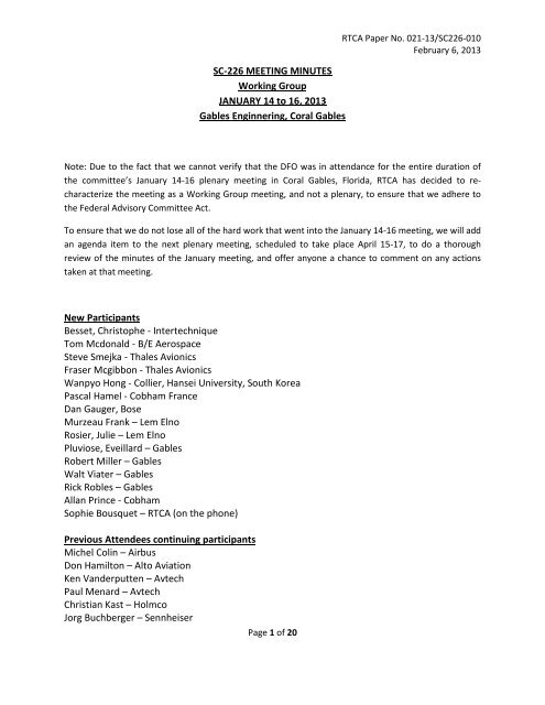
<strong>SC</strong>-<strong>226</strong> <strong>MEETING</strong> <strong>MINUTES</strong><br />
<strong>Working</strong> <strong>Group</strong><br />
<strong>JANUARY</strong> <strong>14</strong> to 16, 2013<br />
Gables Enginnering, Coral Gables<br />
<strong>RTCA</strong> Paper No. 021-13/<strong>SC</strong><strong>226</strong>-010<br />
February 6, 2013<br />
Note: Due to the fact that we cannot verify that the DFO was in attendance for the entire duration of<br />
the committee’s January <strong>14</strong>-16 plenary meeting in Coral Gables, Florida, <strong>RTCA</strong> has decided to recharacterize<br />
the meeting as a <strong>Working</strong> <strong>Group</strong> meeting, and not a plenary, to ensure that we adhere to<br />
the Federal Advisory Committee Act.<br />
To ensure that we do not lose all of the hard work that went into the January <strong>14</strong>-16 meeting, we will add<br />
an agenda item to the next plenary meeting, scheduled to take place April 15-17, to do a thorough<br />
review of the minutes of the January meeting, and offer anyone a chance to comment on any actions<br />
taken at that meeting.<br />
New Participants<br />
Besset, Christophe - Intertechnique<br />
Tom Mcdonald - B/E Aerospace<br />
Steve Smejka - Thales Avionics<br />
Fraser Mcgibbon - Thales Avionics<br />
Wanpyo Hong - Collier, Hansei University, South Korea<br />
Pascal Hamel - Cobham France<br />
Dan Gauger, Bose<br />
Murzeau Frank – Lem Elno<br />
Rosier, Julie – Lem Elno<br />
Pluviose, Eveillard – Gables<br />
Robert Miller – Gables<br />
Walt Viater – Gables<br />
Rick Robles – Gables<br />
Allan Prince - Cobham<br />
Sophie Bousquet – <strong>RTCA</strong> (on the phone)<br />
Previous Attendees continuing participants<br />
Michel Colin – Airbus<br />
Don Hamilton – Alto Aviation<br />
Ken Vanderputten – Avtech<br />
Paul Menard – Avtech<br />
Christian Kast – Holmco<br />
Jorg Buchberger – Sennheiser<br />
Page 1 of 20
<strong>RTCA</strong> Paper No. 021-13/<strong>SC</strong><strong>226</strong>-010<br />
February 6, 2013<br />
Christian Grone – Sennheiser<br />
Anthony Mangiameli – Bose<br />
Gregory Laborde – Cobham (not in attendance)<br />
Francesco Orsino – Gables Engineering<br />
Don Nault – Boeing<br />
Mark Goldberg - Honeywell<br />
Todd Blackstock – AEM<br />
Steven Parker – Bosch Security System<br />
Marchus Schmitz – Becker Avionics (not in attendance)<br />
Greg Sherwood – Garmin (not in attendance)<br />
Greg Frye – FAA (on the phone)<br />
First item of discussion: Pink Noise. Paul Menard - Avtech<br />
Suggestion to add reference to IEC60065 in the definitions section of the standard as a “recommended<br />
definition of pink noise”<br />
As part of the General Test Conditions for audio, IEC60065 section 4.1.6 states “Where relevant, a<br />
standard signal consisting of PINK NOISE, band-limited by a filter whose response conforms to that given<br />
in figure C.1 in annex C.” IEC60065 Figure C.1 from annex C is shown below.<br />
Second item of discussion: RF Susceptibility, Rick Robles - Gables<br />
Gables offered language addressing for Section 20 allowance for special instances where “in-band” RF<br />
threat signals can cause noise beyond the required threshold for the equipment performance similar to<br />
the allowance in Section 2.5.10 and 2.5.11 of the current DO-2<strong>14</strong> standard.<br />
Honeywell mentioned that they test the threat level to determine that there are no operational failures<br />
or system state changes as a result of the full threat level being applied. DO-2<strong>14</strong> allows the threat signal<br />
to be lowered to 2V/M when the threat signal generates too much audio noise.<br />
Example: The Category S definition is the ambient RF environment in the aircraft. There already<br />
has been a precedence set by DO160 to use Category S to pass RF MOPS. This should also be the<br />
Category used to pass the signal to noise audio MOPS.<br />
Airbus mentioned that they had an instance where a CAM was made non-functional by a GSM RF signal<br />
installed on the aircraft. ED112 now requires a minimum threat level of 20V/M as a minimum<br />
allowance.<br />
Boeing will discuss a possible solution with Gables and get back to us.<br />
Completed discussion of Gables paper. Proposed language was provided to Boeing to review.<br />
Page 2 of 20
<strong>RTCA</strong> Paper No. 021-13/<strong>SC</strong><strong>226</strong>-010<br />
February 6, 2013<br />
Third item of discussion: RF Susceptibility test levels and parasitic oscillation definition, Scott Moore -<br />
Jupiter Avionics<br />
The DO-2<strong>14</strong> Sec 2.5.11.2 Sustained Ambient RF Test (Radiated and Conducted) requires<br />
changes to the frequencies and levels used during the audio noise without signal test. However<br />
there is no clear instruction regarding which modulation to apply during the exposure.<br />
My other suggestion is for 2.8.2.2.1 Audio Frequency Response. It would be beneficial to have a<br />
definition of what a "parasitic oscillation" is, or change the requirement such that a standard and<br />
measurable audio attribute is referred to.<br />
Committee discussion identified that DO-160 includes the specified modulation frequency and level as<br />
well as the RF threat signal levels and frequencies. 20.4 paragraph (e) and 20.5 paragraph (e) both<br />
define the modulation frequency and level.<br />
The committee also agreed that it is true that parasitic oscillation was not well defined.<br />
The definitions section was revised to change Spurious Signals to Spurious/Parasitic Signals.<br />
Committee review of the definitions section found that the existing definition adequately covers the<br />
definition of “parasitic”.<br />
Other sections that referred ambiguously to oscillations in the form of “unwanted” oscillations were<br />
revised to include “parasitic” where applicable.<br />
Fourth item of discussion: ANR performance testing requirements, Anthony Mangiamelli and Dan<br />
Gauger - Bose<br />
Bose offered a paper regarding performance testing of headsets, relative to problems with<br />
characterizing performance around the 1KHz center as is currently done. Using the 1KHz center is found<br />
not effective or consistent and does not reflect human speech perception. A graph offered by Bose<br />
illustrates the actual performance.<br />
Bose proposes requiring a wide band performance test rather than a discrete 1KHz test.<br />
Todd Blackstock – AEM inquired about a concern over cert authorities’ possible perception that the<br />
headset and audio system might be perceived not consistent with one another. A note can be added to<br />
address the equivalency of the 1KHz specified headset to the 1KHz center frequency use to characterize<br />
performance of the audio system.<br />
Page 3 of 20
<strong>RTCA</strong> Paper No. 021-13/<strong>SC</strong><strong>226</strong>-010<br />
February 6, 2013<br />
Another question was raised concerning whether the graph in the Bose paper takes into account the<br />
female voice. Bose will look into this.<br />
Bose offered to write some proposed language for the standard based on their paper. The other<br />
manufacturers participating agreed with the information proposed. The committee welcomed Bose’<br />
paper.<br />
Boeing and Airbus both agreed that with new language based on the paper by Bose, they will be able to<br />
select amongst varying manufacturer’s ANR headsets and have a consistent way to make a comparison<br />
between them, and thereby more easily certify the headsets for their aircraft without significant testing<br />
as was needed in the past.<br />
Bose also suggested that instead of using power as the input to test the headset, voltage should be used<br />
as active headsets no longer have the same impedance as passive headsets. Input power is less<br />
important when an active circuit is connected in between the input and the speaker. A consistent input<br />
voltage is deemed to have more value for both passive and active applications.<br />
Bose will also get with Sennheiser and Bosch to discuss all aspects of their paper to come to consensus<br />
prior to returning to the next meeting with their recommended language.<br />
They will also address how to insure that ANR headset meet the same DO-160 audio performance<br />
requirements from DO-2<strong>14</strong> section 2.5 as are required by other microphones.<br />
Participants responsible for headsets (ANR and passive) work are:<br />
Anthony Mangiameli – Bose<br />
Dan Gauger, Bose<br />
Steven Parker – Bosch<br />
Jorg Buchberger – Sennheiser<br />
Christian Grone – Sennheiser<br />
Christian Kast – Holmco<br />
Fifth item of discussion: EASA Deviations<br />
EASA deviation paper ETSO.DevP.52d.pdf (Deviations requests #52 for an ETSO approval for CS-ETSO<br />
applicable to Headsets, Speakers and Aircraft Microphones (ETSO-C57a, C58a) Consultation Paper)<br />
should also be addressed as part of the headset working group’s efforts on how to best measure<br />
sensitivity. Current language in the standard is as follows:<br />
2.3.3.1 Headsets and Handsets<br />
When tested in accordance with the test procedure of subparagraph 2.7.2.1a,<br />
each ear phone shall have a sensitivity of 90 ±5 dB SPL (re: 20 uPa) with<br />
an input power level of 1 mW (RMS). A volume control may be provided to<br />
Page 4 of 20
<strong>RTCA</strong> Paper No. 021-13/<strong>SC</strong><strong>226</strong>-010<br />
February 6, 2013<br />
meet this requirement.<br />
below 75 dB SPL.<br />
However, it shall not be possible to reduce the level<br />
Language in the EASA deviation paper is as follows:<br />
To allow better harmonisation with the used side tone adjustments industry has received demands from<br />
operators to increase the output sound pressure to values above 95 dB (re: 20 µPa) when providing 1<br />
mW (RMS) to the headset or handset. Today technology allows providing higher sound pressure levels<br />
out of 1 mW (RMS) without producing distortions……..<br />
ETSO-C57a#7 – Headsets and Speakers<br />
Deviate from <strong>RTCA</strong> DO-2<strong>14</strong> 2.3.3.1 and provide a higher Sound Pressure Level (SPL) of 90 -5/+18 dB<br />
instead of 90 +/- 5 dB SPL (re: 20 µPa) out of 1 mW (RMS) input signal……<br />
Action has been given to the headset working group to complete by April 2013. Proposal based on EASA<br />
deviation paper is to study changing the headphone sensitivity tolerance from +/- 5dB to +8/-5dB. The<br />
working group will study and bring back their recommendation to the group.<br />
6 th item of discussion: Oxygen mask mic performance testing requirements, Murzeau Frank – Lem Elno<br />
and Rosier, Julie – Lem Elno<br />
Discussion around characterizing the performance of oxygen mask microphones while installed in the<br />
oxygen mask. The oxygen mask microphone can be understood to include the mask assembly, the<br />
microphone installed inside the mask assembly, and any circuitry that is included between the output of<br />
the microphone and the audio system. The mask, microphone and circuitry can be called the oxygen<br />
mask microphone system.<br />
Rosier offered a presentation addressing performance of oxygen mask microphones compared to DO-<br />
2<strong>14</strong>. Currently oxygen mask microphones are characterized according to the hand mic test<br />
requirements of DO-2<strong>14</strong>, without the microphone installed in the oxygen mask, and using the same<br />
couplers and equipment.<br />
The problem experienced by audio system designers and installers is that the output of the oxygen mask<br />
mic is often mismatched with other microphones that feed the same system so resistor padding must be<br />
applied in the installation to bring the oxygen mask microphone output level down to the same level as<br />
the other microphones.<br />
An artificial head was shown by Bose which, theoretically, could be used to test the oxygen mic when it<br />
is installed in the mask. But there does not exist any performance data on how the microphone<br />
performed when installed in the mask and therefore, the committee does not yet know how to<br />
performance requirements for the oxygen mask and oxygen mask mic when integrated together.<br />
Page 5 of 20
<strong>RTCA</strong> Paper No. 021-13/<strong>SC</strong><strong>226</strong>-010<br />
February 6, 2013<br />
Sixth item of discussion: Discussion of oxygen mask inhale mic cutoff (or attenuation) switch feature<br />
that exists on some masks.<br />
The FAA rule concerning continuous hot mic recording seems like it could preclude this option from<br />
being acceptable for certification. However, there is prior certification experience in the industry that<br />
has allowed these masks to be accepted on aircraft.<br />
Some information from the participants about who has certified the oxygen mask with the inhale cutoff<br />
switch, and on what type of aircraft, would be useful to the committee to use as reference information.<br />
Greg Frye, FAA, has taken the action to ask around concerning the FAA’s position on the cutoff switch.<br />
However, regardless of the outcome of this research, he suggested that we should cover this feature<br />
within section 1 of the standard. Due to past involvement of NTSB in developing the rule, it would be<br />
beyond the scope of the committee to include a hardened requirement for it.<br />
Language within the rule includes the word “uninterrupted” and this would be taken by the FAA to<br />
mean that no interruption of CVR hot mic audio can occur.<br />
The oxygen mask participants of the committee took the action to obtain an artificial head and collect<br />
usable test data from oxygen mask mic testing that will enable the committee to add requirements to<br />
the standard. This action will be completed prior to the April meeting.<br />
A frequency response versus sensitivity performance graph would be an additional and useful outcome<br />
of the oxygen mask performance characterization work.<br />
Another issue that should be considered by the oxygen mask working group is related to the cord<br />
connector flexibility test requirements. The requirements in the current DO-2<strong>14</strong> standard to not apply<br />
in the say way to the oxygen mask microphone cord because the cord is mechanically routed in parallel<br />
with the oxygen mask hose. The hose prevents the same kind of torsion and pull forces from being<br />
applied to the cord. An appropriate test needs to be defined for the oxygen mask cord and connector.<br />
Participants responsible for oxygen mask microphone system work are:<br />
Murzeau Frank – Lem Elno<br />
Rosier, Julie – Lem Elno<br />
Tom Mcdonald - B/E Aerospace<br />
Besset, Christophe – Intertechnique<br />
Christian Kast – Holmco<br />
All other microphones covered by the current standard include specific sections for the type of<br />
microphone (e.g. hand mic, boom mic, etc.) . The oxygen mask mic system similarly should be<br />
addressed by its own sections within the revised standard.<br />
See also, EASA deviation paper is ETSO.DevP.44.pdf below.<br />
The EASA deviation paper is ETSO.DevP.44.pdf and will be uploaded on the <strong>RTCA</strong> sharepoint site for the<br />
working group’s review and consideration.<br />
Page 6 of 20
<strong>RTCA</strong> Paper No. 021-13/<strong>SC</strong><strong>226</strong>-010<br />
February 6, 2013<br />
<strong>SC</strong><strong>226</strong> committee response:<br />
The oxygen mask working group should also consider the EASA deviation request related to frequency<br />
response modification from the current DO-2<strong>14</strong> standard requirements.<br />
Seventh item of discussion: Discussion “HOT MIC” definition within the standard, Michel Colin, Airbus<br />
Michel noted that the standard should define the term “HOT MIC” (e.g. the MIC to CVR audio path<br />
through the audio system).<br />
The ED112 definition can be used.<br />
Michel Collin, Airbus, submitted the following language originating from ED112:<br />
Hereunder the definition of Hot-mic from ED 56A:<br />
The CVR 'HOT' Microphone:<br />
The hot-microphone ensures that, in addition to the recording of the radio transmissions to and from the aircraft,<br />
all sounds received by the crew's microphones are recorded continuously irrespective of the position of the audio<br />
selector switches. The volume control has no effect on the level of recording of the hot-microphone. A minor<br />
interface change provides the hot-microphone feature by summing each crew member's microphone signal with<br />
the telephone signal.<br />
The CVR itself is not affected by implementation of this concept.<br />
And a precision given by ED 112:<br />
Each CVR should be installed so as to provide with reference to a timescale, simultaneous recordings of:<br />
i. voice communications transmitted from or received in the cockpit by radio,<br />
ii. the aural environment of the cockpit,<br />
iii. the audio signals received from each boom and mask microphone in use, without interruption,<br />
8th item of discussion: Audio Noise Without Signal and Listening Test during DO-160x Section 8<br />
vibration.<br />
Todd Blackstock, AEM, pointed out that DO-<strong>14</strong>3 for Marker Beacons allows a relaxed noise requirement<br />
during vibration. Additional vibration test data taken from a system tested by Cobham determined that<br />
at some resonant frequencies, noise levels during vibration can reach 30 dB below rated power.<br />
Honeywell also reviewed their test data and confirmed similar results from testing they had performed.<br />
For audio systems, a noise and listening test should be included because problems with noise have been<br />
observed, such as due to microphonics. The noise level can similarly be relaxed from the 50 dB below<br />
rated power requirement from Section 2.4 because the ambient acoustic noise background is also<br />
elevated during the test, and during normal operation of the system in its operating environment. Thus<br />
Page 7 of 20
<strong>RTCA</strong> Paper No. 021-13/<strong>SC</strong><strong>226</strong>-010<br />
February 6, 2013<br />
a relaxed noise requirement will not incumber intelligibility. The following language is being added to<br />
section 2.5.5 (c).<br />
(2) Subparagraph 2.4.11.1 - Audio Noise Without Signal<br />
(3) Paragraph 2.4.15 - Listening Test<br />
The equipment shall be subjected to the test conditions, as specified<br />
in <strong>RTCA</strong>/DO-160x, Section 8 .0. Exception: The following test level shall<br />
apply:<br />
For Audio Noise Without Signal, when tested in accordance with the test<br />
procedures in subparagraph 2.8.2.11.1, the level of the noise output of the<br />
system shall be at least 30 dB below the rated output of the system.<br />
9th item of discussion: EASA deviations<br />
Deviations reviewed:<br />
EASA Deviation ETSO.DevP.17.pdf (Deviations requests #17 for an ETSO approval for CS-ETSO applicable<br />
to C57a (Headsets and Speakers) Consultation Paper)<br />
EUROCAE ED-18 specifies:<br />
Using the resistor substitution method, the equipment impedance at 1000 Hz shall be<br />
within ± 20% of the manufacturer’s rated impedance, which shall be between the limits<br />
of 150 Ωand 600 Ω<br />
Note<br />
Some general aviation avionics equipment may require the use of headsets with only<br />
600 Ω impedance.<br />
Use of lower impedance headsets could result in damage to such avionics equipment.<br />
Therefore, headsets which have an earphone circuit impedance other than 600 Ω± 20%<br />
shall include in their installation instructions a caution stating the following:<br />
“Damage could occur to avionics equipment by the use of these headsets if the<br />
equipment was manufactured for use with only 600 Ω headsets. If in doubt, consult the<br />
avionics equipment manufacturer.”<br />
Page 8 of 20
<strong>RTCA</strong> Paper No. 021-13/<strong>SC</strong><strong>226</strong>-010<br />
February 6, 2013<br />
Industry:<br />
Some aircraft manufacturers require headsets with impedance that shall be between the<br />
limits of 8 Ω and 32 Ω± 20%.<br />
An equivalent level of safety is provided limiting the use of headsets with low impedance<br />
in the aircraft or helicopters that require low impedance.<br />
<strong>SC</strong><strong>226</strong> committee response:<br />
The committee has addressed the use of 8 ohm and 50 ohm (representative of multiple 150 ohm)<br />
headsets connected in parallel. 8 ohm is now considered within the revised standard as “low<br />
impedance”, 600 ohm is now considered “high impedance” and 150 ohm is considered “commercial<br />
aviation impedance” headsets.<br />
The committee knows of no application of 32 ohm headsets being used in cockpit communication<br />
applications. 32 ohm headsets that the committee is aware of are typically consumer style headsets<br />
such as those used in the airline passenger cabin for music listening purposes, or those sold on the<br />
consumer market for IPOD music players. As such, 32 ohm headsets are not deemed appropriate for<br />
coverage by the revised standards.<br />
On the subject of damage to equipment occurring due to the use of low impedance headsets on a<br />
system intended for high impedance headsets, the committee considers that the standard also has a<br />
requirement for a short circuit test that is intended to insure the equipment is protected against<br />
damage due to low impedances being inadvertently connected. However, the committee also considers<br />
that there could be legacy equipment still in use within aircraft that may not have been required to<br />
meet the short circuit test contained in previous standard DO-170 or current standard DO-2<strong>14</strong> and as<br />
such, the note below DO-2<strong>14</strong> section 2.3.5.2 still applies. Note as follows:<br />
Some general aviation avionics equipment may require the use of headsets with 600 Ω impedance only. Use of lower<br />
impedance headsets could result in damage to such equipment. Therefore, headsets which have an earphone circuit impedance<br />
other than 600 Ω ±20% shall include in their installation instructions a caution stating the following: "Damage could occur<br />
to avionics equipment by the use of these headsets if the equipment was manufactured for use with 600 Ω headsets only-if in<br />
doubt, consult the avionics equipment manufacturer."<br />
EASA deviation ETSO.DevP.27.pdf Deviations requests ETSO.Dev.P027 for an ETSO approval for CS-<br />
ETSO applicable to Headset including Microphone (ETSO-C57a, C58a) Consultation Paper<br />
<strong>SC</strong><strong>226</strong> committee response:<br />
To address headset cord connector pull out the following note has been added to the standard section<br />
2.2.8.3 and 2.3.8.4:<br />
Note: The earpiece-cord fastening for the headset will be subject to less amount of steady pull<br />
as the headset is not fixed at the head and the headset is not connected to a fixed mounted panel.<br />
Page 9 of 20
<strong>RTCA</strong> Paper No. 021-13/<strong>SC</strong><strong>226</strong>-010<br />
February 6, 2013<br />
Due to the reduced strains and weight of the earpiece, Therefore the maximum pulling load of<br />
1.0 kg shall be applicable for the earpiece – cable interface.<br />
EASA deviation ETSO.DevP.56c.pdf Deviation request #56 for an ETSO approval for CS-ETSO applicable<br />
to Aircraft Microphones (ETSO- C58a) Consultation Paper – Christian Kast, Holmco<br />
Added section 2.2.2.3 to address the EASA deviation allowing 3.5dB output increase instead of 5dB<br />
required for all other microphones based on testing done by Holmco and submitted and approved by<br />
EASA.<br />
2.2.2.3 Handset Microphone<br />
When tested in accordance with the test procedure in subparagraph 2.6.2.3, the<br />
total harmonic distortion contributed by the microphone shall not exceed five<br />
percent over the frequency range of 350 to 6000 Hz at a sound pressure input of<br />
1<strong>14</strong> dB SPL (re: 20 pPa). Increasing the sound pressure input by 6 dB must yield<br />
an output increase of at least 3.5 dB.<br />
DO-160x references issues: Todd Blackstock – AEM<br />
We have previously changed all references to DO-160C to DO-160x. Todd Blackstock has re-reviewed<br />
the edited standard and found additional references to specific subparagraphs within DO-160C that are<br />
still referenced. Specific subparagraph numbers within DO-160C should not be referenced in the<br />
revised standard because DO-160 is revised so often and specific subparagraph numbers could change.<br />
The consensus is that we can use the section title and major section number (e.g. 16.0) from DO-160 as<br />
a more reliable reference since these are less likely to change as new revisions of DO-160 are produced<br />
in the future. Additional references within the standard, to specific categories from DO-160 need to be<br />
reviewed and edited as appropriate as well. Highlighted below.<br />
2.4.11.1 Audio Noise Without Signal<br />
When tested in accordance with the test procedures in subparagraph 2.8.2.11.1,<br />
the level of the noise output of the system shall be at least 50 dB below the<br />
rated output of the system for Category A and B and 60 dB for Category Z<br />
(<strong>RTCA</strong>/DO-160x Definitions, Subsection 19.2).<br />
2.5.1 Temperature and Altitude Tests<br />
<strong>RTCA</strong>/DO-160x contains several temperature and altitude test procedures that<br />
are specified according to equipment category. These categories are included<br />
in Subsection 4.3 of <strong>RTCA</strong>/DO-160x. The following subparagraphs<br />
contain the applicable test conditions specified in Section 4.0 of <strong>RTCA</strong>/DO-<br />
160x.<br />
Page 10 of 20
<strong>RTCA</strong> Paper No. 021-13/<strong>SC</strong><strong>226</strong>-010<br />
February 6, 2013<br />
2.5.6 Magnetic Effect Test<br />
a. Aircraft Microphones (except Carbon):<br />
During the test, the following requirements shall be met:<br />
The requirements of the appropriate <strong>RTCA</strong>/DO-160x category.<br />
It is recommended that microphones intended for use in the cockpit,<br />
should meet the requirements of categories Z and A. It is strongly recommended<br />
that a cautionary note citing possible effects to magnetic compasses, be<br />
packed with microphones meeting requirements other than Class Z.<br />
b. Aircraft Headsets, Handsets and Loudspeakers:<br />
During the test, the following requirements shall be met:<br />
The requirements of the appropriate <strong>RTCA</strong>/DO-160x<br />
category.<br />
It is recommended that headsets and handsets intended for use in<br />
the cockpit, should meet the requirements of categories Z and A.<br />
It is strongly recommended that a cautionary note citing possible<br />
effects to magnetic compasses, be packed with headsets and handsets<br />
meeting requirements other than Class Z.<br />
STANDARD<br />
NORMAL OPERATING CONDITIONS<br />
MINIMUM SUPPLY<br />
VOLTAGE<br />
EMERGENCY SUPPLY<br />
VOLTAGE<br />
Rated Power<br />
-3 dB<br />
REF: 0 dB = Rated Power<br />
in Paragraph 2.4.2<br />
-6 dB<br />
REF: 0 dB = Rated<br />
Power in Paragraph 2.4.2<br />
Distortion 20% 30%<br />
No Signal Noise<br />
-50 dB Cat. A & B<br />
-60 dB Cat. Z<br />
-40 dB Cat. A & B<br />
-40 dB Cat. Z<br />
Listening Test Intelligible Intelligible<br />
TABLE 2-1 TABULATION OF REQUIREMENTS FOR POWER INPUT<br />
TEST<br />
Page 11 of 20
<strong>RTCA</strong> Paper No. 021-13/<strong>SC</strong><strong>226</strong>-010<br />
February 6, 2013<br />
Todd Blackstock reviewed the categories called out in the standard and determined that the categories are still<br />
applicable. Section 1.8 has been revised as follows:<br />
1.8 Test Procedures<br />
The test procedures…………<br />
a. Environmental Tests<br />
Environmental test requirements are specified in Subsection 2.5. The<br />
procedures and their associated limit requirements are intended to<br />
provide a laboratory means of determining the electrical and mechanical<br />
performance of the equipment under environmental conditions expected to<br />
be encountered in actual operations. Unless otherwise specified, the<br />
environmental conditions and test procedures contained in <strong>RTCA</strong>/DO-<br />
160x, whereas DO-160x refers to the latest version of DO-160 or as<br />
previously agreed with the administrator, Environmental Conditions and<br />
Test Procedures for Airborne Equipment, will be used to demonstrate<br />
equipment compliance. Within section 2.5 of this document, the relevant<br />
subsection titles are from DO-160G and referred to in each subsection of<br />
section 2.5. In the event that future revisions of DO-160x result with the<br />
referenced subsections being renamed, the closest equivalent subsection<br />
should be used for compliance with section 2.5 of this document.<br />
Discussion of microphone performance testing under DO-160 test conditions:<br />
Many tests require performance testing under DO-160 conditions after the test.<br />
Altitude was raised as a problem. Members of the committee do not know of any artificial voice<br />
equipment that is calibrated under altitude conditions so the source of the signal can be said to have<br />
unknown performance quality under the test conditions.<br />
DO-2<strong>14</strong> requires tests to be performed during exposure to altitude. The question posed, is how to<br />
insure that the performance is known and correct under the test condition.<br />
2.5.1.4 Altitude Tests<br />
The equipment shall be subjected to the test conditions as specified<br />
in <strong>RTCA</strong>/DO-160x, Section 4.0<br />
a. Aircraft Microphones (except Carbon):<br />
During the test, the following requirements shall be met within ±6<br />
dB: (1) Paragraph 2.2.1 Frequency Response<br />
Page 12 of 20
<strong>RTCA</strong> Paper No. 021-13/<strong>SC</strong><strong>226</strong>-010<br />
February 6, 2013<br />
(2) Paragraph 2.2.3 Sensitivity<br />
Sennheiser offered to check with company physicists to determine what the theoretical performance of<br />
their microphones under low pressure conditions would be expected to be.<br />
B/E Aerospace can coordinate test activities to try to determine what the effect on the acoustic source<br />
and the microphone under test would be under altitude conditions.<br />
The same issues pertain to Temperature and Temperature Variation except that the test specifically<br />
refers to the microphone preamplifier (independently of the microphone?). The committee had a range<br />
of interpretations.<br />
2.5.2 Temperature Variation Test<br />
The equipment shall be subjected to the test conditions as specified<br />
in <strong>RTCA</strong>/DO-160x, Section 5.0.<br />
a. Aircraft Microphones (Except Carbon):<br />
The microphone preamplifier, as a component of the microphone<br />
assembly shall be subjected to this test. During the test, the following<br />
requirements shall be met:<br />
(1) Subparagraph 2.2.2.1 Distortion Characteristics<br />
(2) Subparagraph 2.2.3.1 Sensitivity<br />
Bosch offered to check with the test equipment manufacturer to determine what the performance of<br />
the artificial voice would be expected to be under temperature and temperature variation test<br />
conditions.<br />
Additional question: Why are the Aircraft Headsets, Handsets and Loudspeakers excluded from the<br />
temperature variation test. Bosch, Sennheiser and Bose were asked to check with their engineering<br />
departments to determine a valid reason.<br />
Discussion on RF Interference and 2V/M relaxed noise allowance in Section 2.5.11.<br />
Another issue is the title of “sustained ambient” and “transient”. These do not align with the current<br />
version of DO-160.<br />
The “sustained ambient” and “transient” sections should be combined into one.<br />
Radio Frequency Susceptibility Test (Radiated and Conducted)<br />
Page 13 of 20
<strong>RTCA</strong> Paper No. 021-13/<strong>SC</strong><strong>226</strong>-010<br />
February 6, 2013<br />
This section is partitioned into two subsections. The first deals with short duration exposure to<br />
transient radiated fields. The second deals with sustained ambient lower intensity radiated<br />
fields. The requirements of both subsections must be met.<br />
Transient RF Test (Radiated and Conducted)<br />
The equipment shall be subjected to<br />
<strong>RTCA</strong>/DO-160x, Section 20.0.<br />
the test conditions, as specified in<br />
a. Aircraft Microphones (except Carbon):<br />
During the test, the following requirements shall be met:<br />
The recovered modulation shall not be more than 10 mV RMS.<br />
NOTE:<br />
The microphone should survive the test, fully recover<br />
following the test, and should not cause any unsafe<br />
condition in system operation during the test.<br />
b. Aircraft Headsets, Handsets and Loudspeakers:<br />
NOTE: Any headset or handset containing active components should<br />
not generate acoustic levels that may interfere with safe<br />
operation of the aircraft.<br />
c. Audio System:<br />
During the test, the following requirements shall be<br />
met: Paragraph 2.4.15 - Listening Test<br />
NOTE: The test shall not cause any interruption in communication<br />
as determined by the listening test. Degradation of signal<br />
quality is acceptable as long as the signal remains adequate<br />
for communications. Furthermore, system state changes<br />
(such as system resets, configuration changes, volume level<br />
changes, etc.) shall not occur.<br />
2.5.11.2 Sustained Ambient RF Test (Radiated and Conducted)<br />
The equipment shall be subjected to the test conditions, as specified<br />
in <strong>RTCA</strong>/DO-160x, Section 20.0. Exception: The following test levels and<br />
frequencies shall apply:<br />
Page <strong>14</strong> of 20
<strong>RTCA</strong> Paper No. 021-13/<strong>SC</strong><strong>226</strong>-010<br />
February 6, 2013<br />
For Radiated Susceptibility: The level shall be 2 V/m at the frequency range<br />
specified within the applicable category in DO-160x.<br />
Note: DO-307 covers Radiated RF Interference considerations for<br />
Transmitting Portable Electronic Devices (PEDs). RF Interference from PEDs<br />
devices can interfere with functions of the audio system. Audio System<br />
components are only exposed to PEDs RF Interference when the Audio System<br />
component is located in an area of the aircraft near the PEDs devices and when<br />
there is no metal shielding between the audio system component and the PEDs<br />
devices. As a result, it is reasonable for only the exposed audio equipment to be<br />
tested according to the requirements of DO-307. Additionally, when equipment<br />
is mounted so that a portion of the equipment is shielded, it is reasonable for<br />
only the exposed side(s) of the audio equipment to be exposed during the PEDs<br />
RF Interference testing. An analysis should be used to describe the rationale<br />
for the manner in which the equipment under test is exposed.<br />
Discussion of problems experienced by members of the committee with regard to current test<br />
requirements calling for the conducted RF frequency sweep to start at 10KHz.<br />
Experience of the participants has found that even when the 10KHz RF signal is applied with no<br />
modulation, it can often be heard over the audio system. 10KHz is very close to the audio frequency<br />
band of interest for the audio system. The audio system is typically composed of a large number audio<br />
inputs and outputs, all of which must be filtered to remove RF. However, with the RF starting<br />
frequency so close to the audio frequency band, the filters must be more effective, more complex,<br />
require more components, and occupy more space within the equipment enclosure in order to be<br />
effective enough to remove 10 KHz RF noise. As a practical matter, such a design will be<br />
mathematically less reliable, and the committee questions why the RF frequency should start at such a<br />
low frequency when there are no sources of this type on board the aircraft. The consensus was that<br />
the starting frequency should start at a frequency just beyond the maximum audio frequency band<br />
discernible by human hearing (e.g. >20 KHz). 24 KHz was chosen as the new starting frequency. The<br />
language in the standard was edited as follows for conducted RF susceptibility testing.<br />
For Conducted Susceptibility: The level shall be 3 mA (2 V/m) from 500 kHz to<br />
400 MHz, and from 500 kHz to 24 kHz shall fall at the rate of 6 dB per octave (20 dB per<br />
decade).<br />
Don Nault, Boeing took the action to check with his compliance personnel at Boeing to determine if the note is<br />
acceptable.<br />
Discussion on fire protection. TSO-C57a and TSO-C58a used to include a requirement similar to as follows from<br />
DO-2<strong>14</strong> but no longer do and this sometimes causes problems for Boeing when equipment is not tested to Part 25<br />
Appendix F.<br />
2.1.4 Fire Protection<br />
Page 15 of 20
<strong>RTCA</strong> Paper No. 021-13/<strong>SC</strong><strong>226</strong>-010<br />
February 6, 2013<br />
All materials used shall be self-extinguishing except for small parts (such<br />
as knobs, fasteners, seals, grommets and small electrical parts) that would not<br />
contri bute significantly to the propagation of a fire.<br />
NOTE: One means of showing compliance is contained in Federal<br />
Aviation Regulations (FAR), Part 25, Appendix F.<br />
The committee decided that there are many means used (and allowed by the note above) to comply<br />
with the fire protection requirement. The section should be remain worded as is.<br />
Discussion of headsets, handsets and loudspeakers that are connected to aircraft power. The<br />
committee identified the subsections within section 2.5 of the standard that will have to include new<br />
performance requirements for headsets, handsets and loudspeakers that are connected to aircraft<br />
power. The effected sections have been tagged “TBD” in the draft standard as noted below. The output<br />
of the headset working group’s actions should provide guidance of what performance tests are required<br />
for the effected sections.<br />
Applicable to headsets, handsets and loudspeakers utilizing aircraft power,<br />
During the test, the following requirements as modified in Table 2-1 shall be met: TBD<br />
A previous temporary comment was included in the draft standard left open the text of the test<br />
procedure for the PTT delay test. A reference was added to new paragraph 2.8.2.13.3 within 2.4.13.3<br />
added during a previous committee meeting.<br />
2.4.13.3 Push to Talk (PTT) Delay<br />
From the time that the PTT input to the system is activated, the system shall produce a PTT at the<br />
system output within a period of 100 milliseconds when tested in accordance…….. with<br />
subparagraph 2.8.2.13.3<br />
Section 2.8.2.13.3 is also now added:<br />
2.8.2.13.3 Push to Talk (PTT) Delay<br />
a. Apply a 0.1 Hz square wave signal from an open/ground signal souce to the PTT input of the<br />
equipment while monitoring the PTT input signal with an oscilloscope.<br />
b. Monitor the PTT output of the equipment with a second channel of the oscilloscope and<br />
measure the time difference between the PTT input and PTT output signals.<br />
c. Repeat for dissimilar input/output combinations.<br />
Page 16 of 20
<strong>RTCA</strong> Paper No. 021-13/<strong>SC</strong><strong>226</strong>-010<br />
February 6, 2013<br />
Discussion of DO-160x, DO-178x and addition of reference to DO-254. Need to address adding a<br />
reference to DO-254 within the standard and as follows:<br />
Remove ‘x’ from DO-160 and DO-178 references within the draft standard to make the references<br />
cleaner. Edit the DO-160 and add reference to DO-178 and DO-254 to generic revision reference note to<br />
reflect removal of ‘x’. The note could be stated to reference the base document number with no rev.<br />
Discussion with headset manufactures pointed out that 300 ohm single sided headsets exist presently.<br />
Section 1.5.5(b) needs to include the following medium impedance headset impedance:<br />
Medium Impedance Headset<br />
300 Ω ± 20% nominal across the frequency range.<br />
All sections referencing headset impedances need to be harmonized to insure that they all reflect the<br />
same list of impedances, headset output loads and tolerance callouts where applicable.<br />
There are also still references to 150 to 600 ohms. 300 ohm medium impedance headsets (mono or<br />
stereo) fit between 150 and 600 ohms. But these need to be revised to also include 8 ohm low<br />
impedance.<br />
Also need to review microphone impedances and tolerances and insure they are harmonized throughout<br />
the standard. 1.5.3 in DO-2<strong>14</strong> still references 250mV, whereas 2.2.3 now references 400mV with 1<strong>14</strong>dB<br />
SPL input to be consistent with ARINC538. 400mV with 1<strong>14</strong>dB is the preferred specification.<br />
Discussion about problems managing the large number of headset impedances available on the market.<br />
Consensus was that standardizing on a single impedance headset is desirable and that a note within the<br />
standard would be helpful to guide industry in this direction in the future.<br />
Proposed language: It is highly desirable to for future applications to standardize on 150<br />
ohm mono (300 ohm stereo) headsets<br />
Pascal Hamel - Cobham France, has the action to perform a study of the impact of referencing a<br />
preferred impedance from the choices of 8 ohms, 150 ohms, 300 ohms or 600 ohms within the<br />
standard.<br />
Sennheiser offered the following comparative headset impedance information from various<br />
manufacturers for reference.<br />
Page 17 of 20
<strong>RTCA</strong> Paper No. 021-13/<strong>SC</strong><strong>226</strong>-010<br />
February 6, 2013<br />
DO 2<strong>14</strong> 2.3.4.1 150 Ohm 600 Ohm<br />
ARINC 535A 550 Ohm 650 Ohm<br />
Manufacturer Application 0 0 1 2 3 4 5 6 7 8 9 10 11 12 13<br />
Holmberg Commercial 550 Ohm<br />
Holmberg Commercial 560 Ohm<br />
Holmberg Commercial 570 Ohm<br />
Sennheiser HMEC 26 Commercial 600 Ohm 1200 Ohm<br />
Sennheiser HMEC 46 Commercial 600 Ohm 1200 Ohm<br />
Telex Airman 750 Commercial 150 Ohm 300 Ohm 600 Ohm<br />
Telex Airman 850 Commercial 150 Ohm 300 Ohm 600 Ohm<br />
Telex Ascend Commercial 600 Ohm<br />
Plantronics MS 260 Commercial 600 Ohm<br />
Beyerdynamic HS400 GA 210 Ohm 270 Ohm<br />
Beyerdynamic HS800 GA 260 Ohm 560 Ohm<br />
Bose A 20 GA 160 Ohm 320 Ohm<br />
Bose X GA 160 Ohm 320 Ohm<br />
Peltor 8003 GA 165 Ohm 330 Ohm<br />
Peltor 8006 GA 165 Ohm 330 Ohm<br />
S1 DIGITAL GA 180 Ohm 360 Ohm<br />
S1 PASSIVE GA <strong>14</strong>0 Ohm 280 Ohm<br />
Sennheiser HMEC 460 GA 400 Ohm 600 Ohm<br />
Sennheiser HMEC 350 GA 300 Ohm 600 Ohm<br />
Sennheiser HME 110 GA 150 Ohm 300 Ohm<br />
Sennheiser HME 95 GA 225 Ohm 300 Ohm<br />
Telex 30XT GA 150 Ohm 300 Ohm<br />
Telex 50D GA 150 Ohm 300 Ohm<br />
David Clark X11 GA 225 Ohm 450 Ohm<br />
David Clark H10-13.4 GA 150 Ohm<br />
David Clark H10-13X GA 150 Ohm 300 Ohm<br />
Peltor 8103 Helicopter 16 Ohm 32 Ohm<br />
Page 18 of 20
<strong>RTCA</strong> Paper No. 021-13/<strong>SC</strong><strong>226</strong>-010<br />
February 6, 2013<br />
3.2.2Acoustic Output<br />
The acoustic output of the headset should be 100 dB, ref. 0.0002 dynes per square centimeter per 1.0<br />
milliwatt (0.5 mW per earphone) in the frequency range of 300 to 4000 Hz within the following limits:<br />
300 Hz ± 3 dB ref. 100 dB per 0.5 mW<br />
1000 Hz ± 1.5 dB<br />
4000 Hz ± 3 dB<br />
8000 Hz ± 10 dB or more<br />
Note: 100 dB per 0.5 mW is equivalent to 20 dynes per square<br />
centimeter per 0.5 mW, or 52 dynes per square cenitmeter<br />
per 1 volt.<br />
COMMENTARY<br />
The headset acoustic output should not exceed 100 dB per<br />
milliwatt because a desired signal-to-noise ratio of 46 dB requires<br />
that the system noise hum level be suppressed to a value below 4<br />
millivolts.<br />
Discussion of headset connectors. The committee discussed the benefits of the XLR-5 versus the XLR-7<br />
connector. The problem with XLR-5 is that it has too few pins to include DC-. As a result, DC – is often<br />
shared with the MIC return causing conducted audio frequency (400 Hz commonly) noise problems in<br />
the ANR headset audio.<br />
XLR-7 provides additional pins, not only for DC – but also includes a pin that can be used for headset<br />
stereo right. Headset stereo left can be dual use with headset mono HI.<br />
The Sennheiser white paper submitted at the July 2012 <strong>SC</strong><strong>226</strong> DO-2<strong>14</strong> committee meeting was<br />
referenced. The following language is proposed for the standard.<br />
3.3Plug (from ARINC535B draft)<br />
A single plug and cord should be provided for the microphone and headset. The plug should be an XLR-<br />
7 straight plug with the following pin connections:<br />
Pin 1 – Headset Hi/Left<br />
Pin 2 – Headset Lo<br />
Pin 3 – Mic pre-amp Hi<br />
Pin 4 – Mic pre-amp Lo<br />
Pin 5 - DC+<br />
Pin 6 - DC-<br />
Pin 7 - Headset Hi/Right<br />
Page 19 of 20
<strong>RTCA</strong> Paper No. 021-13/<strong>SC</strong><strong>226</strong>-010<br />
February 6, 2013<br />
The headset working group will need to analyze power supply input performance, current and any other<br />
parameters applicable to the active headset power pins and provide a recommendation to the<br />
committee.<br />
Future meeting dates:<br />
July week of 15 th -19 th (<strong>RTCA</strong> 15 th - 17 th and then ARINC 18 th and 19 th ) and October 1 st -4 th (<strong>RTCA</strong> 1 st and<br />
2 nd and then ARINC 3 rd and 4 th ).<br />
Proposed locations would be: April in DC, July in DC (or to be determined), October in DC (or to be<br />
determined).<br />
A suggestion was raised, for better European participation, that we try to hold a meeting in Germany in<br />
July. Sophie from <strong>RTCA</strong> will check to see if this is a possibility.<br />
ARINC meetings that follow <strong>SC</strong>-<strong>226</strong> meetings in Berlin Germany.<br />
Sophie from <strong>RTCA</strong> suggested that we release the document 45 days prior to PMC in December.<br />
Early October <strong>SC</strong><strong>226</strong> meeting will be held to finalize changes following FRAC (TOR says completion end<br />
of September (early October suffices).<br />
Need to discuss publication date for the new TSO at next session.<br />
Detailed agenda will need to be completed and posted on the share point site for completion of<br />
remaining activities in April, July, and October.<br />
Page 20 of 20