Download
Download
Download

You also want an ePaper? Increase the reach of your titles
YUMPU automatically turns print PDFs into web optimized ePapers that Google loves.
COVER FEATURE<br />
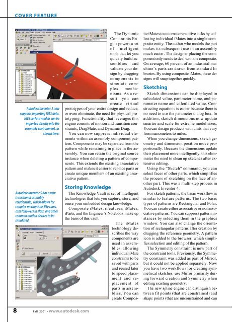
Autodesk Inventor 5 now<br />
supports importing IGES data.<br />
IGES surface models can be<br />
imported directly into the<br />
assembly environment, as<br />
shown here.<br />
Autodesk Inventor 5 has a new<br />
transitional assembly<br />
relationship, which allows for<br />
complex mechanisms like cams,<br />
cam followers in slots, and other<br />
common motion devices to be<br />
simulated.<br />
The Dynamic<br />
Constraints Engine<br />
powers a set<br />
of intelligent<br />
tools that let you<br />
quickly build assemblies<br />
and<br />
validate your design<br />
by dragging<br />
components to<br />
simulate complex<br />
mechanisms.<br />
As a result,<br />
you can<br />
create virtual<br />
prototypes of your entire design and reduce,<br />
or even eliminate, the need for physical prototyping.<br />
Functionality that leverages this<br />
engine consists of motion and transition constraints,<br />
DragMate, and Dynamic Drag.<br />
You can now suppress individual elements<br />
within an assembly component pattern.<br />
Components may be separated from the<br />
pattern while remaining in place in the assembly.<br />
You can retain the original source<br />
instance when deleting a pattern of components.<br />
This extends the existing associative<br />
pattern and makes it easier to replace parts or<br />
create unique members of an existing associative<br />
pattern.<br />
Storing Knowledge<br />
The Knowledge Vault is set of intelligent<br />
technologies that lets you capture, store, and<br />
reuse your embedded design knowledge.<br />
Composite iMates, iFeatures, iMates,<br />
iParts, and the Engineer’s Notebook make up<br />
the basis of this vault.<br />
The iMates<br />
technology describes<br />
the way<br />
components are<br />
used in assemblies,<br />
allowing<br />
individual iMate<br />
constraints to be<br />
saved with parts<br />
and reused later<br />
to speed placement<br />
and replacement<br />
of<br />
parts in assemblies.<br />
You can<br />
create Composite<br />
iMates to automate repetitive tasks by collecting<br />
individual iMates into a single composite<br />
entity. The author who models the part<br />
makes its subsequent use in an assembly<br />
much easier. The designer placing the component<br />
only needs to deal with the composite.<br />
On average, 60 percent of an industrial machine’s<br />
parts are drawn from standard libraries.<br />
By using composite iMates, these designs<br />
will snap together quickly.<br />
Sketching<br />
Sketch dimensions can be displayed in<br />
calculated value, parameter name, and parameter<br />
name and calculated value. Constructing<br />
equations is easier because there is<br />
no need to use the parameter dialog box. In<br />
addition, sketch dimensions now update<br />
smarter and scale for extreme model sizes.<br />
You can design products with units that vary<br />
from nanometers to miles.<br />
When you change dimensions, sketch geometry<br />
and dimension position move proportionally.<br />
Because the dimensions update<br />
their placement more intelligently, this eliminates<br />
the need to clean up sketches after extensive<br />
editing.<br />
Using the “Sketch” command, you can<br />
select faces of other parts, which simplifies<br />
the process of sketching on the face of another<br />
part. This was a multi-step process in<br />
Autodesk Inventor 4.<br />
For sketch patterns, the basic workflow is<br />
similar to feature patterns. The two basic<br />
types of patterns are Rectangular and Polar.<br />
You can create either associative or nonassociative<br />
patterns. You can suppress pattern instances<br />
by selecting them in the graphics<br />
window. You can also change the orientation<br />
of rectangular patterns after creation by<br />
dragging the reference geometry. A pattern<br />
icon is added to the browser, which simplifies<br />
selection and editing of the pattern.<br />
The Symmetry constraint is now part of<br />
the constraint tools. Previously, the Symmetry<br />
constraint was added as part of Mirror,<br />
but it could not be applied separately. Now<br />
you have two workflows for creating symmetrical<br />
sketches: use Mirror primarily during<br />
forward creation and Symmetry when<br />
editing existing geometry.<br />
The new spline engine can distinguish between<br />
fit points (that are constrained) and<br />
shape points (that are unconstrained and can<br />
8<br />
Fall 2001 • www.autodesk.com