30XA 252-1702
30XA 252-1702
30XA 252-1702

Create successful ePaper yourself
Turn your PDF publications into a flip-book with our unique Google optimized e-Paper software.
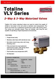
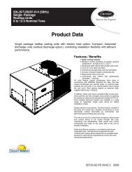
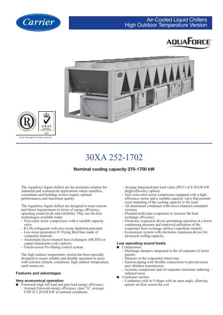
Air-Cooled Liquid Chillers<br />
High Outdoor Temperature Version<br />
<strong>30XA</strong> <strong>252</strong>-<strong>1702</strong><br />
Nominal cooling capacity 270-1700 kW<br />
The Aquaforce liquid chillers are the premium solution for<br />
industrial and commercial applications where installers,<br />
consultants and building owners require optimal<br />
performances and maximum quality.<br />
The Aquaforce liquid chillers are designed to meet current<br />
and future requirements in terms of energy efficiency,<br />
operating sound levels and reliability. They use the best<br />
technologies available today:<br />
- Twin-rotor screw compressors with a variable capacity<br />
valve.<br />
- R134a refrigerant with zero ozone depletion potential.<br />
- Low-noise generation IV Flying Bird fans made of<br />
composite material.<br />
- Aluminium micro-channel heat exchangers (MCHX) or<br />
copper/aluminium coils (option).<br />
- Touch-screen Pro-Dialog control system.<br />
The high outdoor temperature version has been specially<br />
designed to assure reliable and durable operation in areas<br />
with extreme climatic conditions: high outdoor temperature,<br />
sand storms etc.<br />
Features and advantages<br />
Very economical operation<br />
■ Extremely high full load and part load energy efficiency:<br />
- Average Eurovent energy efficiency class “A”, average<br />
COP of 3.20 kW/kW at nominal conditions<br />
- Average integrated part load value (IPLV) of 4.50 kW/kW<br />
(high-efficiency option)<br />
- New twin-rotor screw compressor equipped with a highefficiency<br />
motor and a variable capacity valve that permits<br />
exact matching of the cooling capacity to the load.<br />
- All aluminium condenser with micro-channels (standard<br />
version).<br />
- Flooded multi-pipe evaporator to increase the heat<br />
exchange efficiency.<br />
- Electronic expansion device permitting operation at a lower<br />
condensing pressure and improved utilisation of the<br />
evaporator heat exchange surface (superheat control).<br />
- Economizer system with electronic expansion device for<br />
increased cooling capacity.<br />
Low operating sound levels<br />
■ Compressors<br />
- Discharge dampers integrated in the oil separator (Carrier<br />
patent).<br />
- Silencer on the evaporator return line.<br />
- Suction piping with flexible connections to prevent noise<br />
and vibration transmission.<br />
- Acoustic compressor and oil separator enclosure reducing<br />
radiated noise.<br />
■ Condenser section<br />
- Condenser coils in V-shape with an open angle, allowing<br />
quieter air flow across the coil
- Low-noise 4th generation Flying Bird fans, made of a<br />
composite material (Carrier patent) are now even quieter<br />
and do not generate intrusive low-frequency noise<br />
- Rigid fan mounting preventing start-up noise (Carrier<br />
patent)<br />
Easy and fast installation<br />
■ Integrated hydronic module (option)<br />
- Centrifugal low or high-pressure water pump (as required),<br />
based on the pressure loss of the hydronic installation<br />
- Single or dual pump (as required) with operating time<br />
balancing and automatic changeover to the back-up pump if<br />
a fault develops<br />
- Water filter protecting the water pump against circulating<br />
debris<br />
- High-capacity membrane expansion tank ensures<br />
pressurisation of the water circuit<br />
- Thermal insulation and aluminium protection<br />
- Pressure gauge to check filter pollution and measure the<br />
system water flow rate<br />
- Water flow control valve<br />
■ Simplified electrical connections<br />
- Main disconnect switch with high trip capacity<br />
- Transformer to supply the integrated control circuit<br />
(400/24 V)<br />
■ Fast commissioning<br />
- Systematic factory operation test before shipment<br />
- Quick-test function for step-by-step verification of the<br />
instruments, expansion devices, fans and compressors<br />
Environmental care<br />
■ R134a refrigerant<br />
- Refrigerant of the HFC group with zero ozone depletion<br />
potential<br />
- 30% reduction in the refrigerant charge through the use of<br />
micro-channel heat exchangers<br />
■ Leak-tight refrigerant circuit<br />
- Reduction of leaks as no capillary tubes and flare<br />
connections are used<br />
- Verification of pressure transducers and temperature<br />
sensors without transferring refrigerant charge<br />
- Discharge shut-off valve and liquid line service valve for<br />
simplified maintenance.<br />
Absolute reliability<br />
■ Screw compressors<br />
- Industrial-type screw compressors with oversized bearings<br />
and motor cooled by suction gas.<br />
- All compressor components are easily accessible on site<br />
minimising down-time.<br />
- Electronic motor protection against overloads and power<br />
supply faults (loss of phase, phase reversal).<br />
■ Air condenser<br />
- The all aluminium micro-channel heat exchanger (MCHX)<br />
is not very sensitive to fouling by sand and offers a<br />
corrosion resistance that is 3.5 times higher than that of<br />
traditional coils or coils with copper tubes and aluminium<br />
fins.<br />
■ Evaporator<br />
- Thermal insulation with aluminium sheet finish for perfect<br />
resistance against outside aggression (mechanical and UV<br />
protection).<br />
■ Auto-adaptive control<br />
- Control algorithm prevents excessive compressor cycling<br />
(Carrier patent)<br />
- Automatic compressor unloading based on the condensing<br />
pressure. If the outside temperature is too high, the<br />
condenser coil is fouled or if there is a fan fault, the<br />
Aquaforce continues to operate at a reduced capacity.<br />
■<br />
■<br />
Control box with reinforced air tightness<br />
- Reinforced air tightness to protect against sand penetration<br />
(protection level IP54)<br />
- Forced ventilation to prevent overheating of the electrical<br />
components.<br />
Exceptional endurance tests<br />
- Partnerships with specialised laboratories and use of limit<br />
simulation tools (finite element calculation) for the design<br />
of critical components.<br />
- Transport simulation test in the laboratory on a vibrating<br />
table. The test is based on a military standard and<br />
equivalent to 4000 km by truck.<br />
- Salt mist corrosion resistance test in the laboratory for<br />
increased corrosion resistance.<br />
Pro-Dialog control<br />
Pro-Dialog combines intelligence with operating simplicity.<br />
The control constantly monitors all machine parameters and<br />
precisely manages the operation of compressors, electronic<br />
expansion devices, fans and of the evaporator water pump for<br />
optimum energy efficiency.<br />
■<br />
■<br />
Energy management<br />
- Internal time schedule clock: controls chiller on/off times<br />
and operation at a second set-point<br />
- Set-point reset based on the outside air temperature or the<br />
return water temperature<br />
- Master/slave control of two chillers connected in parallel<br />
with operating time equalisation and automatic change-over<br />
in case of a unit fault.<br />
Ease-of-use<br />
- User interface with large touch screen (120 x 99 mm) for<br />
intuitive access to the operating parameters. The<br />
information is in clear text and can be displayed in local<br />
language (please contact your distributor).<br />
Remote management (standard)<br />
Aquaforce is equipped with an RS485 serial port that offers<br />
multiple remote control, monitoring and diagnostic<br />
possibilities. Carrier offers a vast choice of control products,<br />
specially designed to control, manage and supervise the<br />
operation of an air conditioning system. Please consult your<br />
Carrier representative for more information.<br />
Aquaforce also communicates with other building<br />
management systems via optional communication gateways.<br />
A connection terminal allows remote control of the<br />
Aquaforce by wired cable:<br />
- Start/stop: opening of this contact will shut down the unit<br />
- Dual set-point: closing of this contact activates a second<br />
set-point (example: unoccupied mode)<br />
- Demand limit: closing of this contact limits the maximum<br />
chiller capacity to a predefined value<br />
- Heat reclaim (option): closing of this contact allows heat<br />
reclaim mode operation<br />
- Water pump 1 and 2 control*: these outputs control the<br />
contactors of one or two evaporator water pumps<br />
- Water pump on reversal*: these contacts are used to detect<br />
a water pump operation fault and automatically change over<br />
to the other pump<br />
- Operation indication: this volt-free contact indicates that<br />
the chiller is operating (cooling load) or that it is ready to<br />
operate (no cooling load)<br />
- Alert indication: this volt-free contact indicates the need to<br />
carry out a maintenance operation or the presence of a<br />
minor fault<br />
- Alarm indication: this volt-free contact indicates the<br />
presence of a major fault that has led to the shut-down of<br />
one or several refrigerant circuits<br />
* not available for units with the hydronic module option<br />
2
Remote management (EMM option)<br />
The Energy Management Module offers extended remote<br />
control possibilities:<br />
- Room temperature: permits set-point reset based on the<br />
building indoor air temperature (with Carrier thermostat)<br />
- Set point reset: ensures reset of the cooling set-point based<br />
on a 4-20 mA or 0-5 V signal<br />
- Demand limit: permits limitation of the maximum chiller<br />
power or current based on a 0-10 V signal<br />
- Demand limit 1 and 2: closing of these contacts limits the<br />
maximum chiller power or current to two predefined values<br />
- User safety: this contact can be used for any customer<br />
safety loop; opening of the contact generates a specific<br />
alarm<br />
- Ice storage end: when ice storage has finished, this input<br />
permits return to the second set-point (unoccupied mode)<br />
- Compressor operation: indicates the operation of the<br />
compressors in refrigerant circuits A, B and C<br />
- Time schedule override: closing of this contact cancels the<br />
time schedule effects<br />
- Out of service: this signal indicates that the chiller is<br />
completely out of service<br />
- Chiller capacity: this analogue output (0-10 V) gives an<br />
immediate indication of the chiller capacity<br />
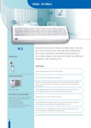
New generation 06T screw compressor<br />
The new generation of the Carrier 06T screw compressors<br />
benefits from Carrier’s long experience in the development of<br />
twin-rotor screw compressors. The compressor is equipped<br />
with bearings with oversized rollers, oil pressure lubricated<br />
for reliable and durable operation, even at maximum load.<br />
A variable control valve controlled by the oil pressure<br />
permits infinitely variable cooling capacity. This system<br />
allows optimal adjustment of the compressor cooling<br />
capacity and ensures exceptionally high stability of the<br />
chilled water leaving temperature.<br />
Among the other advantages: if a fault occurs e.g. if the<br />
condenser is fouled or at very high outside temperature, the<br />
compressor does not switch off, but continues operation with<br />
a reduced capacity (unloaded mode).<br />
The compressor is equipped with a separate oil separator that<br />
minimises the amount of oil in circulation in the refrigerant<br />
circuit and with its integrated silencer considerably reduces<br />
discharge gas pulsations for much quieter operation.<br />
3
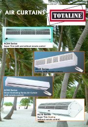
All aluminium micro-channel heat exchanger (MCHX)<br />
Already utilised in the automobile and aeronautical industries<br />
for many years, the MCHX used in the Aquaforce is entirely<br />
made of aluminium. This one-piece concept significantly<br />
increases its corrosion resistance by eliminating the galvanic<br />
currents that are created when two different metals (copper<br />
and aluminium) come into contact in a saline or corrosive<br />
atmosphere.<br />
From an energy efficiency point-of-view the MCHX heat<br />
exchanger is approximately 10% more efficient than a<br />
traditional coil and allows a 30% reduction in the amount of<br />
refrigerant used in the chiller. The low thickness of the<br />
MCHX reduces air pressure losses by 50% and makes it less<br />
susceptible to fouling by sand than a traditional coil.<br />
Cleaning of the MCHX heat exchanger is very fast using a<br />
high-pressure washer.<br />
Pro-Dialog operator interface with touch-screen<br />
The Aquaforce operator interface is very user-friendly. It is a<br />
large-format touch-screen, and the information is easily<br />
accessible: clear text in the selected language allows<br />
consultation of all operating parameters. Up to eight screens<br />
can be personalised.<br />
4
Options and accessories<br />
Options No. Description Advantages Use<br />
Corrosion protection, 2B Factory application of Blygold Polual treatment Improved corrosion resistance, recommended <strong>30XA</strong> <strong>252</strong>-<strong>1702</strong><br />
traditional coils on the copper/aluminium coils for industrial, rural and severe marine environments<br />
Corrosion protection, 3A Fins made of pre-treated aluminium Improved corrosion resistance, recommended for <strong>30XA</strong> <strong>252</strong>-<strong>1702</strong><br />
traditional coils (polyurethane and epoxy) moderate marine and urban environments<br />
Grilles 23 Metallic grilles on all four unit faces Improved aesthetics <strong>30XA</strong> <strong>252</strong>-<strong>1702</strong><br />
Evaporator frost protection 41A Resistance heater on the evaporator Evaporator frost protection down to -20°C <strong>30XA</strong> <strong>252</strong>-<strong>1702</strong><br />
outside temperature<br />
Evaporator and hydronic 41B Resistance heater on the evaporator and Evaporator and hydronic module frost <strong>30XA</strong> <strong>252</strong>-502<br />
module frost protection the hydronic module protection down to -20°C outside temperature<br />
Suction valve 92 Shut-off valves on the compressor suction piping Simplified maintenance <strong>30XA</strong> <strong>252</strong>-702<br />
Three-pass evaporator 100A Evaporator with three passes water-side Increased water inlet and outlet pressure losses <strong>30XA</strong> <strong>252</strong>-602<br />
on opposite sides<br />
One-pass evaporator 100C Evaporator with one pass water-side Reduced water inlet and outlet pressure <strong>30XA</strong> <strong>252</strong>-1002<br />
losses on opposite sides<br />
Reversed water connections 107 Evaporator with reversed water inlet/outlet Simplification of the water piping <strong>30XA</strong> <strong>252</strong>-<strong>1702</strong><br />
High-pressure single-pump 116B See hydronic module chapter Easy and fast installation <strong>30XA</strong> <strong>252</strong>-502<br />
hydronic module<br />
High-pressure dual-pump 116C See hydronic module chapter Easy and fast installation, operating safety <strong>30XA</strong> <strong>252</strong>-502<br />
hydronic module<br />
Low-pressure single-pump 116F See hydronic module chapter Easy and fast installation <strong>30XA</strong> <strong>252</strong>-502<br />
hydronic module<br />
Low-pressure dual-pump 116G See hydronic module chapter Easy and fast installation, operating safety <strong>30XA</strong> <strong>252</strong>-502<br />
hydronic module<br />
JBus gateway 148B Two-directional communications board, Easy connection by communication bus <strong>30XA</strong> <strong>252</strong>-<strong>1702</strong><br />
complies with JBus protocol<br />
to a building management system<br />
BacNet gateway 148C Two-directional communications board, Easy connection by communication bus <strong>30XA</strong> <strong>252</strong>-<strong>1702</strong><br />
complies with BacNet protocol<br />
to a building management system<br />
LON gateway 148D Two-directional communications board, Easy connection by communication bus <strong>30XA</strong> <strong>252</strong>-<strong>1702</strong><br />
complies with LON protocol<br />
to a building management system<br />
Energy Management 156 See chapter “Energy Management Module” Easy connection by wired connection <strong>30XA</strong> <strong>252</strong>-<strong>1702</strong><br />
Module EMM<br />
to a building management system<br />
Unit without enclosure 253 Compressors not equipped with acoustic enclosure More economical <strong>30XA</strong> <strong>252</strong>-<strong>1702</strong><br />
Traditional coils (Cu/Al) 255 Coils made of copper tubes with aluminium fins Recommended for the Middle East, sand storms. <strong>30XA</strong> <strong>252</strong>-<strong>1702</strong><br />
without slots without slots Possibility to add specialised condenser treatment.<br />
Accessories Description Advantages Use<br />
CCN JBus gateway See option 148B See option 148B See option<br />
148B<br />
CCN BacNet gateway See option 148C See option 148C See option<br />
148C<br />
CCN LON Talk gateway See option 148D See option 148D See option<br />
148D<br />
Connection sleeve Piping to be welded with Victaulic connection Ease-of-installation <strong>30XA</strong> <strong>252</strong>-<strong>1702</strong><br />
Energy Management Module EMM See controls manual Easy connection by wired connection to<br />
a building management system <strong>30XA</strong> <strong>252</strong>-<strong>1702</strong><br />
Lead-lag kit Supplementary water outlet temperature sensor kit, Optimised operation of two chillers connected <strong>30XA</strong> <strong>252</strong>-1502<br />
field-installed, allows master/slave operation of two in parallel with operating time balancing.<br />
chillers connected in parallel<br />
5
Hydronic module (option)<br />
12<br />
Typical hydronic circuit diagram<br />
Legend<br />
Components of unit and hydronic module<br />
1 Victaulic screen filter<br />
2 Expansion tank<br />
3 Safety valve<br />
4 Available pressure pump<br />
5 Pressure tap valve (see Installation Manual)<br />
6 Pressure gauge to measure the component pressure loss (see Installation Manual)<br />
7 System vent valve, pressure gauge<br />
8 Drain valve<br />
9 Water flow control valve<br />
10 Evaporator<br />
11 Evaporator defrost heater (option)<br />
12 Hydronic module defrost heater<br />
13 Air vent (evaporator)<br />
14 Water purge (evaporator)<br />
15 Expansion compensator (flexible connections)<br />
16 Flow switch<br />
17 Water temperature sensor<br />
System components<br />
18 Air vent<br />
19 Flexible connection<br />
20 Shut-down valves<br />
21 Charge valve<br />
--- Hydronic module (option)<br />
6
Physical data<br />
Unit with MCHX heat exchanger (standard)<br />
<strong>30XA</strong> high-ambient temperature version<br />
<strong>252</strong> 302 352 402 452 502 602 702 752 802 852 902 1002 1102 1202 1302 1352 1402 1502 <strong>1702</strong><br />
Nominal cooling capacity*<br />
Standard unit kW 274 300 326 393 451 508 616 677 726 792 837 899 999 1146 1245 1352 1440 1466 1521 1673<br />
Tons 78 85 93 112 128 144 175 192 206 225 238 256 284 326 354 384 409 417 432 476<br />
Cooling capacity**<br />
Standard unit kW 249 271 292 361 413 465 565 620 667 727 768 825 916 1052 1144 1240 1318 1346 1395 1536<br />
Tons 71 77 83 103 117 132 161 176 190 207 218 235 261 299 325 353 375 383 397 437<br />
Operating weight***<br />
Standard unit kg 3840 3880 3920 4780 4850 5330 6260 6410 6710 7010 7560 7860 8440 10440 10880 11260 11620 4250/ 4250/ 7560/<br />
8380 8530 7560<br />
Refrigerant<br />
R134a<br />
Standard unit<br />
Circuit A kg 36 37 37 53 55 62 62 62 70 70 77 70 80 69 85 87 87 100 92 77<br />
Circuit B kg 38 38 39 37 39 39 62 66 62 57 66 75 84 66 66 68 80 85 95 66<br />
Circuit C kg - - - - - - - - - - - - - 100 100 100 96 100 100 77<br />
Circuit D kg - - - - - - - - - - - - - - - - - - - 66<br />
Compressors<br />
06T semi-hermetic screw compressors, 50 r/s<br />
Circuit A 1 1 1 1 1 1 1 1 1 1 1 1 1 1 1 1 1 1 1 1<br />
Circuit B 1 1 1 1 1 1 1 1 1 1 1 1 1 1 1 1 1 1 1 1<br />
Circuit C - - - - - - - - - - - - - 1 1 1 1 1 1 1<br />
Circuit D - - - - - - - - - - - - - - - - - - - 1<br />
Minimum capacity % 15 15 15 15 15 15 15 15 15 15 15 15 15 10 10 10 10 10 10 8<br />
Control<br />
PRO-DIALOG, electronic expansion valve (EXV)<br />
Condensers<br />
Aluminium micro-channel heat exchanger<br />
Fans<br />
Axial Flying Bird 4 with rotating shroud<br />
Quantity, standard unit 6 6 6 8 8 9 11 12 12 12 14 14 16 19 20 20 20 24 24 28<br />
Standard total air flow l/s 27083 27083 27083 36111 36111 40625 49653 54167 54167 54167 63194 63194 72222 85764 90278 90278 90278 108333 108333 126389<br />
Standard speed r/s 15.7 15.7 15.7 15.7 15.7 15.7 15.7 15.7 15.7 15.7 15.7 15.7 15.7 15.7 15.7 15.7 15.7 15.7 15.7 15.7<br />
Evaporator<br />
Flooded multi-pipe type<br />
Water content l 58 61 61 66 70 77 79 94 98 119 119 130 140 168 182 203 224 230 240 240<br />
Maximum pressure**** kPa 1000 1000 1000 1000 1000 1000 1000 1000 1000 1000 1000 1000 1000 1000 1000 1000 1000 1000 1000 1000<br />
Water connections Victaulic<br />
Without hydronic module, inlet/outlet<br />
Diameter ‡ in 5 5 5 5 5 5 5 6 6 6 6 6 8 6 6 6 6/8 6/8 6/8 6<br />
Outside diameter ‡ mm 141.3 141.3 141.3 141.3 141.3 141.3 141.3 168.3 168.3 168.3 168.3 168.3 219.1 168.3 168.3 168.3 168.3/ 168.3/ 168.3/ 168.3<br />
219.3 219.3 219.3<br />
With hydronic module (option), inlet/outlet<br />
Diameter in 4 4 4 5 5 5 - - - - - - - - - - - - - -<br />
Outside diameter mm 114.3 114.3 114.3 139.7 139.7 139.7 - - - - - - - - - - - - - -<br />
Expansion tank<br />
volume l 50 50 50 50 50 80 - - - - - - - - - - - - - -<br />
Max. water-side operating pressure with hydronic module<br />
kPa 400 400 400 400 400 400 - - - - - - - - - - - - - -<br />
Legend:<br />
* Nominal conditions: evaporator entering/leaving water temperature = 12°C/7°C. Outdoor air temperature = 35°C, evaporator fouling factor = 0.000018 m 2 K/W<br />
** Operating conditions: evaporator entering/leaving water temperature = 12.7°C/7.2°C (45°F/55°F). Outdoor air temperature = 46.1°C (115°F)<br />
*** Weights are guidelines only. The refrigerant charge is also given on the unit nameplate. Weight and diameters of connection modules 1 and 2 for sizes 1402 to <strong>1702</strong>.<br />
**** Max. water-side operating pressure without hydronic module<br />
‡ Weight and diameters of connection modules 1 and 2 for sizes 1402 to <strong>1702</strong><br />
Note:<br />
Unit sizes <strong>30XA</strong> 1402 to <strong>1702</strong> are supplied in two field-assembled modules.<br />
Contact your Carrier representative to obtain the performances<br />
7
Physical data<br />
Unit with Cu/Al heat exchanger (option 255)<br />
<strong>30XA</strong> high-ambient temperature version<br />
<strong>252</strong> 302 352 402 452 502 602 702 752 802 852 902 1002 1102 1202 1302 1352 1402 1502 <strong>1702</strong><br />
Nominal cooling capacity*<br />
Standard unit kW 272 297 325 388 449 501 616 671 724 787 829 893 980 1134 1237 1344 1439 1448 1507 1656<br />
Tons 77 84 92 110 128 142 175 191 206 224 236 254 279 322 352 382 409 412 428 471<br />
Cooling capacity**<br />
Standard unit kW 246 267 291 355 410 457 564 613 665 719 757 818 895 1039 1135 1212 1244 1328 1380 1518<br />
Tons 70 76 83 101 117 130 160 174 189 204 215 233 254 295 323 345 354 378 392 432<br />
Operating weight***<br />
Standard unit kg 4160 4190 4710 5190 5260 5830 6870 7030 7820 8140 8260 9010 9260 11470 11890 12250 12640 9180 9340 8270<br />
4650 4650 8270<br />
Refrigerant<br />
R134a<br />
Standard unit<br />
Circuit A kg 60 64 70 85 85 102 102 100 129 112 130 129 140 102 112 112 112 140 140 130<br />
Circuit B kg 64 64 56 56 56 56 88 95 88 95 95 103 129 92 92 92 98 103 129 95<br />
Circuit C kg - - - - - - - - - - - - - 130 130 130 117 130 130 130<br />
Circuit D kg - - - - - - - - - - - - - - - - - - - 95<br />
Compressors<br />
06T semi-hermetic screw compressors, 50 r/s<br />
Circuit A 1 1 1 1 1 1 1 1 1 1 1 1 1 1 1 1 1 1 1 1<br />
Circuit B 1 1 1 1 1 1 1 1 1 1 1 1 1 1 1 1 1 1 1 1<br />
Circuit C - - - - - - - - - - - - - - 1 1 1 1 1 1 1<br />
Circuit D - - - - - - - - - - - - - - - - - - - 1<br />
Minimum capacity % 15 15 15 15 15 15 15 15 15 15 15 15 15 10 10 10 10 10 10 8<br />
Control<br />
PRO-DIALOG, electronic expansion valve (EXV)<br />
Condensers<br />
Copper/aluminium heat exchanger<br />
Fans<br />
Axial Flying Bird 4 with rotating shroud<br />
Quantity 6 6 7 8 8 9 11 12 13 13 14 15 16 19 20 20 20 24 24 28<br />
Standard total air flow l/s 27083 27083 27083 36111 36111 40625 49653 54167 54167 54167 63194 63194 72222 85764 90278 90278 90278 108333 108333 126389<br />
Standard speed r/s 15.7 15.7 15.7 15.7 15.7 15.7 15.7 15.7 15.7 15.7 15.7 15.7 15.7 15.7 15.7 15.7 15.7 15.7 15.7 15.7<br />
Evaporator<br />
Flooded multi-pipe type<br />
Water content l 58 61 61 66 70 77 79 94 98 119 119 130 140 168 182 203 224 230 240 240<br />
Maximum pressure**** kPa 1000 1000 1000 1000 1000 1000 1000 1000 1000 1000 1000 1000 1000 1000 1000 1000 1000 1000 1000 1000<br />
Water connections Victaulic<br />
Without hydronic module, inlet/outlet<br />
Diameter in 5 5 5 5 5 5 5 6 6 6 6 6 8 6 6 6 6/8 6/8 6/8 6<br />
Outside diameter mm 141.3 141.3 141.3 141.3 141.3 141.3 141.3 168.3 168.3 168.3 168.3 168.3 219.1 168.3 168.3 168.3 168.3/ 168.3/ 168.3/ 168.3<br />
219.3 219.3 219.3<br />
With hydronic module (option), inlet/outlet<br />
Diameter in 4 4 4 5 5 5 - - - - - - - - - - - - - -<br />
Outside diameter mm 114.3 114.3 114.3 139.7 139.7 139.7 - - - - - - - - - - - - - -<br />
Expansion tank<br />
volume l 50 50 50 50 50 80 - - - - - - - - - - - - - -<br />
Max. water-side operating pressure with hydronic module<br />
kPa 400 400 400 400 400 400 - - - - - - - - - - - - - -<br />
Legend:<br />
* Nominal conditions: evaporator entering/leaving water temperature = 12°C/7°C. Outdoor air temperature = 35°C, evaporator fouling factor = 0.000018 m 2 K/W<br />
** Operating conditions: evaporator entering/leaving water temperature = 12.7°C/7.2°C (45°F/55°F). Outdoor air temperature = 46.1°C (115°F)<br />
*** Weights are guidelines only. The refrigerant charge is also given on the unit nameplate.<br />
**** Max. water-side operating pressure without hydronic module<br />
Note:<br />
Unit sizes <strong>30XA</strong> 1402 to <strong>1702</strong> are supplied in two field-assembled modules.<br />
Contact your Carrier representative to obtain the performances<br />
8
Electrical data<br />
Unit with MCHX heat exchanger (standard)<br />
<strong>30XA</strong> high-ambient temperature version*<br />
<strong>252</strong> 302 352 402 452 502 602 702 752 802 852 902 1002 1102 1202 1302 1352 1402 1502 <strong>1702</strong><br />
Power circuit<br />
Nominal power<br />
supply V-ph-Hz 400-3-50<br />
Voltage range V 360-440<br />
Maximum supply cable section<br />
Circuits A + B mm 2 2x240 2x240 2x240 2x240 2x240 2x240 4x240 4x240 4x240 4x240 4x240 6x240 6x240 4x240 4x240 4x240 6x240 6x240 6x240 4x240<br />
Circuits C + D mm 2 - - - - - - - - - - - - - 2x240 2x240 2x240 2x240 2x240 2x240 4x240<br />
Short circuit holding current (TN system)**<br />
Circuits A + B kA 38 38 38 38 38 38 50 50 50 50 50 50 50 50 50 50 50 50 50 50<br />
Circuits C + D kA - - - - - - - - - - - - - 50 50 50 50 50 50 50<br />
Maximum start-up current***<br />
Circuits A + B A 262 262 283 400 507 507 579 608 778 803 807 892 945 579 778 803 889 892 945 807<br />
Circuits C + D A - - - - - - - - - - - - - 587 587 587 587 587 587 807<br />
Nominal start-up current****<br />
Circuits A + B A 244 244 261 377 479 479 536 560 735 755 759 842 862 536 735 755 839 842 862 759<br />
Circuits C + D A - - - - - - - - - - - - - 587 587 587 587 587 587 759<br />
Cosine Phi (maximum)† 0.88 0.87 0.87 0.88 0.88 0.88 0.88 0.88 0.86 0.86 0.86 0.85 0.85 0.88 0.86 0.87 0.85 0.85 0.85 0.86<br />
Cosine Phi (nominal)‡ 0.84 0.84 0.83 0.83 0.85 0.85 0.86 0.86 0.84 0.84 0.84 0.82 0.82 0.84 0.83 0.83 0.83 0.82 0.82 0.84<br />
Maximum power input††<br />
Circuits A + B kW 126 136 147 172 192 212 257 278 304 323 356 372 435 257 304 353 400 405 435 356<br />
Circuits C + D kW - - - - - - - - - - - - - 217 217 217 216 217 217 356<br />
Nominal unit current draw‡<br />
Circuits A+B A 149 165 182 210 239 262 320 343 404 423 446 511 549 320 404 439 523 534 549 446<br />
Circuits C+D A - - - - - - - - - - - - - 275 275 275 271 275 275 446<br />
Maximum unit current draw (Un) ††<br />
Circuits A + B A 208 226 243 284 316 350 423 457 512 542 596 635 734 423 512 588 678 688 734 596<br />
Circuits C + D A - - - - - - - - - - - - - 367 367 367 364 367 367 596<br />
Maximum unit current draw (Un – 10%) †<br />
Circuits A + B A 219 243 262 305 340 376 455 491 551 583 640 683 790 455 551 633 729 740 790 640<br />
Circuits C + D A - - - - - - - - - - - - - 395 395 395 391 395 395 640<br />
Legend<br />
* Motor and fan electrical data if the unit operates at Eurovent conditions (motor ambient temperature 50°C); 3,6 A, start-up current: 20 A, power input: 1.65 kW<br />
** kA eff: efficiency value: rms for English version<br />
*** Instantaneous start-up current (operating current of the smallest compressor + fan current + locked rotor current in star connection of the largest compressor). Values obtained at<br />
operation with maximum unit power input.<br />
**** Instantaneous start-up current (operating current of the smallest compressor + fan current + locked rotor current in star connection of the largest compressor). Values obtained at<br />
standard Eurovent unit operating conditions: air 35°C, water 12/7°C<br />
† Values obtained at operation with maximum unit power input.<br />
‡ Values obtained at standard Eurovent unit operating conditions: air 35°C, water 12/7°C<br />
†† Values obtained at operation with maximum unit power input. Values given on the unit name plate<br />
Electrical data<br />
Unit with copper/aluminium heat exchanger (option 255)<br />
<strong>30XA</strong> high-ambient temperature version*<br />
<strong>252</strong> 302 352 402 452 502 602 702 752 802 852 902 1002 1102 1202 1302 1352 1402 1502 <strong>1702</strong><br />
Maximum start-up current**<br />
Circuits A + B A 272 272 295 400 507 507 579 608 778 807 807 892 945 579 778 803 889 892 945 807<br />
Circuits C + D A - - - - - - - - - - - - - 587 587 587 587 587 587 807<br />
Nominal start-up current***<br />
Circuits A + B A 244 244 261 377 479 479 536 560 735 759 759 842 862 536 735 755 839 842 862 759<br />
Circuits C + D A - - - - - - - - - - - - - 587 587 587 587 587 587 759<br />
Cosine Phi (maximum)**** 0.88 0.87 0.87 0.88 0.88 0.88 0.88 0.88 0.86 0.86 0.86 0.84 0.85 0.88 0.86 0.87 0.85 0.85 0.85 0.86<br />
Cosine Phi (nominal)† 0.84 0.84 0.83 0.83 0.85 0.85 0.86 0.86 0.83 0.84 0.84 0.82 0.82 0.84 0.83 0.83 0.83 0.82 0.82 0.84<br />
Maximum power input††<br />
Circuits A + B kW 126 136 148 172 192 212 257 278 306 325 356 373 435 257 304 353 400 405 435 356<br />
Circuits C + D kW - - - - - - - - - - - - - 217 217 217 216 217 217 356<br />
Nominal unit current draw†<br />
Circuits A + B A 149 165 185 210 239 262 320 343 407 427 446 514 549 320 404 439 523 534 549 446<br />
Circuits C + D A - - - - - - - - - - - - - 275 275 275 275 275 275 446<br />
Maximum unit current draw (Un)††<br />
Circuits A + B A 208 226 247 284 316 350 423 457 516 546 596 639 734 423 512 588 678 688 734 596<br />
Circuits C + D A - - - - - - - - - - - - - 367 367 367 364 367 367 596<br />
Maximum unit current draw (Un – 10%)****<br />
Circuits A + B A 219 243 266 305 340 376 455 491 555 587 640 687 790 455 551 633 729 740 790 640<br />
Circuits C + D A - - - - - - - - - - - - - 395 395 395 391 395 395 640<br />
Legend<br />
* Motor and fan electrical data if the unit operates at Eurovent conditions (motor ambient temperature 50°C); 3,6 A, start-up current: 20 A, power input: 1.65 kW<br />
** Instantaneous start-up current (operating current of the smallest compressor + fan current + locked rotor current in star connection of the largest compressor). Values obtained at<br />
operation with maximum unit power input.<br />
*** Instantaneous start-up current (operating current of the smallest compressor + fan current + locked rotor current in star connection of the largest compressor). Values obtained at<br />
standard Eurovent unit operating conditions: air 35°C, water 12/7°C<br />
**** Values obtained at operation with maximum unit power input.<br />
† Values obtained at standard Eurovent unit operating conditions: air 35°C, water 12/7°C<br />
†† Values obtained at operation with maximum unit power input. Values given on the unit name plate<br />
9
Electrical data notes<br />
• <strong>30XA</strong> <strong>252</strong>-1002 units have a single power connection point located<br />
immediately upstream of the two main disconnect switches.<br />
• <strong>30XA</strong> 1102-<strong>1702</strong> units have two power connection points located upstream<br />
of the main disconnect switches.<br />
• The control box includes:<br />
- One main disconnect switch per circuit<br />
- Starter and motor protection devices for each compressor, the fans and<br />
the pump<br />
- Control devices<br />
• Field connections:<br />
All connections to the system and the electrical installations must be in full<br />
accordance with all applicable local codes.<br />
• The Carrier <strong>30XA</strong> units are designed and built to ensure conformance with<br />
these codes. The recommendations of European standard EN 60 204-1<br />
(corresponds to IEC 60204-1) (machine safety - electrical machine<br />
components - part 1: general regulations) are specifically taken into<br />
account, when designing the electrical equipment.<br />
Notes:<br />
• Generally the recommendations of IEC 60364 are accepted as compliance<br />
with the requirements of the installation directives. Conformance with EN<br />
60204 is the best means of ensuring compliance with the Machines<br />
Directive § 1.5.1.<br />
• Annex B of EN 60204-1 describes the electrical characteristics used for the<br />
operation of the machines.<br />
1. The operating environment for the <strong>30XA</strong> units is specified below:<br />
• Environment* - Environment as classified in EN 60721 (corresponds to<br />
IEC 60721) :<br />
- outdoor installation*<br />
- ambient temperature range: minimum temperature -20°C to +55°C,<br />
class 4K4H*<br />
- altitude: lower than or equal to 2000 m<br />
- presence of hard solids, class 4S2 (no significant dust present)<br />
- presence of corrosive and polluting substances, class 4C2 (negligible)<br />
2. Power supply frequency variation: ± 2 Hz.<br />
3. The neutral (N) line must not be connected directly to the unit (if necessary<br />
use a transformer).<br />
4. Overcurrent protection of the power supply conductors is not provided with<br />
the unit.<br />
5. The factory-installed disconnect switch(es)/circuit breaker(s) is (are) of a type<br />
suitable for power interruption in accordance with EN 60947-3 (corresponds<br />
to IEC 60947-3).<br />
6. The units are designed for simplified connection on TN(s) networks<br />
(IEC 60364). For IT networks derived currents may interfere with network<br />
monitoring elements, and it is recommended to create an IT type divider for<br />
the system units that require this and/or a TN type divider for Carrier units.<br />
Please consult the appropriate local organisations to define the monitoring<br />
and protection elements and carry out the electrical installation.<br />
NOTE: If particular aspects of an actual installation do not conform to the<br />
conditions described above, or if there are other conditions which should<br />
be considered, always contact your local Carrier representative.<br />
* The required protection level for this class is IP43B (according to reference<br />
document IEC 60529). All <strong>30XA</strong> units are protected to IP54 and fulfil this<br />
protection condition.<br />
10
Sound levels<br />
<strong>30XA</strong> high-ambient temperature version<br />
<strong>252</strong> 302 352 402 452 502 602 702 752 802 852 902 1002 1102 1202 1302 1352 1402 1502 <strong>1702</strong><br />
Sound power level* dB(A) 94 94 94 95 95 95 96 96 98 98 98 99 98 99 100 99 100 101 100 101<br />
Sound pressure level at 10 m** dB(A) 62 62 62 63 63 63 63 63 65 65 65 66 65 66 67 66 67 68 67 67<br />
* 10 -12 W - In accordance with ISO 9614-1 and certified by Eurovent<br />
** Average sound pressure level, unit in a free field on a reflective surface<br />
Part load performances<br />
With the rapid increase in energy costs and the care about<br />
environmental impacts of electricity production, power<br />
consumption of air conditioning equipment has become an<br />
important topic. The energy efficiency of a liquid chiller at<br />
full load is rarely representative of the actual performance of<br />
the units, as on average a chiller works less than 5% of the<br />
time at full load.<br />
IPLV (in accordance with ARI 550/590-98)<br />
The IPLV (integrated part load value) allows evaluation of<br />
the average energy efficiency based on four operating<br />
conditions defined by the ARI (American Refrigeration<br />
Institute). The IPLV is the average weighted value of the<br />
energy efficiency ratios (EER) at different operating<br />
conditions, weighted by the operating time.<br />
The heat load of a building depends on many factors, such<br />
as the outside air temperature, the exposure to the sun and<br />
its occupation.<br />
Consequently it is preferable to use the average energy<br />
efficiency, calculated at several operating points that are<br />
representative for the unit utilisation.<br />
ESEER (in accordance with EUROVENT)<br />
The ESEER (European seasonal energy efficiency ratio)<br />
permits evaluation of the average energy efficiency at part<br />
load, based on four operating conditions defined by Eurovent.<br />
The ESEER is the average value of energy efficiency ratios<br />
(EER) at different operating conditions, weighted by the<br />
operating time.<br />
IPLV (Integrated Part Load Value)<br />
Load Air temperature Energy Operating<br />
(%) (°C) efficiency time, %<br />
100 35 EER 1 1<br />
75 26.7 EER 2 42<br />
50 18.3 EER 3 45<br />
25 12.8 EER 4 12<br />
IPLV = EER 1 x 1% + EER 2 x 42% + EER 3 x 45% + EER 4 x 12%<br />
ESEER (European seasonal energy efficiency ratio)<br />
Load Air temperature Energy Operating<br />
(%) (°C) efficiency time, %<br />
100 35 EER 1 3<br />
75 30 EER 2 33<br />
50 25 EER 3 41<br />
25 20 EER 4 23<br />
ESEER = EER 1 x 3% + EER 2 x 33% + EER 3 x 41% + EER 4 x 23%<br />
Part load performances<br />
<strong>30XA</strong> <strong>252</strong> 302 352 402 452 502 602 702 752 802 852 902 1002 1102 1202 1302 1352 1402 1502 <strong>1702</strong><br />
High ambient temperature version<br />
IPLV kW/kW 4.31 4.48 4.58 4.45 4.67 4.69 4.48 4.64 4.61 4.57 4.55 4.32 4.40 4.66 4.54 4.66 4.62 4.56 4.57 4.44<br />
ESEER kW/kW 3.93 4.03 4.08 4.05 4.19 4.19 4.03 4.18 3.99 4.10 4.14 3.91 3.95 4.24 4.10 4.23 4.15 4.13 4.16 4.04<br />
11
Operating limits<br />
Evaporator water temperature<br />
°C Minimum Maximum<br />
Water entering temperature at start-up - 45<br />
Water entering temperature during operation 6.8 21<br />
Water leaving temperature during operation 3.3 15<br />
Note: If the leaving water temperature is below 4°C, a glycol/water solution or the frost<br />
protection option must be used.<br />
Condenser air temperature<br />
°C Minimum Maximum<br />
Storage -20 68<br />
Operation -10 55*<br />
* Part-load operation<br />
Note: If the air temperature is below 0°C, a glycol/water solution or the frost protection<br />
option must be used.<br />
Evaporator water flow rate, l/s<br />
<strong>30XA</strong> Minimum Maximum*<br />
<strong>252</strong> 3.6 37.5<br />
302 4 40.5<br />
352 4.3 40.5<br />
402 5.3 34.1<br />
452 6 36.9<br />
502 6.7 42<br />
602 8.1 45<br />
702 8.9 56.1<br />
752 9.6 59.1<br />
802 10.4 67.1<br />
852 11 67.1<br />
902 11.8 73.9<br />
1002 13.1 83.9<br />
1102 15.1 87.8<br />
1202 16.4 92.9<br />
1302 17.5 96.1<br />
1352 18.8 107.4<br />
1402 19.3 107.4<br />
1502 19.9 109.4<br />
<strong>1702</strong> 22 107.4<br />
* The maximum water flow rate corresponds to a pressure drop of 100 kPa.<br />
Operating range<br />
Legend<br />
Entering air temperature, °C<br />
Part load<br />
Operating range, standard unit.<br />
Below 0°C air temperature the unit must either be equipped with the<br />
evaporator frost protection option (41A or 41B), or the water loop must be<br />
protected against frost by using a frost protection solution (by the installer).<br />
Evaporator leaving water temperature, °C<br />
12
Dimensions/clearances<br />
<strong>30XA</strong> <strong>252</strong>-352 - MCHX heat exchanger (standard)<br />
<strong>30XA</strong> <strong>252</strong>-302 - Cu/Al heat exchanger (option 255)<br />
Legend:<br />
All dimensions are given in mm.<br />
Required clearances for maintenance<br />
and air flow<br />
Recommended space for evaporator<br />
tube removal<br />
Water inlet<br />
Water outlet<br />
Air outlet – do not obstruct<br />
<strong>30XA</strong> 402-452 - MCHX heat exchanger (standard)<br />
<strong>30XA</strong> 352-452 - Cu/Al heat exchanger (option 255)<br />
Power supply connection<br />
Control circuit connection<br />
NOTE:<br />
Drawings are not contractually binding.<br />
Before designing an installation, consult<br />
the certified dimensional drawings,<br />
available on request.<br />
13
Dimensions/clearances<br />
<strong>30XA</strong> 502 - MCHX heat exchanger (standard)<br />
<strong>30XA</strong> 502 - Cu/Al heat exchanger (option 255)<br />
<strong>30XA</strong> 602-802 - MCHX heat exchanger (standard)<br />
<strong>30XA</strong> 602-702 - Cu/Al heat exchanger (option 255)<br />
Legend:<br />
All dimensions are given in mm.<br />
Required clearances for maintenance<br />
and air flow<br />
Recommended space for evaporator<br />
tube removal<br />
Water inlet<br />
Water outlet<br />
Air outlet – do not obstruct<br />
NOTE:<br />
Drawings are not contractually binding. Before designing an installation, consult the certified dimensional drawings, available on request.<br />
Power supply connection<br />
Control circuit connection<br />
14
Dimensions/clearances<br />
<strong>30XA</strong> 852-902 - MCHX heat exchanger (standard)<br />
<strong>30XA</strong> 752-852 - Cu/Al heat exchanger (option 255)<br />
Legend:<br />
All dimensions are given in mm.<br />
Required clearances for maintenance and air flow<br />
Recommended space for evaporator tube<br />
removal<br />
Water inlet<br />
Water outlet<br />
Air outlet – do not obstruct<br />
Power supply connection<br />
Control circuit connection<br />
NOTE:<br />
Drawings are not contractually binding. Before designing an installation, consult the certified dimensional drawings, available on request.<br />
15
Dimensions/clearances<br />
<strong>30XA</strong> 1002 - MCHX heat exchanger (standard)<br />
<strong>30XA</strong> 902-1002 - Cu/Al heat exchanger (option 255)<br />
Legend:<br />
All dimensions are given in mm.<br />
Required clearances for maintenance and air flow<br />
Recommended space for evaporator tube<br />
removal<br />
Water inlet<br />
Water outlet<br />
Air outlet – do not obstruct<br />
Power supply connection<br />
Control circuit connection<br />
NOTE:<br />
Drawings are not contractually binding. Before designing an installation, consult the certified<br />
dimensional drawings, available on request.<br />
16
Dimensions/clearances<br />
<strong>30XA</strong> 1102-1352 - MCHX heat exchanger (standard)<br />
<strong>30XA</strong> 1102-1352 - Cu/Al heat exchanger (option 255)<br />
Legend:<br />
All dimensions are given in mm.<br />
Required clearances for maintenance and air flow<br />
Recommended space for evaporator tube<br />
removal<br />
Water inlet<br />
Water outlet<br />
Air outlet – do not obstruct<br />
Power supply connection<br />
Control circuit connection<br />
NOTE:<br />
Drawings are not contractually binding. Before designing an installation, consult the certified dimensional<br />
drawings, available on request.<br />
17
Dimensions/clearances<br />
<strong>30XA</strong> 1402-1502, module 1/2 - MCHX heat exchanger (standard)<br />
<strong>30XA</strong> 1402-1502, module 1/2 - Cu/Al heat exchanger (option 255)<br />
Legend:<br />
All dimensions are given in mm.<br />
Required clearances for maintenance and air flow<br />
Recommended space for evaporator tube<br />
removal<br />
Water inlet<br />
Water outlet (to be connected to the water<br />
inlet of module 2)<br />
Air outlet – do not obstruct<br />
Power supply connection<br />
Control circuit connection<br />
Module 2<br />
NOTE:<br />
Drawings are not contractually binding. Before designing an installation, consult the certified dimensional drawings, available on request.<br />
18
Dimensions/clearances<br />
<strong>30XA</strong> 1402-1502, module 2/2 - MCHX heat exchanger (standard)<br />
<strong>30XA</strong> 1402-1502, module 2/2 - Cu/Al heat exchanger (option 255)<br />
Legend:<br />
All dimensions are given in mm.<br />
Required clearances for maintenance and air flow<br />
Recommended space for evaporator tube<br />
removal<br />
Water inlet (to be connected to the water outlet of<br />
module 1)<br />
Water outlet<br />
Air outlet – do not obstruct<br />
Power supply connection<br />
Control circuit connection<br />
Module 1<br />
NOTE:<br />
Drawings are not contractually binding. Before designing an installation, consult the certified dimensional drawings, available on request.<br />
Unit sizes 1402-1502 are supplied in two field-assembled modules (connection pipe completion to be done by the installer).<br />
19
Dimensions/clearances<br />
<strong>30XA</strong> <strong>1702</strong>, module 1/2 - MCHX heat exchanger (standard)<br />
<strong>30XA</strong> <strong>1702</strong>, module 1/2 - Cu/Al heat exchanger (option 255)<br />
Legend:<br />
All dimensions are given in mm.<br />
Required clearances for maintenance<br />
and air flow<br />
Recommended space for evaporator<br />
tube removal<br />
Water inlet<br />
Water outlet (to be connected to the<br />
water inlet of module 2)<br />
Air outlet – do not obstruct<br />
Power supply connection<br />
Control circuit connection<br />
Module 2<br />
NOTE:<br />
Drawings are not contractually binding. Before designing an installation, consult the certified dimensional drawings, available on request.<br />
Unit size <strong>1702</strong> is supplied in two field-assembled modules (connection pipe completion to be done by the installer).<br />
20
Dimensions/clearances<br />
<strong>30XA</strong> <strong>1702</strong>, module 2/2 - MCHX heat exchanger (standard)<br />
<strong>30XA</strong> <strong>1702</strong>, module 2/2 - Cu/Al heat exchanger (option 255)<br />
Module 1<br />
Legend:<br />
All dimensions are given in mm.<br />
Required clearances for maintenance<br />
and air flow<br />
Recommended space for evaporator<br />
tube removal<br />
Water inlet<br />
Water outlet (to be connected to the<br />
water inlet of module 2)<br />
Air outlet – do not obstruct<br />
Power supply connection<br />
Control circuit connection<br />
NOTE:<br />
Drawings are not contractually binding. Before designing an installation, consult the certified dimensional drawings, available on request.<br />
Unit size <strong>1702</strong> is supplied in two field-assembled modules (connection pipe completion to be done by the installer).<br />
21
Cooling capacities (SI)<br />
Unit with MCHX heat exchanger (standard)<br />
High ambient temperature unit - LWT = 5°C<br />
Air temperature, °C<br />
30 35 40 46 49 52<br />
CAP COMP UNIT COOL COOL CAP COMP UNIT COOL COOL CAP COMP UNIT COOL COOL CAP COMP UNIT COOL COOL CAP COMP UNIT COOL COOL CAP COMP UNIT COOL COOL<br />
<strong>30XA</strong> kW kW kW l/s kPa kW kW kW l/s kPa kW kW kW l/s kPa kW kW kW l/s kPa kW kW kW l/s kPa kW kW kW l/s kPa<br />
<strong>252</strong> 267 69 79 13 13 257 76 85 12 12 247 84 93 12 12 233 93 102 11 10 225 99 107 11 10 217 104 113 10 9<br />
302 294 77 86 14 14 282 84 93 13 13 269 93 102 13 12 253 104 112 12 10 244 110 118 12 10 235 116 124 11 9<br />
352 320 84 93 15 16 307 93 102 15 15 292 101 110 14 14 273 114 123 13 12 264 121 129 13 11 254 128 136 12 11<br />
402 382 96 108 18 31 369 105 117 18 30 355 115 127 17 28 338 128 140 16 25 328 135 147 16 24 318 143 154 15 23<br />
452 440 113 125 21 34 425 124 136 20 32 408 136 148 19 30 387 153 164 18 27 376 161 173 18 26 364 171 182 17 24<br />
502 496 124 138 24 34 479 136 150 23 31 459 149 163 22 29 435 166 180 21 26 422 176 190 20 25 407 186 200 19 23<br />
602 599 154 171 29 42 578 169 186 28 39 556 185 202 26 36 527 206 223 25 33 512 218 234 24 31 496 231 247 24 29<br />
702 660 163 182 31 34 637 178 197 30 32 612 195 214 29 29 581 218 237 28 27 564 230 249 27 25 546 244 262 26 24<br />
752 708 190 209 34 35 683 208 226 33 32 658 228 246 31 30 625 254 273 30 28 607 269 287 29 26 567 271 289 27 23<br />
802 773 202 223 37 33 746 222 242 36 31 717 243 263 34 28 681 271 291 32 26 662 287 307 32 25 612 285 305 29 21<br />
852 818 206 230 39 36 789 226 249 38 34 758 248 271 36 32 720 277 299 34 29 699 293 315 33 27 654 296 318 31 24<br />
902 878 232 256 42 34 847 254 278 40 32 815 279 302 39 30 774 312 334 37 27 752 330 352 36 26 677 317 340 32 21<br />
1002 976 249 278 46 34 942 272 301 45 32 905 299 327 43 30 859 334 362 41 27 835 354 381 40 26 773 353 380 37 22<br />
1102 1119 281 312 53 39 1080 307 338 51 36 1038 336 367 49 34 985 376 405 47 31 957 397 427 46 29 895 401 430 43 26<br />
1202 1216 314 347 58 40 1174 344 376 56 38 1129 376 409 54 35 1073 421 452 51 32 1043 445 476 50 30 956 438 468 46 26<br />
1302 1322 346 379 63 44 1275 379 412 61 41 1226 416 449 58 38 1163 466 498 55 35 1106 478 509 53 32 994 460 491 47 26<br />
1352 1411 380 411 67 41 1360 417 448 65 38 1306 457 488 62 35 1238 512 542 59 32 1124 494 524 54 27 901 424 453 43 18<br />
1402 1433 363 404 68 43 1383 397 437 66 40 1330 436 475 63 37 1263 487 526 60 34 1228 515 554 58 32 1067 477 514 51 25<br />
1502 1489 375 416 71 44 1436 411 451 68 41 1380 450 490 66 38 1309 504 543 62 35 1272 533 572 61 33 1087 487 525 52 24<br />
<strong>1702</strong> 1635 413 459 78 53 1578 452 498 75 50 1517 495 541 72 46 1440 554 598 69 42 1399 586 630 67 40 1<strong>252</strong> 565 608 60 32<br />
High ambient temperature unit - LWT = 6°C<br />
Air temperature, °C<br />
30 35 40 46 49 52<br />
CAP COMP UNIT COOL COOL CAP COMP UNIT COOL COOL CAP COMP UNIT COOL COOL CAP COMP UNIT COOL COOL CAP COMP UNIT COOL COOL CAP COMP UNIT COOL COOL<br />
<strong>30XA</strong> kW kW kW l/s kPa kW kW kW l/s kPa kW kW kW l/s kPa kW kW kW l/s kPa kW kW kW l/s kPa kW kW kW l/s kPa<br />
<strong>252</strong> 276 71 80 13 14 266 77 86 13 13 255 85 94 12 12 240 95 104 11 11 232 100 109 11 10 224 105 114 11 10<br />
302 303 78 87 14 14 291 86 95 14 13 278 94 103 13 12 261 105 114 12 11 <strong>252</strong> 111 120 12 10 243 118 126 12 10<br />
352 330 86 95 16 17 316 94 103 15 16 301 103 112 14 14 282 116 124 13 13 272 123 131 13 12 262 130 139 12 11<br />
402 395 97 109 19 33 381 106 118 18 31 367 116 128 17 29 349 130 142 17 26 339 137 149 16 25 329 145 156 16 24<br />
452 454 115 127 22 36 438 127 138 21 34 421 139 150 20 31 399 155 166 19 28 387 164 175 18 27 372 171 182 18 25<br />
502 511 126 140 24 35 493 138 152 23 33 473 151 165 23 31 448 169 183 21 28 435 179 193 21 26 412 186 199 20 24<br />
602 619 157 174 29 44 597 172 189 28 41 574 188 205 27 38 545 210 226 26 35 529 222 238 25 33 513 234 250 24 31<br />
702 681 165 185 32 36 657 181 200 31 33 632 198 217 30 31 599 221 240 29 28 581 234 253 28 27 563 248 266 27 25<br />
752 730 193 212 35 36 705 211 230 34 34 678 231 250 32 32 644 258 277 31 29 626 273 291 30 27 577 270 288 27 24<br />
802 797 206 226 38 34 769 225 245 37 32 739 247 267 35 30 702 276 295 33 27 682 291 311 33 26 623 285 304 30 22<br />
852 843 210 233 40 38 813 230 253 39 36 782 <strong>252</strong> 275 37 33 741 281 304 35 30 720 298 320 34 29 667 297 319 32 25<br />
902 905 236 260 43 36 873 259 282 42 33 839 283 306 40 31 797 316 339 38 28 775 335 357 37 27 681 313 335 32 21<br />
1002 1007 253 282 48 36 971 277 306 46 33 933 304 332 44 31 885 340 367 42 28 860 359 387 41 27 715 320 347 34 19<br />
1102 1153 285 316 55 41 1113 312 343 53 38 1070 342 372 51 35 1015 382 411 48 32 986 404 433 47 31 908 398 427 43 26<br />
1202 1254 319 352 60 42 1210 349 382 58 40 1164 383 415 55 37 1105 427 459 53 33 1074 452 483 51 32 962 431 462 46 26<br />
1302 1362 352 385 65 46 1314 386 419 63 43 1263 423 456 60 40 1198 473 505 57 36 1133 481 513 54 33 1012 460 491 48 27<br />
1352 1454 388 419 69 43 1401 425 455 67 40 1345 466 496 64 37 1274 521 551 61 34 1084 463 493 52 25 914 421 450 44 18<br />
1402 1478 370 410 70 45 1425 404 444 68 42 1370 443 482 65 39 1301 495 534 62 35 1264 524 562 60 34 1088 477 514 52 25<br />
1502 1534 382 422 73 46 1479 418 458 70 43 1421 458 498 68 40 1348 512 551 64 36 1309 542 580 62 34 1053 464 501 50 23<br />
<strong>1702</strong> 1684 420 466 80 56 1625 459 505 77 52 1562 503 549 74 49 1483 562 607 71 44 1440 595 639 69 42 1285 570 613 61 34<br />
Legend<br />
LWT Leaving water temperature<br />
CAP kW Cooling capacity<br />
COMP kW Compressor power input<br />
UNIT kW Unit power input (compressors, fans and control circuit)<br />
COOL l/s Evaporator water flow rate<br />
COOL kPa Evaporator pressure drop<br />
Application data:<br />
Standard units, refrigerant: R134a<br />
Evaporator temperature rise: 5 K<br />
Evaporator fluid: chilled water<br />
Fouling factor: 0.18 x 10 -4 (m 2 K)/W<br />
Performances in accordance with EN 14511.<br />
22
Cooling capacities (SI)<br />
Unit with MCHX heat exchanger (standard)<br />
High ambient temperature unit - LWT = 7.2°C<br />
Air temperature, °C<br />
30 35 40 46 49 52<br />
CAP COMP UNIT COOL COOL CAP COMP UNIT COOL COOL CAP COMP UNIT COOL COOL CAP COMP UNIT COOL COOL CAP COMP UNIT COOL COOL CAP COMP UNIT COOL COOL<br />
<strong>30XA</strong> kW kW kW l/s kPa kW kW kW l/s kPa kW kW kW l/s kPa kW kW kW l/s kPa kW kW kW l/s kPa kW kW kW l/s kPa<br />
<strong>252</strong> 286 72 81 14 15 276 79 88 13 14 264 86 95 13 13 249 96 105 12 12 241 101 110 11 11 233 107 115 11 10<br />
302 315 80 89 15 15 302 87 96 14 14 288 96 105 14 13 271 107 116 13 12 262 113 122 12 11 <strong>252</strong> 120 128 12 10<br />
352 343 88 97 16 18 328 96 105 16 17 312 105 114 15 15 292 118 127 14 13 282 125 134 13 13 264 127 135 13 11<br />
402 409 99 111 20 35 395 108 120 19 33 380 118 130 18 31 361 132 144 17 28 351 139 151 17 27 341 147 158 16 25<br />
452 470 118 130 22 38 454 129 141 22 36 436 141 153 21 33 413 158 169 20 30 401 167 178 19 29 373 166 177 18 25<br />
502 530 128 143 25 38 511 141 155 24 35 490 154 168 23 33 465 172 186 22 29 451 183 196 21 28 424 186 200 20 25<br />
602 642 160 177 31 47 620 175 192 30 44 596 192 208 28 41 565 214 230 27 37 549 226 242 26 35 524 234 250 25 32<br />
702 706 169 188 34 38 681 185 204 32 35 655 202 221 31 33 620 225 244 30 30 602 238 257 29 28 583 <strong>252</strong> 271 28 27<br />
752 757 197 216 36 39 730 215 234 35 36 702 236 254 33 34 667 263 281 32 31 648 278 296 31 29 530 239 257 25 20<br />
802 826 210 230 39 36 797 229 250 38 34 766 251 271 37 32 727 281 300 35 29 707 297 316 34 27 594 262 281 28 20<br />
852 874 214 238 42 40 842 234 258 40 38 810 257 280 39 35 768 287 309 37 32 745 303 325 36 30 628 274 296 30 22<br />
902 938 241 265 45 38 904 264 287 43 35 869 289 312 41 33 825 322 345 39 30 802 341 363 38 28 645 288 310 31 19<br />
1002 1043 259 287 50 38 1005 283 311 48 35 966 310 338 46 33 916 346 374 44 30 890 366 393 42 28 678 295 322 32 17<br />
1102 1196 292 323 57 43 1153 319 349 55 40 1109 349 379 53 38 1052 389 419 50 34 1022 411 441 49 32 857 367 396 41 23<br />
1202 1299 326 359 62 45 1254 357 389 60 42 1205 390 423 57 39 1144 436 467 55 35 1112 460 492 53 34 865 376 407 41 21<br />
1302 1412 360 393 67 49 1361 394 427 65 46 1308 432 464 62 43 1240 483 515 59 39 1123 462 494 54 32 964 429 460 46 24<br />
1352 1506 397 428 72 46 1450 434 465 69 42 1392 476 506 66 39 1318 532 562 63 36 1026 419 448 49 22 916 412 441 44 18<br />
1402 1532 378 418 73 48 1476 413 453 70 45 1419 452 491 68 41 1346 504 543 64 38 1300 529 567 62 35 1050 450 487 50 24<br />
1502 1590 391 431 76 49 1532 427 467 73 46 1471 467 507 70 42 1395 522 561 67 38 1348 549 587 64 36 1028 444 481 49 22<br />
<strong>1702</strong> 1746 429 475 83 60 1684 469 515 80 56 1619 513 559 77 52 1536 573 618 73 47 1491 607 651 71 44 1255 543 587 60 32<br />
High ambient temperature unit - LWT = 10°C<br />
Air temperature, °C<br />
30 35 40 46 49 52<br />
CAP COMP UNIT COOL COOL CAP COMP UNIT COOL COOL CAP COMP UNIT COOL COOL CAP COMP UNIT COOL COOL CAP COMP UNIT COOL COOL CAP COMP UNIT COOL COOL<br />
<strong>30XA</strong> kW kW kW l/s kPa kW kW kW l/s kPa kW kW kW l/s kPa kW kW kW l/s kPa kW kW kW l/s kPa kW kW kW l/s kPa<br />
<strong>252</strong> 312 75 84 15 17 300 82 91 14 16 287 90 99 14 15 271 100 109 13 13 262 105 114 13 12 253 111 119 12 12<br />
302 342 83 93 16 18 328 91 100 16 16 313 100 109 15 15 294 112 121 14 13 284 118 127 14 13 262 115 124 12 11<br />
352 372 92 101 18 21 356 101 110 17 19 338 110 119 16 17 317 124 133 15 15 306 131 140 15 14 270 120 128 13 11<br />
402 446 103 115 21 40 430 112 124 21 38 414 123 135 20 35 393 136 148 19 32 382 144 155 18 31 371 152 163 18 29<br />
452 510 124 136 24 44 492 135 147 23 41 472 148 160 23 38 448 165 177 21 34 435 175 186 21 33 378 156 167 18 25<br />
502 575 135 149 27 43 554 147 162 26 40 532 161 176 25 37 504 181 194 24 34 489 191 205 23 32 432 177 190 21 25<br />
602 698 168 185 33 54 674 183 200 32 50 648 200 217 31 47 614 223 240 29 42 597 236 <strong>252</strong> 28 40 541 227 243 26 34<br />
702 767 177 197 37 43 739 193 213 35 41 710 211 231 34 38 673 236 255 32 34 653 249 268 31 32 595 240 259 28 27<br />
752 823 207 226 39 44 793 226 245 38 41 762 247 265 36 39 723 275 293 35 35 686 281 299 33 32 563 238 256 27 22<br />
802 898 220 241 43 42 865 240 261 41 39 831 263 283 40 36 789 293 313 38 33 750 300 320 36 30 652 273 292 31 23<br />
852 948 225 249 45 46 914 246 269 44 43 878 269 292 42 40 831 300 323 40 36 794 310 332 38 33 668 274 296 32 24<br />
902 1019 254 277 49 43 981 277 300 47 40 942 303 326 45 38 893 337 360 43 34 834 337 360 40 30 656 272 294 31 19<br />
1002 1132 272 301 54 43 1091 297 326 52 40 1047 325 353 50 38 993 363 390 47 34 950 376 403 45 31 748 307 334 36 20<br />
1102 1297 306 337 62 50 1250 335 365 60 46 1202 365 396 57 43 1140 407 437 54 39 1093 423 452 52 36 907 365 394 43 26<br />
1202 1409 343 376 67 52 1359 374 407 65 48 1306 409 441 62 45 1239 456 487 59 41 1180 468 500 56 37 942 385 416 45 24<br />
1302 1532 379 412 73 56 1476 414 447 70 53 1417 453 485 68 49 1322 493 525 63 43 1215 479 510 58 37 1035 435 466 49 27<br />
1352 1632 419 450 78 52 1570 458 489 75 49 1506 501 531 72 45 1351 517 547 65 37 1129 437 466 54 26 947 400 429 45 19<br />
1402 1662 397 438 79 55 1601 434 474 76 51 1538 474 513 73 47 1458 528 567 70 43 1367 532 570 65 38 1096 441 478 52 25<br />
1502 1724 411 451 82 56 1660 449 489 79 52 1593 491 530 76 48 1509 547 586 72 44 1395 540 579 67 38 1112 451 489 53 25<br />
<strong>1702</strong> 1894 450 497 90 69 1825 492 538 87 64 1754 538 584 84 59 1662 600 645 79 54 1581 615 660 75 49 1343 548 592 64 36<br />
Legend<br />
LWT Leaving water temperature<br />
CAP kW Cooling capacity<br />
COMP kW Compressor power input<br />
UNIT kW Unit power input (compressors, fans and control circuit)<br />
COOL l/s Evaporator water flow rate<br />
COOL kPa Evaporator pressure drop<br />
Application data:<br />
Standard units, refrigerant: R134a<br />
Evaporator temperature rise: 5 K<br />
Evaporator fluid: chilled water<br />
Fouling factor: 0.18 x 10 -4 (m 2 K)/W<br />
Performances in accordance with EN 14511.<br />
23
Cooling capacities (SI)<br />
Unit with copper/aluminium heat exchanger (option 255)<br />
High ambient temperature unit - LWT = 5°C<br />
Air temperature, °C<br />
30 35 40 46 49 52<br />
CAP COMP UNIT COOL COOL CAP COMP UNIT COOL COOL CAP COMP UNIT COOL COOL CAP COMP UNIT COOL COOL CAP COMP UNIT COOL COOL CAP COMP UNIT COOL COOL<br />
<strong>30XA</strong> kW kW kW l/s kPa kW kW kW l/s kPa kW kW kW l/s kPa kW kW kW l/s kPa kW kW kW l/s kPa kW kW kW l/s kPa<br />
<strong>252</strong> 266 72 82 13 13 256 79 89 12 12 245 87 96 12 11 231 97 106 11 10 223 102 111 11 10 215 108 117 10 9<br />
302 290 79 88 14 13 279 86 96 13 12 266 95 104 13 11 250 106 115 12 10 241 112 121 11 10 232 119 128 11 9<br />
352 318 83 92 15 16 305 91 101 15 15 291 100 110 14 14 273 112 121 13 12 263 119 128 13 11 254 126 135 12 11<br />
402 378 101 113 18 31 365 111 123 17 29 351 122 134 17 27 333 136 147 16 24 324 143 155 15 23 314 151 162 15 22<br />
452 438 116 129 21 34 423 128 140 20 32 406 140 152 19 30 385 157 168 18 27 374 166 177 18 25 355 171 182 17 23<br />
502 489 126 140 23 33 471 138 153 22 31 452 152 166 22 28 428 170 184 20 26 415 180 194 20 24 389 185 198 19 22<br />
602 600 157 174 29 42 578 172 189 28 39 556 188 205 26 36 526 210 226 25 33 511 222 238 24 31 478 225 241 23 27<br />
702 655 169 188 31 33 631 185 204 30 31 606 202 221 29 29 574 226 245 27 26 557 239 258 27 25 523 243 261 25 22<br />
752 706 192 212 34 34 681 210 230 32 32 656 230 250 31 30 623 257 277 30 27 606 272 292 29 26 573 279 298 27 23<br />
802 769 205 226 37 32 741 224 245 35 30 712 245 266 34 28 675 274 295 32 25 655 290 311 31 24 535 <strong>252</strong> 272 25 17<br />
852 810 214 237 39 36 781 235 258 37 33 750 257 280 36 31 710 288 310 34 28 690 305 327 33 27 567 270 292 27 19<br />
902 873 240 263 42 34 842 262 286 40 31 809 287 311 39 29 768 321 344 37 27 746 340 362 36 25 593 286 308 28 17<br />
1002 959 259 286 46 33 924 284 311 44 31 888 311 338 42 29 841 348 374 40 26 817 369 395 39 24 606 296 321 29 14<br />
1102 1107 293 323 53 38 1068 320 351 51 36 1026 351 381 49 33 972 392 422 46 30 944 415 444 45 28 774 365 394 37 20<br />
1202 1208 326 359 58 40 1166 357 390 56 37 1121 392 424 53 35 1063 438 469 51 31 1033 463 494 49 30 792 377 408 38 18<br />
1302 1314 359 392 63 44 1267 394 427 60 41 1217 432 465 58 38 1153 484 516 55 34 1040 463 494 50 28 885 430 461 42 21<br />
1352 1410 392 423 67 41 1357 430 460 65 38 1303 471 502 62 35 1233 528 557 59 32 942 414 443 45 19 836 408 437 40 15<br />
1402 1415 375 415 67 42 1365 410 450 65 39 1312 449 489 62 36 1244 503 542 59 33 1202 528 566 57 31 957 447 485 46 20<br />
1502 1475 389 429 70 43 1422 426 466 68 40 1365 467 507 65 37 1294 523 561 62 34 1250 549 588 60 32 932 443 480 44 18<br />
<strong>1702</strong> 1619 427 473 77 52 1561 467 513 74 49 1500 512 558 71 45 1422 573 617 68 41 1380 606 650 66 39 1142 538 581 54 27<br />
High ambient temperature unit - LWT = 6°C<br />
Air temperature, °C<br />
30 35 40 46 49 52<br />
CAP COMP UNIT COOL COOL CAP COMP UNIT COOL COOL CAP COMP UNIT COOL COOL CAP COMP UNIT COOL COOL CAP COMP UNIT COOL COOL CAP COMP UNIT COOL COOL<br />
<strong>30XA</strong> kW kW kW l/s kPa kW kW kW l/s kPa kW kW kW l/s kPa kW kW kW l/s kPa kW kW kW l/s kPa kW kW kW l/s kPa<br />
<strong>252</strong> 274 73 83 13 14 264 81 90 13 13 253 88 97 12 12 238 99 107 11 11 230 104 113 11 10 222 109 118 11 9<br />
302 300 80 89 14 14 288 88 97 14 13 275 96 106 13 12 258 108 117 12 11 249 114 123 12 10 240 121 129 11 9<br />
352 328 84 94 16 17 315 93 102 15 16 300 102 111 14 14 281 114 123 13 13 272 121 130 13 12 262 128 137 12 11<br />
402 390 103 115 19 32 377 113 125 18 30 362 123 135 17 28 344 137 149 16 26 334 145 157 16 24 323 153 164 15 23<br />
452 452 118 130 22 36 436 130 142 21 33 419 142 154 20 31 397 159 171 19 28 385 168 180 18 27 358 168 180 17 23<br />
502 504 128 143 24 34 486 141 155 23 32 466 154 168 22 30 441 173 187 21 27 428 183 197 20 26 406 188 202 19 23<br />
602 619 160 177 30 44 597 175 192 28 41 574 191 208 27 38 544 214 230 26 35 528 226 242 25 33 485 223 239 23 28<br />
702 675 172 191 32 35 651 188 207 31 33 625 206 225 30 30 592 230 248 28 28 574 243 261 27 26 522 236 254 25 22<br />
752 728 195 216 35 36 703 214 234 33 34 676 234 254 32 32 642 261 281 31 29 624 276 296 30 27 574 273 292 27 23<br />
802 792 208 230 38 34 764 228 249 36 32 733 249 271 35 29 695 279 299 33 27 675 295 315 32 25 544 250 270 26 17<br />
852 835 218 241 40 37 805 239 262 38 35 773 262 284 37 33 732 292 315 35 29 710 309 332 34 28 578 269 290 28 19<br />
902 900 244 268 43 35 867 267 290 41 33 833 292 315 40 31 790 326 349 38 28 768 345 368 37 26 561 263 285 27 15<br />
1002 989 264 291 47 35 952 289 316 45 32 914 317 343 44 30 866 354 380 41 27 841 375 401 40 26 629 300 325 30 15<br />
1102 1141 298 328 54 40 1100 326 356 52 37 1057 357 387 50 35 1002 398 428 48 31 973 421 451 46 30 802 370 399 38 21<br />
1202 1246 332 365 59 42 1201 363 396 57 39 1155 398 430 55 36 1095 445 476 52 33 1064 470 502 51 31 820 382 413 39 19<br />
1302 1354 366 399 65 46 1305 401 434 62 43 1254 439 472 60 40 1182 488 520 56 36 1072 470 502 51 30 916 436 467 44 22<br />
1352 1452 400 431 69 43 1398 438 469 67 40 1342 480 510 64 37 1236 517 546 59 32 979 420 450 47 21 847 404 433 40 16<br />
1402 1459 381 422 70 44 1407 417 457 67 41 1351 457 497 64 38 1282 511 550 61 35 1230 532 570 59 32 933 427 465 44 19<br />
1502 1520 396 436 72 45 1464 434 473 70 42 1406 475 515 67 39 1332 531 570 63 35 1274 551 589 61 33 968 449 487 46 20<br />
<strong>1702</strong> 1667 434 480 79 55 1607 475 521 77 51 1544 521 566 74 48 1464 582 627 70 43 1409 609 653 67 40 1163 535 578 55 28<br />
Legend<br />
LWT Leaving water temperature<br />
CAP kW Cooling capacity<br />
COMP kW Compressor power input<br />
UNIT kW Unit power input (compressors, fans and control circuit)<br />
COOL l/s Evaporator water flow rate<br />
COOL kPa Evaporator pressure drop<br />
Application data:<br />
Standard units, refrigerant: R134a<br />
Evaporator temperature rise: 5 K<br />
Evaporator fluid: chilled water<br />
Fouling factor: 0.18 x 10 -4 (m 2 K)/W<br />
Performances in accordance with EN 14511.<br />
24
Cooling capacities (SI)<br />
Unit with copper/aluminium heat exchanger (option 255)<br />
High ambient temperature unit - LWT = 7.2°C<br />
Air temperature, °C<br />
30 35 40 46 49 52<br />
CAP COMP UNIT COOL COOL CAP COMP UNIT COOL COOL CAP COMP UNIT COOL COOL CAP COMP UNIT COOL COOL CAP COMP UNIT COOL COOL CAP COMP UNIT COOL COOL<br />
<strong>30XA</strong> kW kW kW l/s kPa kW kW kW l/s kPa kW kW kW l/s kPa kW kW kW l/s kPa kW kW kW l/s kPa kW kW kW l/s kPa<br />
<strong>252</strong> 285 75 84 14 15 274 82 91 13 14 262 90 99 13 13 247 100 109 12 11 239 105 114 11 11 230 111 120 11 10<br />
302 311 81 91 15 15 298 89 99 14 14 285 98 107 14 13 268 110 119 13 11 259 116 125 12 11 249 123 132 12 10<br />
352 341 86 96 16 18 327 94 104 16 16 311 104 113 15 15 292 116 125 14 13 282 123 132 13 13 272 131 140 13 12<br />
402 404 105 117 19 34 390 115 127 19 32 375 126 138 18 30 356 140 152 17 27 345 147 159 16 26 327 151 163 16 23<br />
452 468 121 133 22 38 451 132 144 22 35 434 145 157 21 33 411 162 174 20 30 399 171 183 19 28 371 171 182 18 25<br />
502 522 131 145 25 36 503 143 158 24 34 483 157 171 23 32 457 176 190 22 29 444 186 200 21 27 412 186 200 20 24<br />
602 642 163 180 31 47 619 178 195 30 44 595 195 212 28 41 564 218 234 27 37 547 230 246 26 35 494 222 238 24 29<br />
702 700 175 194 33 37 675 192 211 32 35 648 210 229 31 32 613 234 253 29 29 595 248 266 28 28 531 234 <strong>252</strong> 25 22<br />
752 755 199 220 36 38 728 218 238 35 36 700 239 259 33 34 665 266 286 32 30 646 282 301 31 29 579 269 288 28 24<br />
802 821 213 234 39 36 791 232 254 38 34 760 254 275 36 31 720 284 305 34 28 691 296 316 33 26 558 249 269 27 18<br />
852 865 223 246 41 40 833 244 267 40 37 800 267 290 38 34 758 298 321 36 31 729 312 334 35 29 592 267 289 28 20<br />
902 932 249 273 44 37 898 272 296 43 35 863 298 321 41 32 818 333 356 39 29 771 338 360 37 26 587 268 290 28 16<br />
1002 1024 270 297 49 37 986 295 322 47 34 946 323 350 45 32 896 361 387 43 29 850 371 396 41 26 656 305 330 31 16<br />
1102 1183 304 335 56 42 1141 333 363 54 40 1096 364 394 52 37 1038 406 436 50 33 1001 426 455 48 31 815 365 394 39 21<br />
1202 1291 339 372 62 44 1245 371 404 59 42 1196 406 438 57 39 1134 453 485 54 35 1086 470 501 52 32 846 384 414 40 20<br />
1302 1403 374 407 67 49 1352 409 442 64 45 1298 449 481 62 42 1216 494 526 58 37 1106 475 506 53 31 932 433 464 44 23<br />
1352 1504 409 440 72 45 1447 448 479 69 42 1388 491 521 66 39 1250 511 541 60 32 1022 428 458 49 22 847 394 423 40 16<br />
1402 1512 390 430 72 47 1457 426 466 69 43 1399 466 506 67 40 1326 521 560 63 37 1249 529 567 60 33 975 435 472 47 21<br />
1502 1575 405 445 75 48 1516 443 483 72 45 1455 485 524 69 41 1378 542 581 66 37 1292 547 585 62 33 1012 457 494 48 21<br />
<strong>1702</strong> 1729 443 489 82 59 1666 485 531 79 55 1600 531 577 76 51 1516 594 638 72 46 1453 617 661 69 42 1190 533 576 57 29<br />
High ambient temperature unit - LWT = 10°C<br />
Air temperature, °C<br />
30 35 40 46 49 52<br />
CAP COMP UNIT COOL COOL CAP COMP UNIT COOL COOL CAP COMP UNIT COOL COOL CAP COMP UNIT COOL COOL CAP COMP UNIT COOL COOL CAP COMP UNIT COOL COOL<br />
<strong>30XA</strong> kW kW kW l/s kPa kW kW kW l/s kPa kW kW kW l/s kPa kW kW kW l/s kPa kW kW kW l/s kPa kW kW kW l/s kPa<br />
<strong>252</strong> 310 78 87 15 17 298 85 94 14 16 285 93 102 14 15 268 104 113 13 13 259 109 118 12 12 250 116 124 12 11<br />
302 338 85 95 16 17 325 93 103 15 16 310 102 111 15 15 291 114 123 14 13 281 121 130 13 12 271 128 137 13 11<br />
352 371 90 100 18 20 355 99 108 17 19 338 108 118 16 17 317 121 131 15 15 307 129 138 15 14 296 136 145 14 14<br />
402 439 110 122 21 39 424 120 132 20 37 407 131 143 19 34 386 145 157 18 31 375 153 165 18 29 338 148 159 16 24<br />
452 508 126 139 24 43 490 138 150 23 40 470 151 163 22 38 446 169 181 21 34 433 179 190 21 32 381 164 176 18 25<br />
502 567 137 152 27 42 546 150 164 26 39 524 164 178 25 36 496 184 198 24 33 482 195 209 23 31 424 179 193 20 24<br />
602 699 171 188 33 54 674 187 204 32 50 647 204 221 31 47 613 228 244 29 42 595 241 257 28 40 498 208 224 24 29<br />
702 761 184 203 36 43 733 201 220 35 40 704 219 238 34 37 666 245 264 32 33 646 259 278 31 32 536 220 238 26 22<br />
752 822 209 229 39 44 792 228 248 38 41 761 249 269 36 38 722 278 298 34 35 701 294 313 33 33 552 237 256 26 21<br />
802 892 223 245 43 41 859 244 265 41 38 824 267 288 39 36 780 298 318 37 32 723 295 316 35 28 590 247 267 28 19<br />
852 939 234 257 45 45 904 256 279 43 42 868 280 302 41 39 821 312 335 39 36 762 310 333 36 31 626 266 288 30 22<br />
902 1013 262 285 48 43 975 286 309 47 40 935 312 336 45 37 886 348 371 42 34 783 324 347 37 27 650 279 301 31 19<br />
1002 1111 284 310 53 42 1069 310 336 51 39 1025 339 365 49 36 969 379 404 46 33 814 332 357 39 24 700 307 332 33 18<br />
1102 1284 319 350 61 49 1237 349 379 59 45 1188 381 411 57 42 1125 425 455 54 38 1029 413 442 49 32 826 347 376 39 21<br />
1202 1401 356 389 67 51 1349 389 422 64 48 1296 425 458 62 44 1228 474 506 59 40 1104 451 482 53 33 886 378 409 42 22<br />
1302 1523 393 426 73 56 1466 430 463 70 52 1406 471 503 67 48 1253 475 507 60 39 1153 469 501 55 33 980 426 458 47 25<br />
1352 1631 431 462 78 52 1568 471 502 75 48 1503 516 547 72 45 1176 428 458 56 28 1058 419 448 51 23 874 379 408 42 16<br />
1402 1642 409 449 78 53 1580 447 487 75 50 1517 489 528 72 46 1436 545 584 69 42 1253 495 533 60 32 1057 444 482 50 24<br />
1502 1708 425 466 82 55 1644 465 505 78 51 1576 508 548 75 47 1490 568 606 71 43 1231 484 522 59 30 1073 455 493 51 23<br />
<strong>1702</strong> 1875 465 512 90 67 1806 508 554 86 63 1734 556 602 83 58 1641 621 666 78 52 1471 587 631 70 43 1248 526 569 60 31<br />
Legend<br />
LWT Leaving water temperature<br />
CAP kW Cooling capacity<br />
COMP kW Compressor power input<br />
UNIT kW Unit power input (compressors, fans and control circuit)<br />
COOL l/s Evaporator water flow rate<br />
COOL kPa Evaporator pressure drop<br />
Application data:<br />
Standard units, refrigerant: R134a<br />
Evaporator temperature rise: 5 K<br />
Evaporator fluid: chilled water<br />
Fouling factor: 0.18 x 10 -4 (m 2 K)/W<br />
Performances in accordance with EN 14511.<br />
25
Cooling capacities (Imperial)<br />
Unit with MCHX heat exchanger (standard)<br />
High ambient temperature unit - LWT = 42°F<br />
Air temperature, (°F)<br />
85 95 105 115 120 125<br />
CAP COMP UNIT COOL COOL CAP COMP UNIT COOL COOL CAP COMP UNIT COOL COOL CAP COMP UNIT COOL COOL CAP COMP UNIT COOL COOL CAP COMP UNIT COOL COOL<br />
<strong>30XA</strong> Ton kW kW gpm ft WG Ton kW kW gpm ft WG Ton kW kW gpm ft WG Ton kW kW gpm ft WG Ton kW kW gpm ft WG Ton kW kW gpm ft WG<br />
<strong>252</strong> 78 69 79 185 3.8 74 77 86 178 3.5 71 85 94 169 3.2 67 94 103 160 2.9 65 99 108 155 2.7 63 104 113 150 2.6<br />
302 85 77 86 204 3.9 82 85 94 195 3.6 77 94 103 185 3.3 73 105 113 174 2.9 71 110 119 169 2.8 68 116 124 163 2.6<br />
352 93 84 93 222 4.6 89 93 102 212 4.2 84 103 112 200 3.8 79 115 124 188 3.4 76 121 130 182 3.2 74 128 137 176 3.0<br />
402 111 95 108 265 9.0 107 106 118 255 8.4 102 117 129 245 7.7 98 129 141 233 7.1 95 136 148 227 6.8 92 143 154 221 6.4<br />
452 128 113 125 305 9.7 123 126 137 294 9.1 117 139 151 281 8.4 112 154 166 267 7.6 109 162 174 260 7.3 106 171 182 <strong>252</strong> 6.9<br />
502 144 124 138 344 9.6 138 137 151 331 8.9 132 152 166 316 8.2 126 168 182 300 7.5 122 177 191 292 7.1 116 183 197 277 6.5<br />
602 174 154 171 416 11.9 167 170 187 400 11.0 160 188 205 383 10.2 153 209 225 365 9.3 148 220 236 355 8.9 144 231 247 345 8.4<br />
702 192 162 182 458 9.7 184 180 199 440 9.0 176 199 218 421 8.3 168 220 239 401 7.6 163 232 250 390 7.2 159 244 263 379 6.8<br />
752 206 190 209 492 9.9 198 210 228 473 9.2 189 232 251 453 8.5 180 257 275 431 7.8 176 271 289 420 7.4 165 271 289 393 6.6<br />
802 224 202 223 537 9.3 216 224 244 516 8.7 207 248 268 494 8.0 197 274 294 470 7.3 192 289 309 458 7.0 178 286 305 425 6.1<br />
852 237 206 230 568 10.3 228 228 251 545 9.6 218 <strong>252</strong> 275 522 8.9 208 280 302 497 8.1 202 295 317 484 7.7 190 296 318 453 6.9<br />
902 255 232 256 610 9.7 245 257 280 586 9.0 235 284 307 561 8.3 223 315 338 534 7.6 218 332 354 520 7.3 199 322 345 475 6.1<br />
1002 284 249 278 678 9.7 272 275 303 651 9.0 261 305 333 623 8.3 248 338 365 593 7.6 242 356 383 578 7.2 224 354 380 536 6.3<br />
1102 325 281 312 778 11.1 313 310 341 748 10.3 299 343 374 716 9.5 285 380 410 681 8.7 278 400 430 663 8.2 262 406 435 626 7.4<br />
1202 354 314 347 846 11.5 340 347 380 813 10.7 326 384 416 778 9.8 310 426 457 742 9.0 302 448 480 723 8.6 278 439 470 665 7.3<br />
1302 385 347 380 919 12.6 369 383 416 883 11.7 354 425 457 845 10.7 337 471 503 804 9.8 321 481 513 767 9.0 289 462 493 692 7.4<br />
1352 410 381 412 980 11.7 394 421 452 941 10.8 376 467 497 899 9.9 358 518 548 855 9.1 322 490 519 769 7.4 263 425 454 628 5.1<br />
1402 417 364 404 997 12.2 401 402 442 958 11.3 384 445 484 917 10.5 366 493 532 874 9.6 356 519 558 851 9.1 313 482 520 748 7.2<br />
1502 433 376 416 1035 12.5 416 415 455 994 11.6 398 460 499 951 10.7 379 510 549 906 9.8 369 538 576 881 9.3 320 496 533 765 7.1<br />
<strong>1702</strong> 476 413 459 1137 15.2 457 456 503 1092 14.1 437 505 551 1046 13.0 417 560 605 996 11.9 406 591 635 969 11.3 365 567 610 871 9.2<br />
High ambient temperature unit - LWT = 44°F<br />
Air temperature, (°F)<br />
85 95 105 115 120 125<br />
CAP COMP UNIT COOL COOL CAP COMP UNIT COOL COOL CAP COMP UNIT COOL COOL CAP COMP UNIT COOL COOL CAP COMP UNIT COOL COOL CAP COMP UNIT COOL COOL<br />
<strong>30XA</strong> Ton kW kW gpm ft WG Ton kW kW gpm ft WG Ton kW kW gpm ft WG Ton kW kW gpm ft WG Ton kW kW gpm ft WG Ton kW kW gpm ft WG<br />
<strong>252</strong> 80 70 80 192 4.0 77 78 87 184 3.7 73 86 95 176 3.4 69 96 104 166 3.1 67 100 109 161 2.9 65 105 114 156 2.7<br />
302 88 78 87 211 4.1 84 87 96 202 3.8 80 96 105 192 3.5 76 106 115 181 3.1 73 112 121 175 2.9 71 118 127 169 2.7<br />
352 96 86 95 230 4.9 92 95 104 219 4.4 87 105 114 207 4.0 82 117 126 195 3.6 79 124 132 189 3.4 76 130 139 182 3.2<br />
402 115 97 109 275 9.5 111 107 119 265 8.9 106 119 131 253 8.2 101 131 143 242 7.5 98 138 149 235 7.2 96 145 156 229 6.8<br />
452 132 116 127 316 10.3 127 128 140 304 9.6 121 142 153 290 8.8 115 157 168 276 8.1 112 165 177 269 7.7 108 171 182 259 7.1<br />
502 149 126 140 356 10.1 143 139 154 342 9.4 137 154 168 327 8.7 130 171 185 311 7.9 126 181 194 302 7.5 121 188 201 291 7.0<br />
602 180 157 174 431 12.6 173 174 190 415 11.7 166 192 209 397 10.8 158 212 229 378 9.9 154 223 240 368 9.4 149 235 251 357 8.9<br />
702 198 166 185 474 10.2 191 183 202 456 9.5 182 202 221 436 8.8 173 224 243 415 8.0 169 236 255 404 7.6 164 249 267 392 7.2<br />
752 213 193 212 509 10.4 204 214 232 489 9.7 196 236 255 468 9.0 186 261 280 446 8.2 182 275 293 435 7.8 168 271 289 401 6.8<br />
802 232 206 226 555 9.8 223 228 248 534 9.1 213 <strong>252</strong> 272 511 8.4 203 279 299 486 7.7 198 294 313 474 7.4 181 286 305 434 6.3<br />
852 246 210 234 587 10.9 236 232 256 564 10.2 226 257 280 540 9.4 215 285 307 514 8.6 209 300 322 500 8.1 194 298 320 464 7.1<br />
902 264 237 261 631 10.2 253 261 285 606 9.5 242 289 312 579 8.8 231 320 343 552 8.0 225 337 360 538 7.7 198 314 337 474 6.1<br />
1002 293 254 282 701 10.2 282 280 309 673 9.5 269 310 338 644 8.8 256 344 372 613 8.0 250 362 390 597 7.6 226 349 376 541 6.4<br />
1102 337 286 317 805 11.7 323 316 347 774 10.9 310 350 380 740 10.0 295 387 417 705 9.2 287 407 437 686 8.7 265 400 429 633 7.5<br />
1202 366 320 353 875 12.2 352 354 386 841 11.3 337 391 424 805 10.4 321 433 465 767 9.5 312 456 487 747 9.1 281 433 464 671 7.4<br />
1302 398 353 387 951 13.3 382 391 424 914 12.3 365 433 465 874 11.4 348 480 512 832 10.4 315 458 489 754 8.6 290 452 483 693 7.4<br />
1352 424 389 420 1014 12.3 407 430 461 973 11.4 389 476 507 930 10.5 369 528 558 883 9.5 287 414 444 685 6.0 268 423 452 640 5.3<br />
1402 431 371 411 1032 12.9 414 410 449 991 12.0 396 453 493 948 11.0 378 502 541 903 10.1 365 524 563 874 9.5 318 479 517 761 7.3<br />
1502 448 384 424 1071 13.2 430 424 463 1028 12.3 411 469 508 983 11.3 391 519 558 936 10.3 381 547 586 911 9.8 308 466 504 737 6.6<br />
<strong>1702</strong> 492 421 468 1176 16.1 472 465 511 1130 14.9 452 515 560 1082 13.7 431 570 615 1030 12.5 419 601 645 1002 11.9 376 572 616 898 9.7<br />
Legend<br />
LWT Leaving water temperature<br />
CAP Tons Cooling capacity<br />
COMP kW Compressor power input<br />
UNIT kW Unit power input (compressors, fans and control circuit)<br />
COOL gpm Evaporator water flow rate<br />
COOL ft WG Evaporator pressure drop<br />
Application data:<br />
Standard units, refrigerant: R134a<br />
Evaporator temperature rise: 10°F<br />
Evaporator fluid: chilled water<br />
Fouling factor: 0.0001 h ft 2 °F/Btu<br />
Performances in accordance with EN 14511.<br />
26
Cooling capacities (Imperial)<br />
Unit with MCHX heat exchanger (standard)<br />
High ambient temperature unit - LWT = 45°F<br />
Air temperature, (°F)<br />
85 95 105 115 120 125<br />
CAP COMP UNIT COOL COOL CAP COMP UNIT COOL COOL CAP COMP UNIT COOL COOL CAP COMP UNIT COOL COOL CAP COMP UNIT COOL COOL CAP COMP UNIT COOL COOL<br />
<strong>30XA</strong> Ton kW kW gpm ft WG Ton kW kW gpm ft WG Ton kW kW gpm ft WG Ton kW kW gpm ft WG Ton kW kW gpm ft WG Ton kW kW gpm ft WG<br />
<strong>252</strong> 82 71 80 196 4.1 78 79 88 187 3.8 75 87 96 179 3.5 71 96 105 169 3.2 69 101 110 164 3.0 66 106 115 158 2.8<br />
302 90 79 88 215 4.2 86 87 96 205 3.9 81 97 106 195 3.6 77 107 116 184 3.2 74 113 122 178 3.0 72 119 128 172 2.8<br />
352 98 87 96 234 5.0 93 96 105 223 4.6 88 106 115 211 4.1 83 118 127 198 3.7 80 125 133 192 3.5 77 132 140 185 3.3<br />
402 117 98 110 280 9.8 112 108 120 269 9.1 108 119 131 258 8.4 103 132 144 246 7.7 100 139 150 239 7.4 97 146 157 233 7.0<br />
452 134 117 129 321 10.6 129 129 141 309 9.8 123 143 155 295 9.1 117 158 170 281 8.3 114 167 178 273 7.9 110 173 184 263 7.3<br />
502 151 127 141 362 10.4 145 141 155 348 9.7 139 156 170 332 8.9 132 173 187 316 8.1 128 182 196 307 7.7 121 185 198 289 6.9<br />
602 183 158 176 439 12.9 176 175 192 422 12.0 169 194 210 404 11.1 161 214 231 384 10.2 156 225 242 374 9.7 152 237 253 363 9.2<br />
702 202 167 187 482 10.5 194 185 204 463 9.8 185 204 223 443 9.0 176 226 245 422 8.2 172 238 257 410 7.8 167 251 269 399 7.4<br />
752 216 195 214 517 10.7 208 215 234 497 10.0 199 238 257 476 9.2 190 264 282 453 8.4 185 278 296 442 8.0 168 269 287 403 6.8<br />
802 236 208 228 565 10.1 227 230 250 543 9.4 217 254 274 519 8.7 207 281 301 495 7.9 201 296 316 482 7.6 185 288 308 441 6.4<br />
852 250 212 236 597 11.2 240 235 258 574 10.4 229 259 282 549 9.6 218 287 310 522 8.8 212 303 325 508 8.4 180 273 295 430 6.2<br />
902 268 239 263 641 10.5 257 264 287 616 9.8 246 292 315 589 9.0 235 323 346 561 8.2 228 340 363 547 7.9 202 317 339 482 6.2<br />
1002 298 256 285 713 10.5 286 283 311 685 9.8 274 313 341 655 9.0 261 347 375 623 8.2 254 366 393 607 7.8 210 321 347 503 5.6<br />
1102 342 289 320 819 12.0 329 319 350 787 11.2 315 353 383 753 10.3 300 390 420 717 9.4 292 411 440 698 9.0 250 376 405 599 6.7<br />
1202 372 324 356 890 12.5 357 357 390 855 11.6 342 395 427 818 10.7 326 437 469 780 9.8 317 460 491 759 9.3 283 433 464 678 7.5<br />
1302 404 357 390 967 13.7 388 394 427 929 12.7 371 437 469 888 11.7 353 484 516 845 10.6 321 462 493 767 8.9 295 456 487 706 7.6<br />
1352 431 393 424 1030 12.7 413 435 465 988 11.7 395 481 511 945 10.8 373 529 559 893 9.7 293 418 448 700 6.2 262 410 439 626 5.0<br />
1402 439 375 415 1049 13.3 421 413 453 1008 12.3 403 457 497 964 11.3 384 506 545 918 10.4 371 529 567 888 9.7 303 451 489 724 6.7<br />
1502 455 387 428 1089 13.6 437 428 468 1045 12.6 418 473 513 999 11.6 397 524 563 951 10.6 385 549 587 921 10.0 294 441 479 704 6.1<br />
<strong>1702</strong> 500 425 472 1196 16.6 480 470 516 1149 15.4 460 519 565 1100 14.1 438 576 620 1047 12.9 426 606 651 1019 12.2 378 568 612 903 9.8<br />
High ambient temperature unit - LWT = 46°F<br />
Air temperature, (°F)<br />
85 95 105 115 120 125<br />
CAP COMP UNIT COOL COOL CAP COMP UNIT COOL COOL CAP COMP UNIT COOL COOL CAP COMP UNIT COOL COOL CAP COMP UNIT COOL COOL CAP COMP UNIT COOL COOL<br />
<strong>30XA</strong> Ton kW kW gpm ft WG Ton kW kW gpm ft WG Ton kW kW gpm ft WG Ton kW kW gpm ft WG Ton kW kW gpm ft WG Ton kW kW gpm ft WG<br />
<strong>252</strong> 83 72 81 199 4.3 80 79 88 191 3.9 76 88 97 182 3.6 72 97 106 172 3.3 70 102 111 167 3.1 67 107 116 161 2.9<br />
302 91 80 89 218 4.4 87 88 97 209 4.0 83 97 106 198 3.6 78 108 117 187 3.3 76 114 123 181 3.1 73 120 129 175 2.9<br />
352 99 88 97 238 5.1 95 97 106 227 4.7 90 107 116 214 4.2 84 119 128 202 3.8 82 126 135 195 3.6 78 130 138 186 3.3<br />
402 119 98 111 284 10.0 114 109 121 274 9.4 110 120 132 262 8.7 105 133 145 250 7.9 102 140 151 244 7.6 99 147 158 237 7.2<br />
452 136 118 130 327 10.9 131 130 142 314 10.1 125 144 156 300 9.3 119 160 171 285 8.5 116 168 179 278 8.1 108 166 177 259 7.1<br />
502 154 128 143 368 10.7 148 142 156 354 9.9 141 157 171 338 9.1 134 174 188 321 8.3 130 184 197 312 7.9 124 188 201 298 7.2<br />
602 186 160 177 446 13.3 179 177 194 429 12.4 172 195 212 411 11.4 163 216 232 391 10.4 159 227 244 381 9.9 155 239 255 370 9.4<br />
702 205 169 188 490 10.8 197 186 206 471 10.0 188 206 225 451 9.2 179 228 247 429 8.4 174 240 259 417 8.0 169 253 271 405 7.6<br />
752 220 197 216 526 11.0 211 217 236 506 10.3 202 240 259 484 9.5 193 266 284 461 8.7 188 280 298 449 8.3 169 266 284 404 6.8<br />
802 240 210 230 575 10.4 231 232 <strong>252</strong> 552 9.7 221 256 276 528 8.9 210 284 304 503 8.1 205 299 318 490 7.8 173 263 282 414 5.7<br />
852 254 214 238 607 11.5 244 237 260 583 10.7 233 262 285 558 9.9 222 290 313 531 9.0 216 305 328 516 8.6 183 275 297 438 6.3<br />
902 273 242 265 652 10.8 262 266 290 626 10.0 250 295 318 599 9.3 238 326 349 570 8.5 232 343 366 556 8.1 188 288 310 449 5.5<br />
1002 303 259 288 725 10.8 291 286 314 696 10.0 278 316 344 666 9.2 265 350 378 634 8.4 258 369 396 617 8.0 214 323 350 513 5.7<br />
1102 348 292 323 832 12.4 334 322 353 800 11.5 320 356 386 765 10.6 304 394 424 729 9.7 296 415 444 709 9.2 250 368 397 598 6.7<br />
1202 378 327 360 905 12.8 363 360 393 869 11.9 348 398 431 832 11.0 331 441 473 793 10.0 323 464 496 772 9.5 253 377 408 605 6.1<br />
1302 411 361 394 983 14.1 394 398 431 944 13.0 377 441 473 903 12.0 359 489 521 859 10.9 326 466 497 781 9.1 281 431 462 674 6.9<br />
1352 438 398 429 1047 13.0 420 439 470 1004 12.0 401 486 516 960 11.1 377 530 560 903 9.9 299 422 451 715 6.4 267 413 442 640 5.2<br />
1402 446 378 419 1067 13.6 428 417 457 1024 12.6 409 461 501 980 11.6 390 511 550 933 10.6 375 529 568 897 9.9 307 452 489 734 6.8<br />
1502 463 391 432 1107 14.0 444 432 472 1062 12.9 424 478 517 1016 11.9 404 529 568 966 10.9 389 550 588 931 10.1 300 445 483 719 6.3<br />
<strong>1702</strong> 508 429 476 1216 17.0 488 474 520 1168 15.8 467 524 570 1118 14.5 444 581 626 1064 13.2 431 608 652 1031 12.5 366 545 589 877 9.2<br />
Legend<br />
LWT Leaving water temperature<br />
CAP Tons Cooling capacity<br />
COMP kW Compressor power input<br />
UNIT kW Unit power input (compressors, fans and control circuit)<br />
COOL gpm Evaporator water flow rate<br />
COOL ft WG Evaporator pressure drop<br />
Application data:<br />
Standard units, refrigerant: R134a<br />
Evaporator temperature rise: 10°F<br />
Evaporator fluid: chilled water<br />
Fouling factor: 0.0001 h ft 2 °F/Btu<br />
Performances in accordance with EN 14511.<br />
27
Cooling capacities (Imperial)<br />
Unit with MCHX heat exchanger (standard)<br />
High ambient temperature unit - LWT = 50°F<br />
Air temperature, (°F)<br />
85 95 105 115 120 125<br />
CAP COMP UNIT COOL COOL CAP COMP UNIT COOL COOL CAP COMP UNIT COOL COOL CAP COMP UNIT COOL COOL CAP COMP UNIT COOL COOL CAP COMP UNIT COOL COOL<br />
<strong>30XA</strong> Ton kW kW gpm ft WG Ton kW kW gpm ft WG Ton kW kW gpm ft WG Ton kW kW gpm ft WG Ton kW kW gpm ft WG Ton kW kW gpm ft WG<br />
<strong>252</strong> 89 74 83 213 4.8 85 82 91 204 4.4 81 90 99 195 4.0 77 100 109 184 3.6 75 105 114 179 3.4 72 110 119 173 3.2<br />
302 98 83 92 234 4.9 93 91 100 223 4.5 88 101 110 212 4.1 83 112 121 200 3.7 81 118 127 194 3.5 76 118 126 182 3.1<br />
352 106 91 100 255 5.7 101 101 110 242 5.2 96 111 120 229 4.7 90 124 133 216 4.2 87 131 140 209 4.0 80 125 134 191 3.4<br />
402 127 102 114 305 11.2 122 112 124 293 10.5 117 124 136 281 9.7 112 137 148 268 8.9 109 143 155 261 8.4 106 151 162 253 8.0<br />
452 146 122 134 349 12.1 140 135 147 335 11.2 134 149 161 320 10.3 127 165 177 305 9.4 124 174 186 297 9.0 112 163 175 268 7.5<br />
502 164 134 148 393 11.9 158 147 162 377 11.0 151 163 177 361 10.2 143 181 195 343 9.3 139 191 204 333 8.8 123 176 189 295 7.0<br />
602 199 166 183 478 14.9 192 183 200 459 13.8 183 202 219 439 12.7 175 224 240 418 11.6 170 235 <strong>252</strong> 407 11.1 157 231 247 377 9.6<br />
702 219 175 195 524 12.0 210 193 213 504 11.2 201 214 233 482 10.3 191 236 255 458 9.4 186 249 267 446 8.9 173 245 263 413 7.8<br />
752 235 205 224 563 12.3 226 226 245 541 11.4 216 249 268 517 10.5 205 276 294 492 9.6 198 285 303 474 9.0 164 242 260 392 6.3<br />
802 256 218 239 614 11.6 246 241 261 590 10.7 235 266 286 564 9.9 224 294 314 537 9.1 213 300 319 512 8.3 186 272 291 446 6.4<br />
852 271 223 247 649 12.8 260 246 269 623 11.9 248 272 295 595 11.0 236 301 323 566 10.0 228 313 335 546 9.4 191 273 294 458 6.8<br />
902 291 <strong>252</strong> 275 697 12.1 279 277 300 669 11.2 267 306 329 639 10.3 254 338 361 608 9.4 240 341 364 575 8.5 188 271 293 450 5.4<br />
1002 323 270 298 775 12.0 310 297 326 743 11.1 297 328 356 711 10.3 282 363 391 676 9.4 271 375 402 648 8.7 214 306 332 513 5.7<br />
1102 371 304 335 889 13.8 356 335 366 854 12.8 341 369 400 816 11.8 324 408 438 777 10.7 314 426 455 752 10.1 263 369 398 629 7.3<br />
1202 403 340 373 966 14.3 387 375 407 927 13.3 370 413 446 887 12.2 353 457 489 845 11.1 336 466 498 805 10.2 270 384 415 646 6.8<br />
1302 438 376 409 1050 15.7 421 415 447 1008 14.5 402 458 491 963 13.3 376 495 527 902 11.8 347 478 510 831 10.1 296 434 465 710 7.5<br />
1352 467 415 446 1118 14.5 447 458 489 1071 13.4 427 506 537 1023 12.3 382 514 544 916 10.0 322 437 466 772 7.3 271 398 427 650 5.3<br />
1402 476 394 434 1140 15.2 456 434 474 1094 14.1 436 479 519 1045 13.0 415 530 569 994 11.8 390 531 569 934 10.5 314 439 477 753 7.1<br />
1502 493 408 448 1182 15.6 473 450 489 1134 14.4 452 496 536 1083 13.2 430 549 588 1029 12.0 400 544 582 959 10.6 325 460 497 779 7.2<br />
<strong>1702</strong> 542 447 493 1298 19.0 520 493 539 1247 17.6 498 544 590 1192 16.2 473 602 647 1134 14.7 453 619 663 1085 13.6 385 546 589 922 10.0<br />
Legend<br />
LWT Leaving water temperature<br />
CAP Tons Cooling capacity<br />
COMP kW Compressor power input<br />
UNIT kW Unit power input (compressors, fans and control circuit)<br />
COOL gpm Evaporator water flow rate<br />
COOL ft WG Evaporator pressure drop<br />
Application data:<br />
Standard units, refrigerant: R134a<br />
Evaporator temperature rise: 10°F<br />
Evaporator fluid: chilled water<br />
Fouling factor: 0.0001 h ft 2 °F/Btu<br />
Performances in accordance with EN 14511.<br />
28
Cooling capacities (Imperial)<br />
Unit with copper/aluminium heat exchanger (option 255)<br />
High ambient temperature unit - LWT = 42°F<br />
Air temperature, (°F)<br />
85 95 105 115 120 125<br />
CAP COMP UNIT COOL COOL CAP COMP UNIT COOL COOL CAP COMP UNIT COOL COOL CAP COMP UNIT COOL COOL CAP COMP UNIT COOL COOL CAP COMP UNIT COOL COOL<br />
<strong>30XA</strong> Ton kW kW gpm ft WG Ton kW kW gpm ft WG Ton kW kW gpm ft WG Ton kW kW gpm ft WG Ton kW kW gpm ft WG Ton kW kW gpm ft WG<br />
<strong>252</strong> 77 72 81 184 3.8 74 80 89 176 3.5 70 88 98 168 3.2 66 98 107 159 2.9 64 103 112 154 2.7 62 108 117 149 2.5<br />
302 84 79 88 201 3.8 81 87 97 193 3.5 77 97 106 183 3.2 72 107 116 172 2.9 70 113 122 167 2.7 67 119 128 161 2.5<br />
352 92 83 92 221 4.5 88 92 101 211 4.2 84 102 111 200 3.8 79 113 122 188 3.4 76 120 129 182 3.2 74 126 135 176 3.0<br />
402 110 101 113 263 8.8 106 112 124 <strong>252</strong> 8.2 101 124 136 242 7.6 96 137 149 230 6.9 94 144 155 224 6.6 91 151 163 217 6.2<br />
452 127 116 128 304 9.7 122 129 141 292 9.0 117 143 155 279 8.3 111 158 170 266 7.6 108 167 178 258 7.2 103 171 182 246 6.6<br />
502 142 126 140 339 9.3 136 140 154 326 8.7 130 155 169 311 8.0 124 172 186 295 7.2 120 181 195 287 6.9 114 186 200 273 6.3<br />
602 174 157 174 416 11.9 167 173 190 400 11.0 160 192 209 383 10.2 152 212 229 364 9.3 148 224 240 354 8.8 141 230 246 338 8.1<br />
702 190 168 188 454 9.5 183 186 206 436 8.8 174 206 225 417 8.1 166 229 247 396 7.4 161 241 259 385 7.0 152 243 261 363 6.3<br />
752 205 192 212 490 9.8 197 212 232 471 9.1 189 235 255 451 8.4 180 260 280 430 7.7 175 274 293 419 7.4 166 279 298 397 6.7<br />
802 223 205 226 534 9.2 214 226 247 512 8.5 205 250 271 490 7.9 195 277 298 466 7.2 190 292 313 453 6.8 156 <strong>252</strong> 272 372 4.8<br />
852 235 214 237 562 10.2 226 237 260 540 9.4 216 262 285 516 8.7 205 291 313 490 7.9 200 307 329 477 7.5 165 271 292 395 5.3<br />
902 253 240 263 606 9.6 243 265 288 582 8.9 233 293 316 556 8.2 222 325 348 530 7.5 216 342 365 516 7.1 173 287 309 412 4.7<br />
1002 279 259 286 666 9.4 267 287 314 639 8.7 255 318 344 611 8.0 243 352 378 581 7.3 236 372 397 565 6.9 177 297 322 423 4.1<br />
1102 322 293 324 770 10.9 309 324 354 739 10.1 296 358 388 707 9.3 281 397 426 673 8.5 274 418 447 654 8.0 226 366 395 540 5.6<br />
1202 352 327 359 840 11.4 338 361 393 807 10.5 323 400 432 772 9.7 308 443 475 736 8.9 300 467 498 716 8.4 231 378 409 553 5.2<br />
1302 382 360 393 914 12.4 367 398 431 877 11.5 351 441 474 839 10.6 334 490 522 798 9.6 302 466 498 722 8.0 258 431 462 617 6.0<br />
1352 410 393 424 979 11.6 393 435 465 939 10.8 375 481 512 897 9.9 353 526 556 843 8.8 274 416 446 654 5.5 244 408 438 583 4.5<br />
1402 412 375 415 985 11.9 396 415 455 946 11.1 378 459 499 904 10.2 360 509 548 861 9.3 346 528 566 828 8.7 279 449 486 667 5.8<br />
1502 429 390 430 1026 12.3 412 431 471 984 11.4 394 477 516 941 10.5 374 529 568 895 9.6 361 550 589 862 8.9 272 444 482 651 5.3<br />
<strong>1702</strong> 471 427 473 1125 14.9 452 472 518 1081 13.8 432 523 568 1033 12.7 411 580 625 983 11.6 399 608 652 953 10.9 333 540 583 797 7.8<br />
High ambient temperature unit - LWT = 44°F<br />
Air temperature, (°F)<br />
85 95 105 115 120 125<br />
CAP COMP UNIT COOL COOL CAP COMP UNIT COOL COOL CAP COMP UNIT COOL COOL CAP COMP UNIT COOL COOL CAP COMP UNIT COOL COOL CAP COMP UNIT COOL COOL<br />
<strong>30XA</strong> Ton kW kW gpm ft WG Ton kW kW gpm ft WG Ton kW kW gpm ft WG Ton kW kW gpm ft WG Ton kW kW gpm ft WG Ton kW kW gpm ft WG<br />
<strong>252</strong> 80 73 83 191 4.0 76 81 90 183 3.7 73 90 99 174 3.4 69 99 108 165 3.0 67 104 113 160 2.9 64 110 118 154 2.7<br />
302 87 80 89 209 4.0 83 89 98 200 3.7 79 98 107 189 3.4 75 109 118 179 3.0 72 115 124 173 2.9 70 121 130 167 2.7<br />
352 96 84 94 229 4.8 91 94 103 218 4.4 86 104 113 207 4.0 81 115 124 195 3.6 79 122 131 189 3.4 76 129 138 182 3.2<br />
402 114 103 115 272 9.3 109 114 126 261 8.7 105 126 138 250 8.0 100 139 151 238 7.3 97 146 158 232 6.9 94 153 165 225 6.6<br />
452 131 118 131 314 10.2 126 131 143 302 9.5 121 145 157 289 8.7 115 161 173 275 8.0 112 170 181 267 7.6 104 169 180 249 6.7<br />
502 147 128 143 351 9.9 141 142 156 337 9.2 135 157 172 322 8.4 128 175 189 306 7.7 124 184 198 297 7.3 118 189 203 283 6.6<br />
602 180 160 177 431 12.6 173 177 194 415 11.7 166 195 212 397 10.8 158 216 233 377 9.8 153 228 244 367 9.3 144 229 245 344 8.3<br />
702 197 172 191 470 10.1 189 190 209 452 9.3 180 210 229 432 8.6 171 233 251 410 7.8 167 245 264 399 7.4 152 237 255 363 6.3<br />
752 212 196 216 507 10.4 204 216 236 488 9.7 195 239 259 467 8.9 186 265 284 445 8.2 181 279 298 433 7.8 167 274 293 400 6.7<br />
802 231 209 230 552 9.7 222 230 <strong>252</strong> 530 9.0 212 255 276 506 8.3 201 282 303 482 7.6 196 297 318 469 7.2 159 251 271 381 4.9<br />
852 243 218 242 581 10.7 233 241 265 558 10.0 223 267 290 533 9.2 212 296 319 507 8.4 206 312 334 493 7.9 169 269 291 403 5.5<br />
902 262 244 268 627 10.1 251 270 293 602 9.4 240 298 322 575 8.7 229 331 353 547 7.9 221 344 366 528 7.4 164 264 286 393 4.3<br />
1002 288 265 292 689 9.9 276 293 319 661 9.2 264 324 350 631 8.4 251 359 385 600 7.7 242 374 400 579 7.2 184 301 326 440 4.4<br />
1102 333 299 329 797 11.5 320 330 360 765 10.7 306 365 395 732 9.8 291 404 434 696 8.9 283 425 455 677 8.5 235 372 400 561 6.0<br />
1202 363 333 366 869 12.0 349 368 401 835 11.1 334 407 439 799 10.3 318 451 482 760 9.4 307 470 501 735 8.8 238 379 410 569 5.4<br />
1302 395 367 400 945 13.2 379 406 439 907 12.2 363 450 482 867 11.2 341 491 523 816 10.0 313 474 506 748 8.5 268 438 469 642 6.4<br />
1352 423 401 432 1013 12.3 406 444 475 971 11.4 387 492 522 927 10.4 352 512 542 843 8.7 285 424 453 683 5.9 244 399 428 583 4.4<br />
1402 426 383 423 1019 12.6 409 423 463 978 11.7 391 468 507 935 10.8 372 519 557 890 9.8 355 532 571 850 9.0 274 429 467 654 5.6<br />
1502 444 398 438 1061 13.0 426 439 479 1018 12.0 407 486 526 973 11.1 386 539 578 924 10.1 367 549 588 878 9.1 284 451 489 679 5.7<br />
<strong>1702</strong> 487 435 482 1164 15.8 467 481 527 1118 14.6 447 533 578 1069 13.4 425 591 635 1017 12.2 408 611 655 977 11.3 340 537 581 814 8.1<br />
Legend<br />
LWT Leaving water temperature<br />
CAP Tons Cooling capacity<br />
COMP kW Compressor power input<br />
UNIT kW Unit power input (compressors, fans and control circuit)<br />
COOL gpm Evaporator water flow rate<br />
COOL ft WG Evaporator pressure drop<br />
Application data:<br />
Standard units, refrigerant: R134a<br />
Evaporator temperature rise: 10°F<br />
Evaporator fluid: chilled water<br />
Fouling factor: 0.0001 h ft 2 °F/Btu<br />
Performances in accordance with EN 14511.<br />
29
Cooling capacities (Imperial)<br />
Unit with copper/aluminium heat exchanger (option 255)<br />
High ambient temperature unit - LWT = 45°F<br />
Air temperature, (°F)<br />
85 95 105 115 120 125<br />
CAP COMP UNIT COOL COOL CAP COMP UNIT COOL COOL CAP COMP UNIT COOL COOL CAP COMP UNIT COOL COOL CAP COMP UNIT COOL COOL CAP COMP UNIT COOL COOL<br />
<strong>30XA</strong> Ton kW kW gpm ft WG Ton kW kW gpm ft WG Ton kW kW gpm ft WG Ton kW kW gpm ft WG Ton kW kW gpm ft WG Ton kW kW gpm ft WG<br />
<strong>252</strong> 81 74 83 194 4.1 78 82 91 186 3.8 74 91 100 177 3.5 70 100 109 168 3.1 68 105 114 162 2.9 66 110 119 157 2.8<br />
302 89 81 90 212 4.2 85 89 99 203 3.8 81 99 108 193 3.5 76 110 119 182 3.1 74 116 125 176 3.0 71 122 131 170 2.8<br />
352 97 85 95 233 4.9 93 94 104 222 4.5 88 105 114 210 4.1 83 116 126 198 3.7 80 123 132 192 3.5 78 130 139 186 3.3<br />
402 116 104 116 276 9.6 111 115 127 266 8.9 106 127 139 254 8.2 101 140 152 242 7.5 98 147 159 235 7.1 96 155 166 229 6.8<br />
452 134 120 132 320 10.5 128 132 144 307 9.8 123 146 158 294 9.0 117 162 174 279 8.2 114 171 183 272 7.8 106 170 181 253 6.9<br />
502 149 130 144 357 10.1 143 143 158 343 9.4 137 159 173 327 8.6 130 176 190 311 7.9 126 186 200 302 7.5 118 185 199 282 6.6<br />
602 183 161 178 439 12.9 176 178 195 422 12.0 169 197 214 403 11.1 160 218 235 384 10.1 156 230 246 373 9.6 141 220 236 338 8.0<br />
702 200 173 193 478 10.3 192 192 211 459 9.6 183 212 231 439 8.8 174 235 253 417 8.0 169 247 266 405 7.6 154 238 256 369 6.4<br />
752 216 198 218 516 10.7 207 218 238 496 9.9 198 241 261 475 9.2 189 267 287 452 8.4 184 281 300 441 8.0 168 272 291 401 6.7<br />
802 235 211 232 562 10.0 225 233 254 539 9.3 215 257 278 515 8.5 205 285 306 490 7.8 197 295 316 471 7.2 162 253 273 388 5.1<br />
852 247 221 244 591 11.0 237 244 267 567 10.2 227 270 292 542 9.4 215 299 321 515 8.6 208 311 333 497 8.0 172 272 293 411 5.7<br />
902 266 247 271 637 10.4 256 272 296 612 9.7 244 301 325 585 8.9 233 334 356 556 8.1 222 342 364 531 7.5 168 266 289 402 4.5<br />
1002 293 267 294 700 10.2 281 295 322 671 9.4 268 327 353 641 8.7 255 362 388 609 7.9 242 370 396 580 7.2 188 304 329 449 4.5<br />
1102 339 302 332 810 11.8 325 333 364 778 11.0 311 368 398 744 10.1 296 408 437 707 9.2 288 429 459 688 8.7 233 364 393 558 5.9<br />
1202 369 336 369 884 12.3 355 371 404 849 11.4 339 411 443 812 10.5 323 455 486 773 9.6 310 470 501 742 8.9 243 382 413 580 5.6<br />
1302 402 371 404 961 13.5 385 410 443 922 12.5 368 454 487 881 11.5 345 491 523 825 10.2 318 479 510 761 8.7 267 431 462 640 6.3<br />
1352 430 406 437 1029 12.6 412 448 479 986 11.7 393 497 527 941 10.7 354 509 539 847 8.8 292 428 457 698 6.1 249 402 431 596 4.6<br />
1402 433 386 427 1036 13.0 415 427 467 994 12.0 397 472 512 950 11.0 378 523 562 904 10.1 359 533 571 858 9.1 279 433 471 669 5.8<br />
1502 451 401 442 1079 13.4 432 444 483 1035 12.4 413 491 530 988 11.4 393 544 583 939 10.3 369 547 585 883 9.2 290 455 492 693 5.9<br />
<strong>1702</strong> 495 440 486 1184 16.2 475 486 532 1137 15.0 454 537 583 1087 13.8 432 596 641 1033 12.6 413 613 657 988 11.6 347 541 585 829 8.3<br />
High ambient temperature unit - LWT = 46°F<br />
Air temperature, (°F)<br />
85 95 105 115 120 125<br />
CAP COMP UNIT COOL COOL CAP COMP UNIT COOL COOL CAP COMP UNIT COOL COOL CAP COMP UNIT COOL COOL CAP COMP UNIT COOL COOL CAP COMP UNIT COOL COOL<br />
<strong>30XA</strong> Ton kW kW gpm ft WG Ton kW kW gpm ft WG Ton kW kW gpm ft WG Ton kW kW gpm ft WG Ton kW kW gpm ft WG Ton kW kW gpm ft WG<br />
<strong>252</strong> 83 75 84 198 4.2 79 83 92 189 3.9 75 91 100 180 3.6 71 101 110 171 3.2 69 106 115 165 3.0 67 111 120 160 2.8<br />
302 90 81 91 216 4.3 86 90 100 206 3.9 82 100 109 196 3.6 77 111 120 185 3.2 75 117 126 179 3.0 72 123 132 173 2.9<br />
352 99 86 95 237 5.1 94 95 105 226 4.7 89 105 115 214 4.2 84 117 127 202 3.8 82 124 133 195 3.6 79 131 140 189 3.4<br />
402 117 105 117 281 9.8 113 116 128 270 9.1 108 128 140 258 8.4 103 141 153 246 7.7 100 148 160 239 7.3 95 152 163 227 6.7<br />
452 136 121 133 325 10.8 130 134 146 312 10.0 125 148 160 298 9.2 119 164 175 284 8.4 115 172 184 276 8.0 108 171 183 258 7.0<br />
502 152 131 145 363 10.4 146 145 159 349 9.7 139 160 174 333 8.9 132 178 192 316 8.1 128 188 201 307 7.7 120 187 200 287 6.8<br />
602 187 163 180 446 13.3 179 180 197 429 12.4 171 199 216 410 11.4 163 220 237 390 10.4 159 232 248 379 9.9 144 222 238 344 8.2<br />
702 203 175 194 486 10.6 195 193 212 467 9.9 187 214 233 446 9.1 177 237 255 424 8.3 172 250 268 412 7.8 154 235 253 369 6.4<br />
752 219 199 220 525 11.0 211 220 240 505 10.2 202 243 263 483 9.4 192 269 289 460 8.6 187 284 303 448 8.2 168 269 288 403 6.8<br />
802 239 213 234 571 10.3 229 235 256 548 9.5 219 260 281 524 8.8 208 288 308 498 8.0 198 294 314 473 7.3 163 249 269 389 5.1<br />
852 251 223 246 601 11.3 241 246 269 577 10.5 230 272 295 551 9.7 219 302 324 524 8.8 209 310 332 501 8.1 172 268 290 412 5.7<br />
902 271 249 273 648 10.7 260 275 299 622 9.9 248 304 327 595 9.1 236 337 360 566 8.3 223 340 363 534 7.5 171 269 291 410 4.6<br />
1002 297 270 297 712 10.4 285 298 325 682 9.7 272 330 356 652 8.9 259 366 392 619 8.1 243 366 392 580 7.2 191 306 331 458 4.7<br />
1102 344 304 335 824 12.1 331 336 367 791 11.3 316 372 402 756 10.4 300 411 441 719 9.4 290 429 459 695 8.9 238 367 395 569 6.1<br />
1202 375 340 373 899 12.7 361 375 408 863 11.8 345 415 447 825 10.8 328 459 491 786 9.9 313 470 501 750 9.0 247 385 416 592 5.8<br />
1302 408 375 408 977 13.9 392 414 447 937 12.9 374 458 491 896 11.8 348 492 524 834 10.3 322 479 510 769 8.9 272 434 465 652 6.5<br />
1352 437 410 441 1046 13.0 419 453 484 1003 12.0 400 502 532 957 11.0 354 502 532 846 8.7 298 432 461 712 6.4 247 394 423 592 4.5<br />
1402 440 390 430 1053 13.3 422 431 471 1010 12.3 404 476 516 966 11.3 384 528 567 919 10.3 363 534 572 868 9.3 285 436 474 683 6.0<br />
1502 458 405 446 1097 13.7 439 448 488 1052 12.7 420 495 535 1004 11.7 399 549 588 954 10.6 369 540 579 884 9.2 296 459 496 708 6.1<br />
<strong>1702</strong> 503 444 490 1204 16.7 483 490 536 1156 15.5 462 542 588 1105 14.2 439 601 646 1050 12.9 420 618 662 1004 11.9 350 540 583 838 8.4<br />
Legend<br />
LWT Leaving water temperature<br />
CAP Tons Cooling capacity<br />
COMP kW Compressor power input<br />
UNIT kW Unit power input (compressors, fans and control circuit)<br />
COOL gpm Evaporator water flow rate<br />
COOL ft WG Evaporator pressure drop<br />
Application data:<br />
Standard units, refrigerant: R134a<br />
Evaporator temperature rise: 10°F<br />
Evaporator fluid: chilled water<br />
Fouling factor: 0.0001 h ft 2 °F/Btu<br />
Performances in accordance with EN 14511.<br />
30
Cooling capacities (Imperial)<br />
Unit with copper/aluminium heat exchanger (option 255)<br />
High ambient temperature unit - LWT = 50°F<br />
Air temperature, (°F)<br />
85 95 105 115 120 125<br />
CAP COMP UNIT COOL COOL CAP COMP UNIT COOL COOL CAP COMP UNIT COOL COOL CAP COMP UNIT COOL COOL CAP COMP UNIT COOL COOL CAP COMP UNIT COOL COOL<br />
<strong>30XA</strong> Ton kW kW gpm ft WG Ton kW kW gpm ft WG Ton kW kW gpm ft WG Ton kW kW gpm ft WG Ton kW kW gpm ft WG Ton kW kW gpm ft WG<br />
<strong>252</strong> 88 77 86 212 4.7 85 85 94 203 4.3 81 94 103 193 4.0 76 104 113 182 3.6 74 109 118 177 3.4 71 115 123 171 3.2<br />
302 97 84 94 231 4.8 92 93 103 221 4.4 87 103 112 210 4.0 83 114 123 198 3.6 80 120 129 192 3.4 77 127 136 185 3.2<br />
352 106 89 99 253 5.7 101 99 108 242 5.2 95 109 119 229 4.7 90 121 131 216 4.2 87 128 137 209 4.0 84 135 144 202 3.8<br />
402 125 109 121 301 11.0 121 120 132 289 10.2 115 132 144 276 9.4 110 146 157 263 8.6 107 153 165 256 8.1 99 152 163 237 7.1<br />
452 145 125 137 347 12.0 139 138 150 334 11.1 133 153 165 319 10.2 127 169 181 303 9.4 123 178 190 295 8.9 110 166 178 263 7.2<br />
502 162 136 150 388 11.6 155 150 164 372 10.8 148 166 180 355 9.9 141 184 198 338 9.0 137 194 208 329 8.6 121 178 192 290 6.8<br />
602 199 169 186 478 14.9 192 187 204 459 13.8 183 206 223 439 12.7 174 228 244 417 11.6 169 240 256 406 11.0 145 212 228 348 8.3<br />
702 217 182 201 520 11.8 208 201 220 500 11.0 199 222 241 477 10.1 189 246 264 453 9.2 184 259 277 441 8.7 156 224 242 374 6.5<br />
752 235 207 227 562 12.3 225 228 248 540 11.4 215 <strong>252</strong> 272 516 10.5 205 278 298 492 9.6 200 293 313 479 9.1 158 235 254 378 5.9<br />
802 255 221 243 611 11.5 244 244 265 586 10.6 233 269 290 559 9.7 222 298 319 531 8.9 206 295 315 494 7.8 172 251 271 412 5.6<br />
852 268 232 255 642 12.6 257 256 279 616 11.7 246 283 305 588 10.7 233 313 335 559 9.8 217 310 332 520 8.6 182 271 292 436 6.2<br />
902 289 259 283 693 11.9 277 286 309 664 11.0 265 316 339 634 10.1 <strong>252</strong> 349 372 603 9.2 225 329 351 540 7.6 186 277 300 445 5.3<br />
1002 317 281 308 761 11.6 304 310 337 729 10.7 290 343 369 695 9.9 275 379 405 660 9.0 232 331 357 556 6.6 207 316 341 495 5.3<br />
1102 367 317 347 880 13.5 352 349 380 844 12.5 337 385 416 807 11.5 320 427 456 767 10.5 298 422 451 714 9.2 246 361 390 590 6.4<br />
1202 401 353 386 960 14.1 384 389 422 921 13.1 367 430 462 880 12.0 349 476 508 837 11.0 315 450 481 755 9.0 264 392 422 632 6.5<br />
1302 436 390 423 1044 15.5 418 431 463 1001 14.3 399 476 509 956 13.1 357 477 509 855 10.7 331 473 504 793 9.3 284 431 462 680 7.0<br />
1352 466 427 458 1118 14.5 447 472 503 1070 13.3 426 522 552 1020 12.2 334 429 459 801 7.8 302 418 448 724 6.5 250 377 406 598 4.5<br />
1402 470 406 446 1126 14.9 450 448 488 1079 13.8 430 495 534 1031 12.6 406 543 582 974 11.4 360 499 537 863 9.1 303 443 480 727 6.6<br />
1502 489 422 462 1172 15.3 468 465 505 1123 14.1 447 514 554 1071 13.0 424 570 608 1017 11.8 352 484 522 843 8.3 308 453 491 737 6.5<br />
<strong>1702</strong> 537 462 508 1286 18.6 515 509 555 1234 17.2 492 563 608 1179 15.8 467 624 668 1120 14.4 420 587 631 1006 11.7 361 529 573 864 8.8<br />
Legend<br />
LWT Leaving water temperature<br />
CAP Tons Cooling capacity<br />
COMP kW Compressor power input<br />
UNIT kW Unit power input (compressors, fans and control circuit)<br />
COOL gpm Evaporator water flow rate<br />
COOL ft WG Evaporator pressure drop<br />
Application data:<br />
Standard units, refrigerant: R134a<br />
Evaporator temperature rise: 10°F<br />
Evaporator fluid: chilled water<br />
Fouling factor: 0.0001 h ft 2 °F/Btu<br />
Performances in accordance with EN 14511.<br />
31
Guide Specifications<br />
Equipment<br />
■ Factory assembled single-piece air-cooled liquid chiller.<br />
Includes two or three independent refrigerant circuits, power<br />
and control system. Each circuit equipped with fully<br />
accessible twin-screw compressors, an electronic expansion<br />
valve and a charge of ozone friendly R134a refrigerant.<br />
Quality assurance<br />
■ The chiller shall be designed, manufactured and tested in a<br />
facility with a quality assurance system certified ISO 9001<br />
and an environment management system certified ISO<br />
14001.<br />
■ Thermodynamic performances shall be in accordance<br />
EN14511 and sound levels in accordance with ISO 9614<br />
standards and Eurovent standard.<br />
■ All units shall undergo a complete run test in the factory<br />
before shipment.<br />
■ The chiller shall be CE marked and shall comply with the<br />
requirements of the following European directives:<br />
- Machinery directive 98/37/EC modified,<br />
- Low-voltage directive 73/23/EEC modified,<br />
- Electromagnetic compatibility directive 89/336/EEC<br />
modified, and with the applicable recommendations of<br />
European standards<br />
- European Pressure Equipment Directive 97/23/EC,<br />
- Machine safety, electrical equipment in machines, general<br />
regulations: EN 60204-1,<br />
- Radiated electromagnetic emissions: EN50081-1,<br />
- Conducted electromagnetic emissions: EN 50081-2,<br />
- Electromagnetic immunity: EN 50082.<br />
Performance<br />
■ The unit shall be able to start up with an evaporator entering<br />
fluid temperature of up to 45°C.<br />
■ The unit shall be able to operate as standard at outside air<br />
temperatures from -10°C to 55°C and an evaporator leaving<br />
fluid setpoint between 3.3°C and 15°C.<br />
Compressors and motors<br />
Compressors shall be semi-hermetic twin-screw type. All<br />
main components shall be fully accessible. Compressors shall<br />
be mounted on sliding rails and equipped with a discharge<br />
gas shut-off valve for ease of service.<br />
Electric motor<br />
■ Two-pole motor cooled by suction gas with full-stream 120<br />
micron efficiency suction gas filter.<br />
■ The motor shall be protected by an electronic board capable<br />
to protect against the following faults:<br />
- Motor overheat by means of internal temperature sensors<br />
- Motor overload according to the current drawn<br />
- Loss of phase<br />
- Phase reversal<br />
- Voltage dips<br />
Lubrication<br />
■ External oil separator for each compressor with no moving<br />
parts, designed for 2100 kPa working pressure.<br />
■ Oil separator shall include a temperature actuated heater and<br />
an oil level safety switch.<br />
■ Refrigerant system differential pressure shall provide oil<br />
return through a replaceable 5 micron oil filter external to the<br />
compressor. Oil filter shall be equipped with service shut-off<br />
valve for easy replacement.<br />
Capacity control<br />
■ Compressors shall be equipped with a capacity control valve<br />
capable of adjusting the chiller capacity from 100 to 15%<br />
load.<br />
■ Compressors shall start at minimum load.<br />
■ Compressor capacity shall be microprocessor controlled to<br />
maintain the required chilled water temperature, and protect<br />
the motor against overload or the refrigerant circuit against<br />
high-pressure cut-out.<br />
Low vibration and sound level<br />
■ Compressor rails shall be mounted on rubber in shear antivibration<br />
blocks.<br />
■ Compressor shall have a discharge gas muffler to dampen gas<br />
pulsation.<br />
■ Compressor and oil separator shall have an acoustic<br />
enclosure with large access doors easily removable with 1/4<br />
turn screws.<br />
Evaporator<br />
■ The unit shall be equipped with shell-and-tube flooded<br />
evaporator. Independent refrigerant circuits shall be provided<br />
per compressor.<br />
■ The maximum refrigerant-side operating pressure shall be<br />
2000 kPa and the maximum water-side pressure shall be<br />
1000 kPa.<br />
■ The evaporator shall be tested with pressurised dry air.<br />
Water or oil pressures are not acceptable.<br />
■ The weld-free copper tubes shall be internally finned and<br />
expanded into the tube sheets.<br />
■ The evaporator shall be mounted on support feet with<br />
thermal bridge rupture.<br />
■ Shell shall be integrally insulated with 19-mm thick<br />
polyurethane foam mechanically protected by an aluminium<br />
cladding.<br />
■ The chiller shall have only one inlet/outlet Victaulic water<br />
connection to ensure mechanical decoupling between the unit<br />
and the hydronic installation. The evaporator shall be<br />
equipped with a water drain and a purge plug.<br />
Condenser<br />
■ The heat exchanger will consist of multiple transverse<br />
V-shaped coils to provide self protection. Each V will have an<br />
angle above 50° to ensure optimum air distribution.<br />
■ Coils with integrated sub-cooling shall be entirely made of<br />
aluminium to limit galvanic corrosion and will offer a<br />
corrosion resistance compatible with coastal or urban<br />
environments. Coils shall have a thickness of 25 mm to<br />
generate low air pressure drop and offer reduced sensitivity to<br />
clogging. Coils shall be easily cleanable using a high pressure<br />
cleaner.<br />
■ The condenser coils shall be leak-tested by helium gas<br />
detection.<br />
Fans<br />
■ The low-noise direct-drive fans shall be equipped with an<br />
impeller with nine aerodynamic blades and a rotating shroud<br />
to ensure optimal leak-tightness between the blades and the<br />
fan mouth. The impeller shall be one-piece and made of a<br />
corrosion-resistant composite material, and statically and<br />
dynamically balanced. The air shall be discharged vertically<br />
upwards.<br />
■ The fans shall be protected by polyethylene-coated steel wire<br />
grilles.<br />
■ The three-phase electric motors shall have class F insulation,<br />
IP 55 protection with a minimum efficiency of 80%. They<br />
shall have individual overload protection via a circuit breaker.<br />
32
Refrigerant circuit components<br />
■ Chiller shall have an independent circuit for each compressor<br />
to provide maximum redundancy.<br />
■ Each refrigerant circuit shall include: discharge gas shut-off<br />
valve, liquid shut-off valve, electronic expansion valve<br />
controlled by a stepper motor, liquid sight glass, filter drier<br />
with removable cartridge, refrigerant economiser controlled<br />
by an auxiliary electronic expansion valve and complete<br />
charge of both refrigerant and oil.<br />
■ Instrumentation and safety devices shall include: highpressure<br />
safety switch, low-pressure safety relief valve, low<br />
and high-pressure transducers accessible without draining the<br />
refrigerant charge.<br />
■ The refrigerant circuit shall be factory leak-tested with<br />
pressurised air and helium gas detection at 2500 kPa.<br />
Power and electrical components<br />
Power requirements<br />
■ The unit shall operate at 400 volts, 3 phases, 50 hertz (400 V<br />
± 10%) without neutral.<br />
■ Main disconnect switch with lockable handle for each<br />
compressor shall be provided as standard.<br />
Power and control cabinets<br />
■ Powder-painted steel cabinet with hinged and gasket sealed<br />
doors. Power box doors shall be interlocked with main<br />
disconnect switch handle so that door opening is not possible<br />
without disconnecting power.<br />
■ Power cabinet includes: compressor short-circuit and<br />
overload protection, fan and control circuit breakers.<br />
■ Separate control cabinet for safe and easy access to control<br />
display.<br />
Compressor starter<br />
■ Motor starter shall be star-delta type for minimum inrush<br />
current, star-delta transition shall be managed electronically<br />
without electromechanical relays.<br />
■<br />
■<br />
■<br />
■<br />
■<br />
■<br />
■<br />
Control of one or two water pumps (standby pump) with run<br />
time equalisation and automatic changeover to the standby<br />
pump in case a fault occurs.<br />
Periodic water pump start-up when the unit is shut down in<br />
order to prolong the operating life of the mechanical pump<br />
seal.<br />
Automatic compressor unloading when an abnormally high<br />
condensing pressure is detected to prevent the shut-down of<br />
the refrigerant circuit due to a high-pressure fault.<br />
Master/slave control of two chillers operating in series or in<br />
parallel with run time equalisation.<br />
Display and keypad<br />
320 x 24 pixels touch screen display for easy access to all<br />
operating parameters. Icon driven menu for intuitive<br />
navigation and display of full test message in English or other<br />
language.<br />
- Display data: Water entering/leaving temperatures, outside<br />
air temperature, compressor suction/discharge pressures<br />
and temperatures, chilled water setpoint, compressor<br />
operating times and the number of start-ups. Fan operating<br />
time, percent loading, compressor current.<br />
- Quick test function to verify correct operation of<br />
compressor, fan, electronic expansion valve, probes and<br />
sensors for easy and fast commissioning.<br />
- Chiller diagnostics with last 50 alarm history for quick<br />
trouble shooting.<br />
Automatic operation<br />
The chiller shall be equipped with a programming clock,<br />
permitting:<br />
- On/off control<br />
- Changeover to the second setpoint (unoccupied mode)<br />
- Capacity or current draw limitation<br />
The control shall ensure the following operating modes:<br />
- On/off mode based on the outside temperature<br />
- Setpoint reset based on the outside air temperature or the<br />
return water temperature<br />
■<br />
Control transformer<br />
The control circuit voltage shall be 24 V maximum, supplied<br />
by a factory-installed transformer.<br />
Unit control<br />
General<br />
■ The chiller shall be equipped with microprocessor control,<br />
regulating all unit operating and safety parameters in order to<br />
optimise energy efficiency and minimise the risk of the<br />
refrigerant circuit shutting down due to a fault.<br />
Main control features:<br />
■ Entering or leaving water temperature control by PID loop<br />
with equalisation of the compressor operating times and<br />
number of compressor start-ups.<br />
■ Protection against excessive compressor cycling by<br />
autoadaptive control algorithm acting on the leaving water<br />
setpoint deadband.<br />
■ Optimisation of the condensing pressure with a floating<br />
setpoint based on the outside temperature and the thermal<br />
load in order to limit power consumption.<br />
■ Dynamic evaporator superheat control via the electronic<br />
expansion valve (EXV) in order to maximise the use of the<br />
evaporator capacity, whilst protecting the compressors<br />
against migration of liquid refrigerant.<br />
Remote control<br />
■ The chiller shall include dry contacts permitting:<br />
- On/off control<br />
- Capacity or current draw limitation (one stage)<br />
- Changeover to the second setpoint (unoccupied mode)<br />
- Integration of customer safety device<br />
■ The chiller shall include output contacts permitting:<br />
- Signalling that the unit is ready to start<br />
- Signalling the occurrence of a minor incident (alert relay )<br />
- Signalling the occurrence of a major incident (alarm relay)<br />
- Water pump on/off control (single or dual pump with<br />
automatic changeover)<br />
■ The chiller shall be equipped with an RS485 serial port for<br />
remote control via a communication bus.<br />
Chassis/structure<br />
■ Frame shall be made of U steel beam with hot dip<br />
galvanization or electrophoresis treatment completed with<br />
paint.<br />
■ Panels and electrical box shall be made of galvanised sheet<br />
steel with oven-baked polyester powder-paint finish in light<br />
grey colour (RAL 7035).<br />
33
Options:<br />
Hydronic module (if required)<br />
■ The hydronic module shall be integrated in the chiller chassis<br />
without increasing its dimensions and include the following<br />
elements: removable screen filter, membrane type expansion<br />
tank, centrifugal single-cell water pump with three-phase<br />
motor equipped with internal over-temperature protection,<br />
electronic water flow switch without paddle, safety relief<br />
valve calibrated to 4 bar, long-stroke flow control valve. A<br />
pressure gauge and a valve set permit differential pressure<br />
measurements: water pump, evaporator pressure loss, filter<br />
pressure loss.<br />
■ To limit vibration and noise transmission the water pump<br />
shall be isolated from the chiller structure.<br />
■ The water piping shall be protected against corrosion and<br />
equipped with drain and purge plugs. The customer<br />
connections shall be Victaulic connections. The piping and<br />
the water pump shall be fully insulated by polyurethane<br />
foam, and aluminium cladding to prevent condensation.<br />
Emergency frost protection by starting up of the water pump<br />
in case of a risk of frost formation.<br />
■ A choice of four pump types shall be available:<br />
- Single high-pressure pump<br />
- Dual high-pressure pump<br />
- Single low-pressure pump<br />
- Dual low-pressure pump<br />
34
This document describes the characteristics for the following products:<br />
<strong>30XA</strong> + option 119 + option 20A (units with MCHX heat exchangers)<br />
<strong>30XA</strong> + option 255 + option 119 + option 20A (units with copper/aluminium heat exchangers).<br />
Order No. 13451-20, 04.2007. Supersedes order 13451-20, 06.2006.<br />
Manufacturer reserves the right to change any product specifications without notice.<br />
The cover photo is solely for illustration purposes and not contractually binding.<br />
Manufactured by: Carrier SCS, Montluel, France.<br />
Printed on Totally Chlorine Free Paper.<br />
Printed in the Netherlands.