gmrc advanced reciprocating compressor technology - Southwest ...
gmrc advanced reciprocating compressor technology - Southwest ...
gmrc advanced reciprocating compressor technology - Southwest ...

You also want an ePaper? Increase the reach of your titles
YUMPU automatically turns print PDFs into web optimized ePapers that Google loves.
educe pulsations, add unwanted horsepower cost.<br />
Experimental testing has shown that residual 1x and 2x<br />
pulsations can be mitigated using a TSBA without added<br />
horsepower cost.<br />
Controlling Cylinder Nozzle Resonance — Increased<br />
Efficiency<br />
Because they occur at a relatively low harmonic, pulsations<br />
at the cylinder nozzle resonance frequency on a variable<br />
high-speed <strong>compressor</strong> are generally high amplitude.<br />
Acoustically, it would be advantageous to shorten the<br />
<strong>compressor</strong> nozzle length and raise the resonance frequency.<br />
However, shortening the nozzle increases the mechanical<br />
coupling in the nozzle region, resulting in higher<br />
stresses and the transfer of more vibration to the attached<br />
piping system. Other means of reducing nozzle pulsations<br />
are needed.<br />
Currently, variable high-speed machines most often require<br />
orifices to dampen nozzle pulsations, thereby reducing<br />
the risk of increased vibration and reducing the impact<br />
of pulsations on the cylinder performance, but resulting in<br />
added horsepower cost. Although maximum attenuation is<br />
typically achieved with the orifice located close to the volume,<br />
in most cases, the orifice is located at the cylinder<br />
flange connection so that it can be easily removed or replaced<br />
if necessary. Experimental testing has shown that<br />
the Infinite Length Nozzle (ILN), the Tapered Cylinder<br />
Nozzle (TCN), and the Virtual Orifice (VO) each provide<br />
some degree of pulsation reduction at the cylinder nozzle<br />
acoustic resonance frequency with less horsepower cost<br />
than an orifice. In some cases, the new prototypes resulted<br />
in less horsepower cost than that of the conventional nozzle<br />
originally installed.<br />
Infinite Length Nozzle<br />
The theory behind the Infinite Length Nozzle (ILN) concept<br />
is that multiple reflections (at each perforation) reduce<br />
the amplitude of the cylinder nozzle resonance.<br />
Simulation data for various perforation distributions are<br />
summarized in Figure 8. The squares plot presents the perforation<br />
distribution used for the first ILN tested in the<br />
RCTF. Notice that predicted pulsations are reduced by 62<br />
to 73% on resonance. The pulsation reduction is stated as<br />
a range because of the high and low ratio operating conditions<br />
that were modeled.<br />
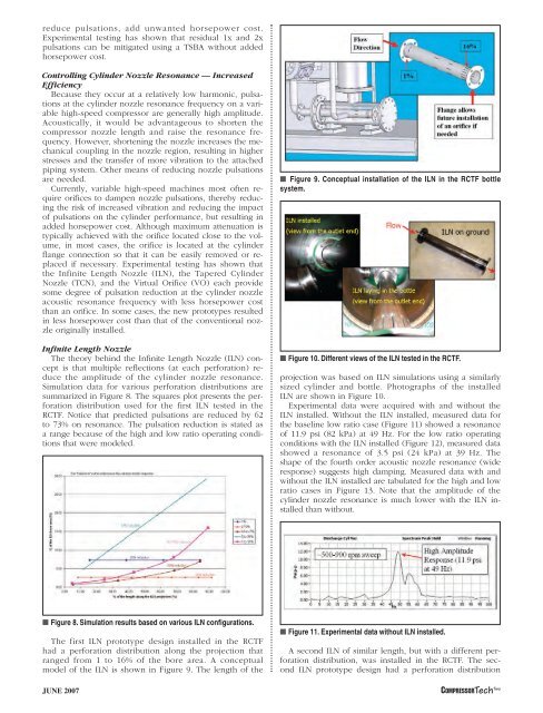
■ Figure 9. Conceptual installation of the ILN in the RCTF bottle<br />
system.<br />
■ Figure 10. Different views of the ILN tested in the RCTF.<br />
projection was based on ILN simulations using a similarly<br />
sized cylinder and bottle. Photographs of the installed<br />
ILN are shown in Figure 10.<br />
Experimental data were acquired with and without the<br />
ILN installed. Without the ILN installed, measured data for<br />
the baseline low ratio case (Figure 11) showed a resonance<br />
of 11.9 psi (82 kPa) at 49 Hz. For the low ratio operating<br />
conditions with the ILN installed (Figure 12), measured data<br />
showed a resonance of 3.5 psi (24 kPa) at 39 Hz. The<br />
shape of the fourth order acoustic nozzle resonance (wide<br />
response) suggests high damping. Measured data with and<br />
without the ILN installed are tabulated for the high and low<br />
ratio cases in Figure 13. Note that the amplitude of the<br />
cylinder nozzle resonance is much lower with the ILN installed<br />
than without.<br />
■ Figure 8. Simulation results based on various ILN configurations.<br />
The first ILN prototype design installed in the RCTF<br />
had a perforation distribution along the projection that<br />
ranged from 1 to 16% of the bore area. A conceptual<br />
model of the ILN is shown in Figure 9. The length of the<br />
JUNE 2007<br />
■ Figure 11. Experimental data without ILN installed.<br />
A second ILN of similar length, but with a different perforation<br />
distribution, was installed in the RCTF. The second<br />
ILN prototype design had a perforation distribution<br />
COMPRESSORTech Two