4. Installation Work - Portal - Fujitsu
4. Installation Work - Portal - Fujitsu
4. Installation Work - Portal - Fujitsu

You also want an ePaper? Increase the reach of your titles
YUMPU automatically turns print PDFs into web optimized ePapers that Google loves.
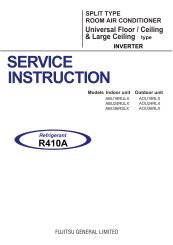
R410A
1. FUNDAMENTALS<br />
CONTENTS<br />
1-1 NEW REFRIGERANT R410A ................................................................................................. 01-01<br />
1-1-1 CHEMICAL PROPERTIES OF REFRIGERANTS ...................................................................... 01-01<br />
1-1-2 SATURATION TEMPERATURE AND SATURATION PRESSURE TABLES (R410A)..............<br />
01-02<br />
1-1-3 TEMPERATURE AND PRESSURE OF REFRIGERANT (GRAPH) .......................................... 01-03<br />
1-2 REFRIGERANT CYLINDERS ................................................................................................. 01-04<br />
1-2-1 LAWS..........................................................................................................................................<br />
01-04<br />
1-2-2 TYPES OF CONTAINERS..........................................................................................................<br />
01-04<br />
1-2-3 CONTAINER SPECIFICATIONS................................................................................................<br />
01-04<br />
1-2-4 CONTAINER INSCRIPTIONS AND LABELS ............................................................................. 01-05<br />
1-2-5 MOVING CONTAINERS.............................................................................................................<br />
01-05<br />
1-2-6 STORAGE OF CONTAINERS....................................................................................................<br />
01-06<br />
1-3 REFRIGERATOR OIL ............................................................................................................... 01-07<br />
1-3-1 TYPES OF REFRIGERATOR OIL ............................................................................................. 01-07<br />
1-3-2 MUTUAL SOLUBILITY OF REFRIGERANTOR OIL AND REFRIGERANT ............................... 01-07<br />
1-3-3 EFFECTS OF CONTAMINANTS................................................................................................<br />
01-07<br />
2. MATERIALS<br />
2-1 REFRIGERANT PIPES..............................................................................................................<br />
02-01<br />
2-1-1 QUALITY OF COPPER PIPES...................................................................................................<br />
02-01<br />
2-1-2 TYPES, GRADES, AND CODES................................................................................................<br />
02-01<br />
2-1-3 CHEMICAL COMPONENTS.......................................................................................................<br />
02-01<br />
2-1-4 MECHANICAL PROPERTIES .................................................................................................... 02-02<br />
2-1-5 CLASSIFICATIONS .................................................................................................................... 02-03<br />
2-1-6 DIMENSIONS ............................................................................................................................. 02-03<br />
2-2 CONNECTION PART.................................................................................................................<br />
02-06<br />
2-2-1 FLARE FITTING ENDS .............................................................................................................. 02-07<br />
2-2-2 FLARED PIPE ENDS..................................................................................................................<br />
02-08<br />
2-2-3 FLARE NUTS..............................................................................................................................<br />
02-09<br />
2-2-4 COPPER ALLOY BRAZING TYPE SOCKET FITTINGS ........................................................... 02-10<br />
2-2-5 BRAZING TYPE FITTINGS ........................................................................................................ 02-11<br />
2-3 THERMAL AND COLD INSULATION MATERIALS........................................................<br />
02-16<br />
2-3-1 SELECTING THERMAL AND COLD INSULATION MATERIALS..............................................<br />
02-16<br />
2-3-2 MAIN THERMAL AND COLD INSULATION MATERIALS ......................................................... 02-16<br />
3. TOOLS<br />
3-1 TOOLS............................................................................................................................................<br />
03-01<br />
3-1-1 REQUIRED TOOLS AND POINTS KEEP IN MIND DURING USE............................................<br />
03-01<br />
3-1-2 COPPER PIPE CUTTING TOOLS ............................................................................................. 03-02<br />
3-1-3 COPPER PIPE CONNECTION TOOLS ..................................................................................... 03-03<br />
3-1-4 COPPER PIPE BENDING TOOLS ............................................................................................. 03-04<br />
3-1-5 FLAIR JOINT TOOLS ................................................................................................................. 03-05<br />
3-1-6 BRAZING TOOLS.......................................................................................................................<br />
03-06<br />
3-1-7 VACUUM DRYING TOOLS ........................................................................................................ 03-07<br />
3-1-8 REFRIGERANT FITTING TOOLS .............................................................................................. 03-08<br />
3-1-9 OTHER TOOLS .......................................................................................................................... 03-09
<strong>4.</strong> INSTALLATION WORK<br />
CONTENTS<br />
4-1 INSTALLATION WORK AND SERVICING SAFETY.......................................................<br />
04-01<br />
4-2 INSTALLATION WORK PROCEDURE AND PRECAUTIONS .................................... 04-02<br />
4-3 IMPORTANT POINTS WHEN INSTAKKING INDOOR UNITS.....................................<br />
04-03<br />
4-3-1 INDOOR UNIT INSTALLATION ANGLE .................................................................................... 04-03<br />
4-4 REFRIGERANT PIPING WORK ............................................................................................ 04-04<br />
4-4-1 THREE BASICS PRINCIPLES OF REFRIGERANT PIPING WORK ........................................ 04-04<br />
4-4-2 PRECAUTIONS FOR REFRIGERANT PIPE WORK ................................................................. 04-05<br />
4-4-3 REFRIGERANT PIPE PROTECTION ........................................................................................ 04-06<br />
4-4-4 BRAZING....................................................................................................................................<br />
04-07<br />
4-4-5 BENDING ................................................................................................................................... 04-10<br />
4-4-6 REFRIGERANT PIPE FLUSHING ............................................................................................. 04-12<br />
4-4-7 FLARE WORK ............................................................................................................................ 04-13<br />
4-5 IMPORTANT POINTS WHEN INSTALLING SEPARATION TUBE............................<br />
04-16<br />
4-5-1 SEPARATION TUBE ANGLE.....................................................................................................<br />
04-16<br />
4-5-2 INTERVAL BETWEEN SEPARATION TUBES .......................................................................... 04-16<br />
4-6 IMPORTANT POINTS WHEN INSTALLING HEADERS................................................<br />
04-17<br />
4-7 AIR TIGHTNESS TESTING ..................................................................................................... 04-18<br />
4-8 PIPE INSULATION WORK ...................................................................................................... 04-22<br />
4-8-1 THICKNESS OF INSULATION MATERIAL ............................................................................... 04-22<br />
4-8-2 RECOMMENDED INSULATION PERFORMANCE ................................................................... 04-22<br />
4-8-3 TREATMENT OF JOINTS .......................................................................................................... 04-23<br />
4-9 VACUUM DRYING ..................................................................................................................... 04-24<br />
4-10 CHARGING REFRIGERANT.................................................................................................<br />
04-29<br />
4-10-1 PREVENTING COMPONENT ALTERATION .......................................................................... 04-29<br />
4-10-2 CHARGING REFRIGERANT USING A VACUUM ................................................................... 04-29<br />
4-10-3 CHARGING REFRIGERANT DURING OPERATION .............................................................. 04-29<br />
4-10-4 PREPARING FOR OPERATION..............................................................................................<br />
04-29<br />
4-11 REFRIGERANT LEAKAGE AMOUNT CAUTIONS.......................................................<br />
04-30<br />
4-12 REFRIGERANT RECOVERY................................................................................................<br />
04-33<br />
4-12-1 WHEN REPAIRING INDOOR UNIT PARTS AND PIPE JOINT LEAKS .................................. 04-33<br />
4-12-2 WHEN REPAIRING REFRIGERATION CYCLE PARTS OF OUTDOOR UNIT.......................<br />
04-33<br />
4-13 PUMP-DOWN.............................................................................................................................<br />
04-34<br />
4-13-1 PROCEDURE FOR PUMP-DOWN .......................................................................................... 04-34<br />
4-13-2 PUMP-DOWN FLOWCHART ................................................................................................... 04-35<br />
4-14 DRAIN PIPE WORK.................................................................................................................<br />
04-36<br />
4-14-1 OVERVIEW OF SPIRIT LEVEL ............................................................................................... 04-36<br />
4-14-2 GENERAL PRECAUTIONS FOR DRAIN PIPE WORK ........................................................... 04-36<br />
4-14-3 SELECTING THE DRAIN CAP POSITION .............................................................................. 04-38
CONTENTS<br />
5. ELECTRICAL WIRING WORK<br />
5-1 PRECAUTIONS WHEN WIRING COMMUNICATION LINES.......................................<br />
05-01<br />
5-1-1 COUNYERMEASURES FOR STATIC ELECTRICITY................................................................<br />
05-01<br />
5-1-2 PRECAUTIONS WHEN PERFORMING WIRING WORK .......................................................... 05-01<br />
5-1-3 MEASURING THE RESISTANCE OF THE COMMUNICATION LINE (MEASURE WITH BREAKER OFF) ...... 05-02<br />
5-1-4 PRECAUTIONS WHEN CONFIGURING SETTINGS ................................................................ 05-03<br />
5-1-5 PRECAUTIONS WHEN TURNING ON THE POWER ............................................................... 05-03<br />
5-2 GUIDELINES FOR SELECTING VRF COMMUNICATION CABLE ........................... 05-04<br />
5-3 METHODS FOR DETECTING INCORRECT CONNECTIONS (J-SERIES).............<br />
05-10
1. FUNDAMENTALS<br />
R410A
1. FUNDAMENTALS<br />
1-1 NEW REFRIGERANT R410A<br />
1-1-1 CHEMICAL PROPERTIES OF REFRIGERANTS<br />
CFC substitutes are being studied in many of the fields where CFCs were used, and two of the first CFC substitutes<br />
developed were HCFC and HFC.<br />
However, because HCFC was later sdded to the group of controlled substances, development now centers on HFC.<br />
The molecular design of HCFC and HFC adds a hydrogen atom to the CFC molecule so that the molecules will react<br />
with hydroxyl groups in the atmosphere and decompose in the troposphere before reaching the stratosphere, thereby<br />
reducing the destruction of the ozone layer.<br />
HCFC contains hydrogen and chlorine atoms inside the molecule and thus most molecules decompose in the troposphere,<br />
however, some molecules reach the stratosphere and cause slight ozone destruction. By contrast, HFC does<br />
not contain the chlorine atoms that destroy ozone, and thus even if HFC reaches the ozone layer, destruction of the<br />
layer does not take place.<br />
However, the life of HFC in the atmosphere is generally longer than HCFC, causing some concern with respect to<br />
global warming.<br />
R22 now in wide use is an HCFC type refrigerant, and as R22 is an ozone-destroying substance, it has been decided<br />
to substitute the HFC type refrigerants R407C and R410A for R22.<br />
Pipe work procedures for the new refrigerant models are generally the same as for R22, however, due to the properties<br />
of the refrigerants and the refrigerator oil, certain points require more caution than for air conditioners that use HCFC<br />
refrigerants, and special tools, piping materials, etc. are necessary for installation and service.<br />
1) Performance is almost equivalent to conventional R22.<br />
2) Like conventional R22, the new refrigerants are minimally toxic, chemically stable, and non-combustible.<br />
3) Operating pressure is about 1.6 times that of R22.<br />
4) The refrigerant mixture is pseudo-azeotropic, therefore there are almost no composition control problems.<br />
Conventional refrigerant<br />
(HCFC)<br />
New refrigerant (HFC)<br />
Refrigerant name R22 R407C R410A<br />
Chemical structure/components<br />
CHC1F 2<br />
HFC32/HFC125/HFC134a<br />
HFC32/HFC125<br />
Mixture ratio (%) 100 23/25/52 50/50<br />
Composition<br />
Simple refrigerant<br />
Non-azeotropic refrigerant<br />
mixture 2 gerant mixture<br />
Pseudo-azeotropic refri-<br />
3<br />
Boiling point (°C) 1<br />
-40.6 -43.6 -51.6<br />
Saturation pressure 26°C (Mpa) 0.9714<br />
1.126 1.608<br />
Ozone Depletion Potential (ODP)<br />
1<br />
0.034<br />
0<br />
0<br />
Global Warming Potential (GWP)<br />
1<br />
1700<br />
1700<br />
2000<br />
Safety class 1<br />
A1 A1/A1<br />
Refrigerator oil Mineral oil (SUNISO) Synthetic oil (Ether or Ester)<br />
Features<br />
Compound that includes<br />
chlorine, however, hydrogen<br />
reduces the level of ozone<br />
destruction<br />
New substitute refrigerant with hydrogen<br />
but no chlorine; causes no ozone destruction.<br />
1 : ASHRAE Refrigerant Data Summary (2000.11.) and values calculated using that data.<br />
2 : Non-azeotropic refrigerant mixture: mixture of multiple refrigerants with different boiling points.<br />
3 : Pseudo-azeotropic refrigerant mixture: mixture of multiple refrigerants with boiling points that are relatively close.<br />
- 01-01 -
1-1-2 Saturation temperature and saturation pressure tables (R410A)<br />
- 01-02 -<br />
0.0<br />
0.1<br />
0.2<br />
0.3<br />
0.4<br />
0.5<br />
0.6<br />
0.7<br />
0.8<br />
0.9<br />
1.0<br />
1.1<br />
1.2<br />
1.3<br />
1.4<br />
1.5<br />
1.6<br />
1.7<br />
1.8<br />
1.9<br />
2.0<br />
2.1<br />
2.2<br />
2.3<br />
2.4<br />
2.5<br />
2.6<br />
2.7<br />
2.8<br />
2.9<br />
3.0<br />
3.1<br />
3.2<br />
3.3<br />
3.4<br />
3.5<br />
3.6<br />
3.7<br />
3.8<br />
3.9<br />
<strong>4.</strong>0<br />
<strong>4.</strong>1<br />
-51.85<br />
-37.25<br />
-27.61<br />
-20.21<br />
-1<strong>4.</strong>12<br />
- 8.89<br />
- <strong>4.</strong>30<br />
- 0.17<br />
3.58<br />
7.02<br />
10.22<br />
13.21<br />
16.01<br />
18.66<br />
21.17<br />
23.55<br />
25.83<br />
28.01<br />
30.10<br />
32.11<br />
3<strong>4.</strong>04<br />
35.91<br />
37.72<br />
39.46<br />
41.16<br />
42.80<br />
4<strong>4.</strong>40<br />
45.95<br />
47.47<br />
48.94<br />
50.38<br />
51.78<br />
53.16<br />
5<strong>4.</strong>50<br />
55.81<br />
57.09<br />
58.35<br />
59.58<br />
60.79<br />
61.98<br />
63.14<br />
63.99<br />
-51.83<br />
-37.21<br />
-27.55<br />
-20.14<br />
-1<strong>4.</strong>04<br />
- 8.80<br />
- <strong>4.</strong>20<br />
- 0.06<br />
3.69<br />
7.15<br />
10.35<br />
13.34<br />
16.15<br />
18.80<br />
21.31<br />
23.70<br />
25.98<br />
28.16<br />
30.25<br />
32.26<br />
3<strong>4.</strong>20<br />
36.06<br />
37.87<br />
39.62<br />
41.31<br />
42.95<br />
4<strong>4.</strong>55<br />
46.10<br />
47.62<br />
49.09<br />
50.53<br />
51.93<br />
53.30<br />
5<strong>4.</strong>63<br />
55.94<br />
57.22<br />
58.48<br />
59.70<br />
60.91<br />
62.09<br />
63.25<br />
6<strong>4.</strong>38<br />
18<br />
19<br />
20<br />
21<br />
22<br />
23<br />
24<br />
25<br />
26<br />
27<br />
28<br />
29<br />
30<br />
31<br />
32<br />
33<br />
34<br />
35<br />
36<br />
37<br />
38<br />
39<br />
40<br />
41<br />
42<br />
43<br />
44<br />
45<br />
46<br />
47<br />
48<br />
49<br />
50<br />
51<br />
52<br />
53<br />
54<br />
55<br />
56<br />
57<br />
58<br />
59<br />
60<br />
61<br />
62<br />
63<br />
64<br />
65<br />
1.275<br />
1.314<br />
1.353<br />
1.394<br />
1.435<br />
1.477<br />
1.520<br />
1.563<br />
1.608<br />
1.654<br />
1.700<br />
1.747<br />
1.796<br />
1.845<br />
1.895<br />
1.946<br />
1.998<br />
2.051<br />
2.105<br />
2.160<br />
2.216<br />
2.273<br />
2.332<br />
2.391<br />
2.451<br />
2.513<br />
2.575<br />
2.639<br />
2.703<br />
2.769<br />
2.836<br />
2.904<br />
2.974<br />
3.044<br />
3.116<br />
3.189<br />
3.263<br />
3.338<br />
3.415<br />
3.493<br />
3.572<br />
3.653<br />
3.735<br />
3.818<br />
3.902<br />
3.988<br />
<strong>4.</strong>075<br />
<strong>4.</strong>164<br />
1.270<br />
1.308<br />
1.348<br />
1.388<br />
1.429<br />
1.471<br />
1.513<br />
1.557<br />
1.601<br />
1.647<br />
1.693<br />
1.740<br />
1.788<br />
1.837<br />
1.887<br />
1.938<br />
1.990<br />
2.043<br />
2.097<br />
2.152<br />
2.208<br />
2.265<br />
2.323<br />
2.382<br />
2.442<br />
2.503<br />
2.565<br />
2.629<br />
2.693<br />
2.759<br />
2.826<br />
2.894<br />
2.963<br />
3.034<br />
3.106<br />
3.178<br />
3.253<br />
3.328<br />
3.405<br />
3.483<br />
3.562<br />
3.643<br />
3.725<br />
3.808<br />
3.893<br />
3.979<br />
<strong>4.</strong>066<br />
<strong>4.</strong>155<br />
Saturation pressure (Mpa)<br />
Temp.<br />
(°C)<br />
Saturated liquid<br />
Saturated gas<br />
-30<br />
-29<br />
-28<br />
-27<br />
-26<br />
-25<br />
-24<br />
-23<br />
-22<br />
-21<br />
-20<br />
-19<br />
-18<br />
-17<br />
-16<br />
-15<br />
-14<br />
-13<br />
-12<br />
-11<br />
-10<br />
- 9<br />
- 8<br />
- 7<br />
- 6<br />
- 5<br />
- 4<br />
- 3<br />
- 2<br />
- 1<br />
0<br />
1<br />
2<br />
3<br />
4<br />
5<br />
6<br />
7<br />
8<br />
9<br />
10<br />
11<br />
12<br />
13<br />
14<br />
15<br />
16<br />
17<br />
0.1722<br />
0.1836<br />
0.1953<br />
0.2074<br />
0.2199<br />
0.2328<br />
0.2460<br />
0.2597<br />
0.2737<br />
0.2882<br />
0.3031<br />
0.3185<br />
0.3343<br />
0.3505<br />
0.3672<br />
0.3844<br />
0.4021<br />
0.4202<br />
0.4389<br />
0.4580<br />
0.4776<br />
0.4978<br />
0.5185<br />
0.5398<br />
0.5616<br />
0.5839<br />
0.6069<br />
0.6304<br />
0.6545<br />
0.6791<br />
0.7044<br />
0.7303<br />
0.7569<br />
0.7840<br />
0.8119<br />
0.8403<br />
0.8695<br />
0.9000<br />
0.930<br />
0.961<br />
0.993<br />
1.026<br />
1.059<br />
1.093<br />
1.128<br />
1.164<br />
1.200<br />
1.237<br />
0.1717<br />
0.1830<br />
0.1947<br />
0.2067<br />
0.2192<br />
0.2320<br />
0.2452<br />
0.2588<br />
0.2728<br />
0.2872<br />
0.3021<br />
0.3174<br />
0.3331<br />
0.3493<br />
0.3659<br />
0.3830<br />
0.4006<br />
0.4187<br />
0.4373<br />
0.4563<br />
0.4759<br />
0.4960<br />
0.5166<br />
0.5377<br />
0.5594<br />
0.5817<br />
0.6045<br />
0.6279<br />
0.6519<br />
0.6765<br />
0.7017<br />
0.7274<br />
0.7539<br />
0.7809<br />
0.8086<br />
0.8369<br />
0.8659<br />
0.8956<br />
0.926<br />
0.957<br />
0.989<br />
1.022<br />
1.055<br />
1.089<br />
1.123<br />
1.159<br />
1.195<br />
1.232<br />
(Pressure: Gauge pressure)<br />
Saturation pressure (Mpa)<br />
Temp.<br />
(°C)<br />
Saturated liquid<br />
Saturated gas<br />
Saturation<br />
pressure<br />
(Mpa)<br />
Saturation temperature (°C)<br />
Saturated liquid<br />
Saturated gas
1-1-3 Temperature and pressure of refrigerant (Graph)<br />
<strong>4.</strong>5<br />
<strong>4.</strong>0<br />
Saturated liquid pressure (MPa) (Gauge pressure)<br />
3.5<br />
3.0<br />
2.5<br />
2.0<br />
1.5<br />
1.0<br />
0.5<br />
0.0<br />
-30 -20 -10 0 10 20 30 40 50 60<br />
Saturated liquid temperature (°C)<br />
- 01-03 -
1-2 REFRIGERANT CYLINDERS<br />
1-2-1 Laws<br />
As a liquefied gas, R410A falls under the scope of the High-Pressure Gas Safety Law. Please refer to this law before using<br />
the refrigerant. The law establishes standards necessary for the prevention of accidents.<br />
1-2-2 Types of containers<br />
High-pressure gas containers used for refrigerants include welded containers, seamless containers, non-refillable containers,<br />
and service canisters. Welded containers are used for liquefied gas refrigerants. Most fluorocarbon refrigerants are distributed<br />
in welded containers. Seamless containers are used for high-pressure refrigerants and high-pressure gas, including<br />
fluorocarbon refrigerants such as FC14, CFC13, HFC23, and R503.<br />
Non-refillable containers are disposable and have been used in other countries for some time in the small-container<br />
(25 kg or less) sector. With the revision of the High-Pressure Gas Safety Law in April of 1997, non-refillable containers can<br />
now be used in Japan. Service canisters are small containers of 1 liter or less, and refilling is prohibited. Previously these<br />
containers were only approved for CFC12 and HFC134a, however, the revision of April 1st 1998 now allows filling with R404A,<br />
R407C, and R507A .The containable gases were also specified for each container type. (Table 2-1)<br />
Table 2-1: Types of containers and containable refrigerants<br />
Container type<br />
FC 1<br />
FC 2<br />
FC 3<br />
Test pressure<br />
3.0MPa<br />
<strong>4.</strong>0MPa<br />
5.0MPa<br />
Containable refrigerants<br />
CFC-12, HFC-134a, R500, R401A, R401B, CFC-115, R412A,<br />
HFC-218, R407D, HCFC-22, R502<br />
R900JA, R509A, R407C, R402B, R404A, R407A, R901JA, R507A,<br />
R402A, R407B, HFC-125, R407E, Gases corresponding to FC-1<br />
R410B, R410JA, R410A, JHFC-32<br />
Gases corresponding to FC-1 and FC-2<br />
1-2-3 Container specifications<br />
The High-Pressure Gas Law requires that high-pressure gas containers be inscribed, labeled, and colored. In addition, the<br />
number of mixed refrigerant types is increasing as new refrigerant substitutes are developed. To make identification easier<br />
and prevent accidental filling of the wrong refrigerant, the ARI in the United States has established Guideline N for the<br />
assignment of colors to refrigerant containers, and U.S. refrigerant manufacturers all use these colors.<br />
In Japan as well, colors equivalent to the ARI colors are used and a label is affixed to part of the container or the container is<br />
colored. The Japan Fluorocarbon Manufacturer's Association uses colors equivalent to the ARI colors for the three refrigerants<br />
R404A, R407C, and R410A (Figure 2-1).<br />
While not used for single refrigerants (R12, R22, R134a) that are filled as a gas phase, valves consisting of a siphon tube<br />
attached to a single valve exist for the purpose of filling mixed refrigerants (R404A, R407C, R401A) that are filled as a liquid<br />
phase. A valve with a siphon tube allows the container to be filled with liquid phase without tipping it over (Figure 2-2).<br />
Siphon tube<br />
Liquid<br />
R410A color is pink<br />
Figure 2-2<br />
Figure 2-1<br />
- 01-04 -
1-2-4 Container inscriptions and labels<br />
The following items are inscribed clearly and permanently in the order shown on a clearly visible part of the container where<br />
the wall is thick (such as on the shoulder). The container certification was discontinued in the revision of the High-Pressure<br />
Gas Control Law of December, 1991.<br />
- Symbol indicating that the container passed inspection and mark indicating the name of the inspector<br />
- Name or mark of container manufacturer<br />
- Type of gas to be filled (see Table 2-1)<br />
- Container symbol and number<br />
- Capacity (symbol V, in liters)<br />
- Weight (symbol W, in kilograms) not including valve and other accessories (detachable items only)<br />
- Year and month inspection passed<br />
- Pressure of pressure test (symbol TP, in Mpa)<br />
- Maximum filling pressure in container filled with compressed gas (symbol FP, in pascals)<br />
- Registered symbol and number of owner of container<br />
Inspector mark<br />
Symbol indicating container inspection passed<br />
Mark of container manufacturer<br />
Type of gas to be filled<br />
Container symbol and number<br />
V6.5<br />
1 2 3<br />
W6.1<br />
FC3<br />
4<br />
5<br />
10 97<br />
TP5.0M<br />
Registered number of container owner<br />
Pressure of pressure test (Mpa)<br />
Capacity (liters)<br />
Weight of container (kg)<br />
Year and month of pressure test<br />
Figure 2-3<br />
1-2-5 Moving containers<br />
The High-Pressure Gas Safety Law calls the transportation of high-pressure gas "moving". When moving high-pressure gas,<br />
the following measures stipulated by Ministerial ordinance must be taken to ensure safety.<br />
1) The vehicle that transports the filled container must put up a warning sign in an easily visible location.<br />
2) For containers carried on trucks and other vehicles, measures must be taken to prevent shock and valve damage due<br />
to toppling and falling. Containers must not be handled roughly.<br />
3) Filled containers must be kept at a constant temperature of no more than 40°C.<br />
4) Filled containers must not be carried together with dangerous materials stipulated in Section 7, Article 2 of the Fire<br />
Services Act.<br />
5) As a basic rule, filled containers should be loaded toward the front of the bed and be securely tied down with a rope,<br />
wire rope, luggage holder, or net in order to prevent shock and valve damage due to load scattering, falling, toppling,<br />
or vehicle collision.<br />
6) Except when unloading filled containers, the vehicle must not be parked in the vicinity of No. 1 Safety Buildings such as<br />
schools and hospitals, or in areas where No. 2 Safety Buildings (residences) are densely built. In addition, a safe<br />
parking location with little traffic must be selected. When parked, the driver is not to leave the vehicle except for meals<br />
or other situations where leaving the vehicle cannot be avoided.<br />
- 01-05 -
1-2-6 Storage of containers<br />
When storing 300 m 3 <br />
or more of fluorocarbon gas (for liquefied gas, 1 m3 is considered to be 10 kg, and thus this is<br />
equivalent to 3 tons), the storage location must be an established high-pressure gas storage area (type 2 storage area) that<br />
has been previously reported to the governor of the prefecture or other administrative division. When storing 3000 m 3 or<br />
more of fluorocarbon gas (30 tons or more of liquefied gas), the gas must be stored in a type 1 location that has been<br />
permitted in advance.<br />
- Storing 1.5 kg to 3 tons<br />
Reporting is not required, however, certain technical standards must be met:<br />
<br />
1) The container storage location must be clearly marked and a warning sign must be put up that is clearly visible from outside.<br />
2) Full containers must be kept separate from partially full containers so that the two can be distinguished.<br />
3) Objects other than gauges or other items required for work must not be placed in the storage location.<br />
4) Filled containers must be kept at a temperature that never exceeds 40°C.<br />
5) Measures must be taken to prevent shock and valve damage due to toppling and falling of filled containers, and filled<br />
containers must not be handled roughly.<br />
For 1.5 kg or less, there are no storage regulations.<br />
- 01-06 -
1-3 REFRIGERATOR OIL<br />
1-3-1 Types of refrigerator oil<br />
The type of refrigerator oil (lubricating oil) used in the compressor varies depending on the use, type, capacity, and refrigerant.<br />
The refrigerator oil base can be broadly classified into mineral oil and synthetic oil. The main oil types are described as follows.<br />
Mineral oil is generally used when the refrigerant is CFC or HCFC, and is based on naphthene or paraffin, or a blend of paraffin<br />
and alkyl benzene. HFC refrigerants will not dissolve into mineral oil, and thus a synthetic oil is generally used to heighten<br />
mutual solubility.<br />
Refrigerator oil<br />
Mineral oil<br />
Synthetic oil<br />
Naphthene base<br />
Paraffin base<br />
Alkyl benzene (AB)<br />
Polyvinyl ether (PVE)<br />
Polyphenyl ether (PPE)<br />
Polyalkylene glycol (PAG)<br />
Poly-ol ester (POE)<br />
Polycarbonate (PC)<br />
1-3-2 Mutual solubility of refrigerator oil and refrigerant<br />
Some fluorocarbon refrigerants have a feature of mutual solution with refrigerator oil, however, this depends on the type of oil<br />
and the type of refrigerant.<br />
When there is mutual solubility, the refrigerator oil blends together with the refrigerant and circulates with it during the<br />
refrigeration cycle, instead of only the refrigerant circulating. The oil collector in the compressor contains some dissolved<br />
refrigerant and the liquid refrigerant in the condenser contains a small amount of dissolved oil. When liquid refrigerant<br />
evaporates in the evaporator, the oil that was dissolved almost completely separates from the refrigerant. The system design<br />
takes care of this by adding a suction tube that returns the separated oil to the compressor. In addition, when the refrigerator is<br />
turned off, refrigerator oil collects not only in the compressor but also in suitable locations throughout the refrigerator cycle.<br />
One disadvantage of using mutually soluble oil is foaming phenomenon. When the refrigerator is turned off for a long time and<br />
the temperature of the oil in the compressor is lower than in other parts, refrigerant condenses and much of it dissolves into<br />
the oil. When the refrigerator is started in this state, the pressure drops and causes the dissolved refrigerant to suddenly<br />
evaporate, creating foam. This phenomenon is called foaming. At the same time as foaming occurs, a large amount of oil is<br />
spewed out from the discharge side, potentially leading to a compressor lubrication failure. To prevent foaming, some systems<br />
have a crankcase heater to warm the oil.<br />
1-3-3 Effects of contaminants<br />
1) Process oil (machining oil, assembly oil)<br />
If a refrigerating system that uses HFC refrigerant becomes contaminated with process oil such as machining or<br />
assembly oil, the process oil will separate, create sludge, and cause capillary plugging.<br />
2) Water<br />
If a refrigerating system that uses HFC refrigerant becomes contaminated with a large quantity of water, hydrolysis of<br />
the refrigerant and organic materials used in the compressor motor will occur, causing capillary plugging, compressor<br />
insulation failure, and other problems.<br />
3) Debris<br />
If a large quantity of debris enters a refrigerating system that uses HFC refrigerant, the refrigerator oil will separate<br />
and deteriorate, causing capillary plugging and insulation failure in the compressor and other parts.<br />
4) Air<br />
If a large quantity of air enters a refrigerating system that uses HFC refrigerant, the refrigerator oil will separate and<br />
deteriorate, causing capillary plugging and insulation failure in the compressor and other parts.<br />
5) Mixing of other refrigerants<br />
If a large quantity of a different type of refrigerant is mixed into a refrigerating system that uses HFC refrigerant,<br />
abnormal operating pressure and temperature will occur, causing damage to the system.<br />
6) Mixing of other refrigerator oils<br />
If a different type of refrigerator oil is mixed into a refrigerating system that uses HFC refrigerant, compressor<br />
lubrication failure and capillary plugging will occur, causing damage to the system. Even if a different purity or<br />
different grade of the same type of oil is used, or a different additive is used, compressor lubrication failure and<br />
capillary plugging may occur and cause damage to the system. For this reason, the refrigerator oil specified by the<br />
manufacturer must always be used.<br />
7) Flux<br />
If a chlorine residue from flux forms in the pipes, the pipes will deteriorate, and thus a flux with a low level of chlorine<br />
must be used. In addition, the flux should be removed after brazing. If water is added to the flux, use distilled water or<br />
other water that does not contain chlorine.<br />
- 01-07 -
2. MATERIALS<br />
R410A
2. MATERIALS<br />
2-1 REFRIGERANT PIPES<br />
2-1-1 Quality of copper pipes<br />
Refrigerant pipes use C1220 phosphorus deoxidized copper as specified in the Japanese Industrial<br />
Standard JIS H 3300 "Copper and copper alloy seamless pipes and tubes".<br />
1) No harmful cracks, dents, damage, or other defects.<br />
2) Truly round for practical purposes.<br />
3) Outer and inner pipe surface is clean and there is no harmful chlorine, sulfur, oxides, debris, cutting scraps, oil, or<br />
other material.<br />
Refrigerant piping recommended in other contries<br />
- USA<br />
- Austraria and New Zealand<br />
- Europe<br />
- China<br />
- Germany<br />
ASTM B280 C12200<br />
AS/NZS 1571<br />
BS28712/C106<br />
GB/T1889-1998<br />
DIN1787<br />
2-1-2 Types, grades, and codes<br />
Alloy<br />
number<br />
Type<br />
Shape<br />
Grade<br />
Code<br />
Name<br />
Remarks<br />
Characteristics and usage examples<br />
C1220<br />
Pipe<br />
Regular<br />
grade<br />
Special<br />
grade<br />
C1220T<br />
C1220TS<br />
Phosphorus<br />
deoxidized<br />
copper<br />
Good expandability, bendability, restrictability, weldability, corrosion<br />
resistance, and thermal conductivity. Even when C1220 is heated<br />
to high temperature in a reducing atmosphere, there is no concern<br />
that hydrogen embrittlement will occur. Used for heat exchangers,<br />
chemical industrial equipment, water supply, hot water supply, and<br />
gas pipes, etc.<br />
Dimension tolerance grades in JIS H 3300 are regular grade and the stricter special grade.<br />
Average diameter tolerances<br />
Outer diameter or inner diameter (mm)<br />
Grade<br />
Code<br />
4 or more<br />
up to 15<br />
More than<br />
15 up to 25<br />
More than<br />
25 up to 50<br />
More than<br />
50 up to 75<br />
More than<br />
75 up to 100<br />
More than More than<br />
100 up to 125 125 up to 150<br />
Regular<br />
grade<br />
Special<br />
grade<br />
C1220T<br />
C1220TS<br />
± 0.08 ± 0.09 ± 0.12 ± 0.15 ± 0.20 ± 0.27 ± 0.35<br />
± 0.05 ± 0.06 ± 0.08 ± 0.10 ± 0.13 ± 0.15 ± 0.18<br />
Average diameter is defined as the average of the maximum outer diameter and the minimum outer diameter, or the average<br />
of the maximum inner diameter and the minimum inner diameter, measured at any cross-section.<br />
2-1-3 Chemical components<br />
Alloy number<br />
Chemical component (%)<br />
Cu<br />
P<br />
C1220<br />
99.90 or more<br />
0.015 0.040<br />
- 02-01 -
2-1-4 Mechanical properties<br />
Grade<br />
Quality<br />
classification<br />
Code<br />
Tensile strength<br />
(N/mm 2 )<br />
Elongation<br />
(%)<br />
Hardness<br />
HR30T HR15T HRF<br />
Crystal particle<br />
size (mm)<br />
0<br />
C1220T-0<br />
C1220TS-0<br />
205 or more<br />
40 or more<br />
-<br />
60<br />
or less<br />
50<br />
or less<br />
0.025<br />
0.060<br />
C1220<br />
0L<br />
1/2H<br />
C1220T-0L<br />
C1220TS-0L<br />
C1220T-1/2H<br />
C1220TS-1/2H<br />
205 or more<br />
245<br />
325<br />
40 or more<br />
-<br />
-<br />
30<br />
60<br />
65<br />
or less<br />
-<br />
55<br />
or less<br />
-<br />
0.040<br />
or less<br />
H<br />
C1220T-H<br />
C1220TS-H<br />
315 or more<br />
-<br />
55<br />
or more<br />
-<br />
-<br />
Quality classification of copper pipes<br />
Quality<br />
classification<br />
F<br />
Summary<br />
As fabricated. No restrictions on mechanical properties. (Fabrication)<br />
0 Completely re-crystallized or annealed. Tensile strength value is lowest. (Zero-0)<br />
0L<br />
1/8H<br />
1/4H<br />
Annealed or lightly worked. Same tensile strength as 0. (Abbreviation of "Zero(0)-Light")<br />
Hardened to a tensile strength midway between quality classifications 0 and 1/4H.<br />
("H" is an abbreviation of "Hard".)<br />
Hardened to a tensile strength midway between quality classifications 1/8H and 1/2H.<br />
1/2H Hardened to a tensile strength midway between quality classifications 1/4H and 3/4H.<br />
3/4H<br />
H<br />
EH<br />
SH<br />
SR<br />
Hardened to a tensile strength midway between quality classifications 1/2H and H.<br />
Hardened to a tensile strength midway between quality classifications 3/4H and EH.<br />
Hardened to a tensile strength midway between quality classifications H and SH.<br />
(EH is an abbreviation of "Extra Hard")<br />
Hardened to the highest tensile strength. (SH is an abbreviation of "Spring Hard")<br />
Heat treated to release stress. (SR is an abbreviation of "Stress Release")<br />
There are two types of treatment: heat treatment and cold working.<br />
- 02-02 -
2-1-5 Classifications<br />
Classifications are based on JIS B 8607-2002 "Flare type and brazing type fittings for refrigerants"<br />
Classifications are type 1, type 2, and type 3 based on the maximum working pressure (design pressure).<br />
Type<br />
Type 1<br />
Type 2<br />
Type 3<br />
Maximum working<br />
pressure<br />
3.45MPa<br />
<strong>4.</strong>30MPa<br />
<strong>4.</strong>80MPa<br />
Example refrigerants (used at high pressure)<br />
R22, R134a, R404A, R407C, R507A, etc.<br />
R410A, etc.<br />
Refrigerants used at more than <strong>4.</strong>30 Mpa but not over <strong>4.</strong>80 Mpa.<br />
[Reference]<br />
1) In some cases, codes for the copper pipe wall thickness and compatible refrigerant appear<br />
on the surface of the heat insulation material.<br />
< Copper pipe wall thickness ><br />
Wall thickness<br />
(mm)<br />
Code<br />
< Compatible refrigerant display ><br />
Compatible refrigerant Code display<br />
0.8<br />
08<br />
Type 1<br />
R22, R407C<br />
1.0<br />
10<br />
Type 2<br />
R410A<br />
2) Some are also labeled to enable identification using the outer packaging.<br />
< Example of outer packaging labeling ><br />
(2): Both type 1 and type 2<br />
Compatible refrigerants: R22, R410A, R407C<br />
Copper pipe bore x wall thickness: 6.35 x 0.8 / 9.52 x 0.8<br />
2-1-6 Dimensions<br />
1) Wall thicknesses of copper pipes used for common refrigerants are shown in Table 2-1 and Table 2-2.<br />
These are extracted from JIS B 8607-2002 "Flare type and brazing type fittings for refrigerants".<br />
Important<br />
1) The pressure of substitute refrigerant R410A rises to 1.6 times that of R22. For this reason, be sure to use the<br />
appropriate copper pipe as indicated above.<br />
2) For reference, the equation for determining the required copper pipe wall thickness (C1220T) as stipulated in<br />
the refrigerant safety rule standards is given below.<br />
[Reference ]Equation t=[P DO / (2 a 0.8P)]<br />
t :Required wall thickness (mm)<br />
P :Maximum working pressure (design pressure, Mpa)<br />
DO :Standard outer diameter (mm)<br />
a :Basic allowable stress (N/mm) at 125°C<br />
:Corrosion allowance (0 mm)<br />
- 02-03 -
Extracted from JIS B 8607-200<br />
1. Scope of application: This table specifies types, dimensions, and tolerances of copper pipes for common refrigerant<br />
piping. However, refrigerant pipes inside factory assembled equipment do not need to conform to these values.<br />
2. Dimensions and tolerances of copper pipes: Dimensions and tolerances of copper pipes must conform to<br />
Table 2-1 or Table 2-2.<br />
Table 2-1: Dimensions and tolerances of common copper pipes for refrigerant piping<br />
Type<br />
Standard outer<br />
diameter (tolerance)<br />
D0 (mm)<br />
Wall thickness<br />
(tolerance)<br />
t (mm)<br />
Circularity<br />
tolerance<br />
(mm)<br />
Type<br />
Maximum working<br />
pressure P (MPa)<br />
Reference values<br />
Allowable tensile<br />
stressa (N/mm 2 )<br />
3.17 (± 0.03)<br />
0.70 (± 0.06)<br />
17.701<br />
<strong>4.</strong>76 (± 0.03)<br />
0.70 (± 0.06)<br />
11.000<br />
6.00 (± 0.03)<br />
0.70 (± 0.06)<br />
8.492<br />
6.35 (± 0.03)<br />
0.80 (± 0.06)<br />
Type 3<br />
9.246<br />
8.00 (± 0.03)<br />
0.80 (± 0.06)<br />
7.173<br />
9.52 (± 0.03)<br />
0.80 (± 0.06)<br />
5.945<br />
10.00 (± 0.03)<br />
0.80 (± 0.06)<br />
5.641<br />
0<br />
and<br />
0L<br />
12.70 (± 0.03)<br />
15.88 (± 0.03)<br />
19.05 (± 0.03)<br />
22.22 (± 0.03)<br />
0.80 (± 0.06)<br />
1.00 (± 0.09)<br />
1.00 (± 0.09)<br />
1.15 (± 0.09)<br />
-<br />
Type 2<br />
<strong>4.</strong>378<br />
<strong>4.</strong>376<br />
3.616<br />
3.563<br />
33<br />
(Allowable tensile<br />
stress at 125°C)<br />
25.40 (± 0.04)<br />
1.30 (± 0.09)<br />
3.522<br />
28.58 (± 0.04)<br />
1.45 (± 0.10)<br />
3.490<br />
31.75 (± 0.04)<br />
1.60 (± 0.10)<br />
3.465<br />
3<strong>4.</strong>92 (± 0.04)<br />
1.75 (± 0.10)<br />
Type 1<br />
3.445<br />
38.10 (± 0.05)<br />
1.90 (± 0.10)<br />
3.428<br />
41.28 (± 0.05)<br />
2.10 (± 0.13)<br />
3.500<br />
4<strong>4.</strong>45 (± 0.05)<br />
2.25 (± 0.13)<br />
3.481<br />
50.80 (± 0.05)<br />
2.55 (± 0.18)<br />
3.455<br />
53.98 (± 0.05)<br />
2.75 (± 0.18)<br />
3.505<br />
Remarks<br />
1. The standard outer diameter tolerance is the allowed limit of the difference between the standard<br />
outer diameter and the average of the maximum outer diameter and the minimum outer diameter<br />
measured at any cross-section of the pipe.<br />
2. The circularity tolerance does not apply to pipes of quality classification 0 and 0L, and coil-wound pipes.<br />
3. Copper pipes not listed in this table are specified by the special class of JIS H 3300.<br />
<strong>4.</strong> Copper pipes with an outer diameter of 10.00 mm or less can also be used as a type 1 or 2 pipe.<br />
Copper pipes with a diameter of 12.70 and 15.88 mm can also be used as a type 1 pipe.<br />
- 02-04 -
Table 2-2: Dimensions and tolerances of common copper pipes for refrigerant piping<br />
Type<br />
Standard outer<br />
diameter (tolerance)<br />
D0 (mm)<br />
Wall thickness<br />
(tolerance)<br />
t (mm)<br />
Circularity<br />
tolerance<br />
(mm)<br />
Type<br />
Reference values<br />
Maximum working<br />
pressure P (MPa)<br />
Allowable tensile<br />
stressa (N/mm 2 )<br />
3.17 (± 0.03)<br />
0.70 (± 0.06)<br />
0.03 or less<br />
32.720<br />
<strong>4.</strong>76 (± 0.03)<br />
0.70 (± 0.06)<br />
0.04 or less<br />
20.528<br />
6.00 (± 0.03)<br />
0.70 (± 0.06)<br />
0.05 or less<br />
15.698<br />
6.35 (± 0.03)<br />
0.80 (± 0.06)<br />
0.05 or less<br />
17.092<br />
8.00 (± 0.03)<br />
0.80 (± 0.06)<br />
0.07 or less<br />
13.260<br />
9.52 (± 0.03)<br />
10.00 (± 0.03)<br />
0.80 (± 0.06)<br />
0.80 (± 0.06)<br />
0.08 or less<br />
0.08 or less<br />
Type 3<br />
10.990<br />
10.427<br />
12.70 (± 0.03)<br />
0.80 (± 0.06)<br />
0.11 or less<br />
8.092<br />
1/2H<br />
or<br />
H<br />
15.88 (± 0.03)<br />
19.05 (± 0.03)<br />
22.22 (± 0.03)<br />
1.00 (± 0.09)<br />
1.00 (± 0.09)<br />
1.00 (± 0.09)<br />
0.13 or less<br />
0.16 or less<br />
0.23 or less<br />
8.090<br />
6.684<br />
5.695<br />
61<br />
(Allowable tensile<br />
stress at 125°C)<br />
25.40 (± 0.04)<br />
1.00 (± 0.09)<br />
0.26 or less<br />
<strong>4.</strong>959<br />
28.58 (± 0.04)<br />
31.75 (± 0.04)<br />
1.00 (± 0.09)<br />
1.10 (± 0.09)<br />
0.29 or less<br />
0.32 or less<br />
Type 2<br />
<strong>4.</strong>391<br />
<strong>4.</strong>347<br />
3<strong>4.</strong>92 (± 0.04)<br />
1.10 (± 0.09)<br />
0.35 or less<br />
3.942<br />
38.10 (± 0.05)<br />
1.15 (± 0.09)<br />
0.39 or less<br />
3.773<br />
41.28 (± 0.05)<br />
1.20 (± 0.09)<br />
0.42 or less<br />
3.630<br />
4<strong>4.</strong>45 (± 0.05)<br />
1.25 (± 0.09)<br />
0.45 or less<br />
3.509<br />
50.80 (± 0.05)<br />
53.98 (± 0.05)<br />
1.40 (± 0.13)<br />
1.50 (± 0.15)<br />
0.51 or less<br />
0.54 or less<br />
Type 1<br />
3.434<br />
3.467<br />
63.50 (± 0.05)<br />
1.75 (± 0.15)<br />
0.64 or less 3.438<br />
66.68 (± 0.05)<br />
1.85 (± 0.15)<br />
0.67 or less<br />
3.461<br />
76.20 (± 0.05)<br />
2.10 (± 0.18)<br />
0.77 or less<br />
3.438<br />
79.38 (± 0.05)<br />
2.20 (± 0.18)<br />
0.80 or less<br />
3.457<br />
Remarks<br />
1. The standard outer diameter tolerance is the allowed limit of the difference between the standard<br />
outer diameter and the average of the maximum outer diameter and the minimum outer diameter<br />
measured at any cross-section of the pipe.<br />
2. The circularity tolerance is the difference between the diameter and the shortest diameter measured<br />
at any cross-section of the pipe.<br />
3. Copper pipes not listed in this table are specified by the special class of JIS H 3300.<br />
<strong>4.</strong> Copper pipes with a standard diameter of 25.40 mm or less can also be used as a type 1 and 2 pipe.<br />
Copper pipes with a diameter of 28.58 and 31.75 mm can also be used as a type 1 pipe.<br />
- 02-05 -
2-2 Connection Part<br />
Flare fittings for refrigerants (JIS B 8607-2002)<br />
Flare fittings for copper pipes can be used to connect pipes of nominal diameter 3/4 (outer diameter of copper pipe<br />
19.05 mm) or less.<br />
For pipe diameters larger than the above, a flange fitting or brazing fitting is used. Before using fittings, verify that no<br />
contaminants adhere to the inside of the pipes that form the refrigerant circuit.<br />
Refrigerant flare fittings are classified as type 1 (3.45 Mpa) and type 2 (<strong>4.</strong>30 Mpa) depending on the maximum working<br />
pressure (design pressure). Type 1 corresponds to R22 pressure and has been in use for some time. Type 2 corresponds<br />
to R410A pressure and thus is a newly established type. Type 2 is approved for use only in locations that are not subject<br />
to external forces such as vibrational forces or bending. Table 2-3 indicates the existence or not of applicable standards<br />
for each working pressure. Select a suitable fitting for your working pressure (for the refrigerant that will be used).<br />
Table 2-3: Varieties of fittings, types and maximum working pressures (design pressures)<br />
Fitting variety and type<br />
Maximum working pressure<br />
Type 1<br />
3.45Mpa<br />
Type 2<br />
<strong>4.</strong>30Mpa<br />
Type 3<br />
<strong>4.</strong>80Mpa<br />
Flare fittings<br />
Not subject to external forces<br />
such as vibrational force or<br />
bending<br />
Non-toxic and non-combustible<br />
refrigerants<br />
Toxic and combustible refrigerants<br />
Table<br />
2-6<br />
Table<br />
2-6<br />
Table<br />
2-6<br />
Subject to external forces such as external vibrational force or bending.<br />
However, cannot be used for toxic and combustible refrigerants.<br />
Table<br />
2-6<br />
Copper alloy brazing fitting<br />
Same as<br />
type 3<br />
Same as<br />
type 3<br />
Table<br />
2-8<br />
Standard outside diameter of copper pipe: 3.17 mm to 22.22 mm<br />
Same as<br />
type 3<br />
Same as<br />
type 3<br />
Table<br />
2-11<br />
Brazing fitting<br />
Standard outside diameter of copper pipe: 25.40 mm to 28.58 mm<br />
Same as<br />
type 2<br />
Table<br />
2-11<br />
Standard outside diameter of copper pipe: 31.75 mm to 79.38 mm<br />
Table<br />
2-11<br />
Remarks<br />
1. "X" in the table indicates that the type cannot be used.<br />
2. Examples of refrigerants classified by maximum working pressure type are shown in the following table.<br />
Type<br />
Type 1<br />
Type 2<br />
Type 3<br />
Maximum working<br />
pressure<br />
3.45MPa<br />
<strong>4.</strong>30MPa<br />
<strong>4.</strong>80MPa<br />
Refrigerant examples (used at high pressure)<br />
R22, R134a, R404A, R407C, R507A, etc.<br />
R410A, etc.<br />
Refrigerants used at more than <strong>4.</strong>30 Mpa but not over <strong>4.</strong>80 MPa.<br />
- 02-06 -
Table of usage of refrigerant flare fittings by working pressure<br />
Nominal<br />
Outer diameter<br />
of applicable<br />
pipe (mm)<br />
Flare fitting end<br />
Both type 1 and type 2<br />
Flared pipe end<br />
Flare nut<br />
Type 1 Type 2 Type 1 Type 2<br />
3.45MPa <strong>4.</strong>30MPa 3.45MPa <strong>4.</strong>30MPa<br />
1/4<br />
6.35<br />
3/8<br />
9.52<br />
1/2<br />
12.70<br />
5/8<br />
15.88<br />
3/4<br />
19.05<br />
2-2-1 Flare fitting ends<br />
The shape and dimensions of type 1 (3.45 MPa) and type 2 (<strong>4.</strong>30 MPa) are the same, and thus<br />
previously used fitting ends can be used.<br />
The shapes and dimensions are shown in Table 2-<strong>4.</strong><br />
Table 2-4: Shape and dimensions of flare fitting end<br />
L 1<br />
L 2<br />
d<br />
45°<br />
45° 46° (Flare seat)<br />
6.3<br />
25<br />
1.6<br />
Ø D1<br />
Ø D2<br />
Ø D3<br />
25<br />
Flare fitting ends<br />
Completely threaded part<br />
L<br />
Units: mm<br />
Nominal<br />
Outer diameter<br />
of applicable<br />
pipe<br />
Nominal screw<br />
d<br />
D 1<br />
0<br />
-0.15<br />
D 2 D 3 L<br />
L 1<br />
(minimum)<br />
L 2<br />
1/4<br />
6.35<br />
7/16 - 20UNF<br />
<strong>4.</strong>8<br />
5.5<br />
9.2<br />
13.5<br />
11.3<br />
3.7<br />
3/8<br />
9.52<br />
5/8 - 18UNF<br />
7.0<br />
8.0<br />
13.5<br />
16.5<br />
1<strong>4.</strong>0<br />
<strong>4.</strong>8<br />
1/2<br />
12.70<br />
3/4 - 16UNF<br />
10.0<br />
11.0<br />
16.0<br />
19.5<br />
16.8<br />
5.5<br />
5/8<br />
15.88<br />
7/8 - 14UNF<br />
12.5<br />
13.5<br />
19.0<br />
23.0<br />
19.9<br />
6.0<br />
3/4<br />
19.05<br />
1-1/16 - 14UNS<br />
16.0<br />
18.0<br />
2<strong>4.</strong>0<br />
26.5<br />
23.4<br />
6.0<br />
1) The dimensions of the flare fitting end are the same for type 1 and type 2.<br />
2) Screws used for pipe fittings are specified by JIS B 0208 (Unified fine screw threads).<br />
However, 1 1/16 - 14UNS screws are specified by JIS B 8607 <strong>4.</strong>1h.<br />
- 02-07 -
2-2-2 Flared pipe ends<br />
Flared pipe ends are classified by working pressure as type 1 (3.45 Mpa) and type 2 (<strong>4.</strong>30 Mpa). Type 1 flared pipe<br />
ends are the same as the conventional flared pipe ends. Each type 2 flared pipe end has a larger diameter and<br />
nominal diameter at A (the outer diameter at the trumpet shaped end).<br />
The shape and dimensions are shown in Table 2-5.<br />
Table 2-5: Shape and dimensions of flared pipe ends<br />
45° ±2°<br />
R0.4 0.8<br />
90° ±2°<br />
ØA<br />
ØD 0<br />
Flared pipe ends<br />
Nominal<br />
Outer diameter<br />
of pipe<br />
D 0<br />
A +0<br />
-0.4<br />
Units: mm<br />
Type 1 Type 2<br />
1/4<br />
6.35<br />
9.0<br />
9.1<br />
3/8<br />
9.52<br />
13.0<br />
13.2<br />
1/2<br />
12.70<br />
16.2<br />
16.6<br />
5/8<br />
15.88<br />
19.4<br />
19.7<br />
3/4<br />
19.05<br />
23.3<br />
2<strong>4.</strong>0<br />
Remarks 1. Flared copper pipes must be made of O or OL material.<br />
2. Deviation of the flared pipe end must be no more than 0.4 mm.<br />
3. A type 1 flared pipe end is used when a type 1 flare nut is used for connection.<br />
A type 2 flared pipe end is used when a type 2 flare nut is used for connection.<br />
- 02-08 -
2-2-3 Flare nuts<br />
Flare nuts with nominal diameters 1/4, 3/8, and 3/4 are the same for type 1 (3.45 Mpa) and type 2 (<strong>4.</strong>30 Mpa).<br />
Flare nuts with nominal diameters 1/2 and 5/8 are classified by working pressure as type 1 and type 2, and the<br />
dimension B spanned by the wrench (distance between the two opposite sides of the nut) is larger on type 2.<br />
The shape and dimensions are shown in Table 2.-6.<br />
The flare nut should use the specified one by our company or the one attach to the units.<br />
Table 2-6: Shape and dimensions of flare nut<br />
B<br />
L<br />
H<br />
Approx. 120°<br />
ØC<br />
6.3<br />
ØD<br />
ØE<br />
d<br />
25<br />
45°(minimum)<br />
J<br />
Completely threaded part T<br />
1.6<br />
Part A C0.5<br />
43° 45° (Flare seat)<br />
ØG<br />
Expanded view of part A<br />
R1<br />
Flare nuts<br />
R Approx.0.2<br />
Type 1 flare nut dimensions<br />
Nominal<br />
Outer diameter<br />
of applicable pipe<br />
Nominal screw<br />
d<br />
B 0<br />
-0.6<br />
E<br />
D +0.1<br />
0 H ±0.8 J L ±0.5 T G<br />
(Minimum)<br />
Units: (mm)<br />
C<br />
(Approx.)<br />
1/4<br />
6.35<br />
7/16 - 20UNF<br />
17<br />
6.5<br />
13<br />
12<br />
6.3<br />
15<br />
9.0<br />
9.7<br />
16.5<br />
3/8<br />
9.52<br />
5/8 - 18UNF<br />
22<br />
9.7<br />
20<br />
16<br />
7.8<br />
18<br />
10.8<br />
1<strong>4.</strong>3<br />
21<br />
1/2<br />
12.70<br />
3/4 - 16UNF<br />
24<br />
12.9<br />
20<br />
16<br />
10.0<br />
22<br />
13<br />
17.3<br />
23<br />
5/8<br />
15.88<br />
7/8 - 14UNF<br />
27<br />
16.0<br />
24<br />
20<br />
12.5<br />
26<br />
15.5<br />
20.2<br />
26<br />
3/4<br />
19.05<br />
1-1/16 - 14UNS<br />
36<br />
19.2<br />
28<br />
24<br />
16.0<br />
30<br />
19<br />
25<br />
34<br />
Type 2 flare nut dimensions<br />
Nominal<br />
Outer diameter<br />
of applicable pipe<br />
Nominal screw<br />
d<br />
B 0<br />
-0.6<br />
E<br />
D +0.1<br />
0 H ±0.8 J L ±0.5 T G<br />
(Minimum)<br />
Units: (mm)<br />
C<br />
(Approx.)<br />
1/4<br />
6.35<br />
7/16 - 20UNF<br />
17<br />
6.5<br />
13<br />
12<br />
6.3<br />
15<br />
9.0<br />
9.7<br />
16.5<br />
3/8<br />
9.52<br />
5/8 - 18UNF<br />
22<br />
9.7<br />
20<br />
16<br />
7.8<br />
18<br />
10.8<br />
1<strong>4.</strong>3<br />
21<br />
1/2<br />
12.70<br />
3/4 - 16UNF<br />
26<br />
12.9<br />
23<br />
19<br />
10.0<br />
22<br />
13<br />
17.3<br />
26<br />
5/8<br />
15.88<br />
7/8 - 14UNF<br />
29<br />
16.0<br />
25<br />
22<br />
12.5<br />
26<br />
15.5<br />
20.2<br />
28<br />
3/4<br />
19.05<br />
1-1/16 - 14UNS<br />
36<br />
19.2<br />
28<br />
24<br />
16.0<br />
30<br />
19<br />
25<br />
34<br />
Remarks For both type 1 and type 2, the thread-cutting recess indicated in the enlarged view of part A can be omitted,<br />
however, the length J of the completely threaded part must not be shortened.<br />
1) Bolts used for pipe fittings are specified in JIS B 0208 (Unified fine screw threads).<br />
However, 1 1/16 - 14 UNS bolts are specified in JIS B 8607 <strong>4.</strong>1h.<br />
- 02-09 -
2-2-4 Copper alloy brazing type socket fittings<br />
Copper alloy brazing type fittings can be used to connect copper pipes of nominal diameter 7/8<br />
(outer diameter 22.22 mm) or less.<br />
Pipes larger than this are connected with flange fittings or brazing type fittings.<br />
Copper alloy brazing type fittings can be used mutually for any working pressure up to <strong>4.</strong>8 Mpa; there are no type<br />
classifications by working pressure.<br />
Shape and dimensions are shown in Table 2-8.<br />
Table 2-7: Copper alloy brazing type socket fittings by working pressure list<br />
Nominal<br />
Outer diameter<br />
of copper pipe<br />
(mm)<br />
Type 3 (<strong>4.</strong>8 Mpa)<br />
Remarks<br />
1/8 7/8 3.17 22.22<br />
Can be used for <strong>4.</strong>80 Mpa or less<br />
Table 2-8: Shape and dimensions of flare copper alloy brazing type socket fittings<br />
25<br />
ØO<br />
ØF<br />
ØE<br />
Before the brazing<br />
25 6.3<br />
C<br />
G<br />
K<br />
25<br />
After the brazing<br />
Access valve<br />
Units: (mm)<br />
Nominal<br />
A<br />
B<br />
Standard outer<br />
diameter of connected<br />
copper pipe<br />
D0<br />
Standard inner<br />
diameter F<br />
(allowed tolerance)<br />
Minimum length<br />
G<br />
K<br />
Minimum outer<br />
diameter<br />
E<br />
Bevel<br />
C<br />
Inner diameter<br />
O<br />
1/8 3.17 3.27 (±0.03) 5 6 5.6 -<br />
2.4<br />
3/16<br />
<strong>4.</strong>76 <strong>4.</strong>86 (±0.03) 5 6 7.2 -<br />
3.9<br />
6<br />
6.00 6.10 (±0.03) 6 7 8.3 -<br />
5.0<br />
1/4<br />
6.35 6.45 (±0.03) 6 7 8.7 -<br />
5.3<br />
8<br />
8.00 8.10 (±0.03) 7 8 10.2 0.3 6.8<br />
3/8<br />
9.52 9.62 (±0.03) 7 8 12.2 0.3 8.2<br />
10<br />
10.00<br />
10.10 (±0.03)<br />
7<br />
8<br />
12.7<br />
0.3<br />
8.6<br />
1/2<br />
12.70<br />
12.80 (±0.03)<br />
8<br />
9<br />
15.3<br />
0.3<br />
11.0<br />
5/8<br />
15.88<br />
16.00 (±0.03)<br />
8<br />
9<br />
18.8<br />
0.3<br />
1<strong>4.</strong>0<br />
3/4<br />
19.05<br />
19.19 (±0.03)<br />
10<br />
11<br />
21.9<br />
0.3<br />
17.0<br />
7/8<br />
22.22<br />
22.36 (±0.03)<br />
10<br />
11<br />
2<strong>4.</strong>9<br />
0.3<br />
20.0<br />
Remarks 1. The maximum working pressure (design pressure) of the copper alloy brazing type fittings shown in this<br />
table is <strong>4.</strong>80 Mpa. The fittings are the same for types 1, 2, and 3 .<br />
2. Either an A nominal size or a B nominal size is used. A or B may be added after a dimension as needed<br />
to distinguish the nominal size type.<br />
3. When used as a male fitting, outer diameter E can match the inner diameter of the copper pipe.<br />
<strong>4.</strong> Finish the end surface so that it is smooth.<br />
- 02-10 -
2-2-5 Brazing type fittings<br />
Types of brazing type fittings<br />
Brazing type fittings are listed in Table 2-10 based on the overall shape and type of connector, and are shown<br />
in Figures 2-1 to 2-6.<br />
Brazing type fittings are classified as type 1, type 2, and type 3 based on the working pressure. Useable working<br />
pressures and corresponding copper pipe diameters are shown in Table 2-9.<br />
Table 2-9: Brazing type fittings by working pressure list<br />
Standard outer<br />
diameter of connected<br />
copper pipe<br />
(mm)<br />
Type 1 Type 2<br />
3.45Mpa<br />
<strong>4.</strong>30Mpa<br />
Type 3<br />
<strong>4.</strong>80Mpa<br />
Remarks<br />
3.17 22.22<br />
Can be used at pressures of <strong>4.</strong>80 Mpa or less<br />
25.40 28.58 Can be used at pressures of <strong>4.</strong>30 Mpa or less<br />
31.75 79.38<br />
Can be used at pressures of 3.45 Mpa or less.<br />
Table 2-10: Types of brazing type fittings<br />
Type Code Connector<br />
Example diagram<br />
T<br />
T<br />
Female<br />
Figure 2-1<br />
90° elbow A<br />
90EA<br />
Female<br />
Figure 2-2<br />
90° elbow B<br />
90EB<br />
Female, male<br />
Figure 2-3<br />
45° elbow<br />
45EA<br />
Female<br />
Figure 2-4<br />
Socket<br />
S<br />
Female<br />
Figure 2-5<br />
Reducing socket<br />
RS<br />
Female<br />
Figure 2-6<br />
Y<br />
X<br />
X<br />
X<br />
X<br />
Figure 2-1: T<br />
Figure 2-2: 90o elbow A<br />
- 02-11 -
X<br />
Z<br />
X<br />
X<br />
Figure 2-3: 90° elbow B<br />
Figure 2-4: 45° elbow<br />
X<br />
Z<br />
Figure 2-5: Socket<br />
Figure 2-6: Reducing socket<br />
Dimensions and tolerances of brazing type fittings<br />
Brazing type fittings for connected copper pipes with standard outer diameters of 22.22 mm or less can also be<br />
used as type 1 and type 2. Brazing type fittings for diameters of 25.40 to 28.58 mm can also be used as type 1.<br />
Dimensions and tolerances of brazing type fittings are shown in Table 2-11.<br />
Connector<br />
Male<br />
Female<br />
K<br />
G<br />
Ø A<br />
Ø F<br />
- 02-12 -<br />
Figure 2-7
Table 2-11: Dimensions and tolerances of brazing type fittings<br />
Units: (mm)<br />
Standard<br />
outer diameter<br />
of<br />
connected<br />
copper pipe<br />
D0<br />
Male<br />
Standard outer<br />
diameter (tolerance)<br />
A<br />
Connector<br />
Female<br />
Standard outer<br />
diameter (tolerance)<br />
F<br />
Minimum<br />
insertion<br />
depth<br />
K<br />
G<br />
Ellipse<br />
value<br />
Minimum<br />
connector<br />
thickness<br />
Maximum working<br />
pressure<br />
(design pressure)<br />
P Mpa<br />
Type<br />
3.17<br />
3.17 (±0.03)<br />
3.27 (±0.03)<br />
6<br />
5<br />
0.04 or less<br />
0.50<br />
<strong>4.</strong>80<br />
Type 3<br />
<strong>4.</strong>76<br />
<strong>4.</strong>76 (±0.03)<br />
<strong>4.</strong>86 (±0.03)<br />
6<br />
5<br />
0.05 or less<br />
0.50<br />
6.00<br />
6.00 (±0.03)<br />
6.10 (±0.03)<br />
7<br />
6<br />
0.05 or less<br />
0.50<br />
6.35<br />
6.35 (±0.03)<br />
6.45 (±0.03)<br />
7<br />
6<br />
0.06 or less<br />
0.50<br />
8.00<br />
8.00 (±0.03)<br />
8.10 (±0.03)<br />
8<br />
7<br />
0.06 or less<br />
0.50<br />
9.52<br />
9.52 (±0.03)<br />
9.62 (±0.03)<br />
8<br />
7<br />
0.08 or less<br />
0.60<br />
10.00<br />
10.00 (±0.03)<br />
10.10 (±0.03)<br />
8<br />
7<br />
0.08 or less<br />
0.60<br />
12.70<br />
12.70 (±0.03)<br />
12.81 (±0.03)<br />
9<br />
8<br />
0.10 or less<br />
0.70<br />
15.88<br />
15.88 (±0.03)<br />
16.00 (±0.03)<br />
9<br />
8<br />
0.13 or less<br />
0.80<br />
19.05<br />
19.05 (±0.03)<br />
19.19 (±0.03)<br />
11<br />
10<br />
0.15 or less<br />
0.80<br />
22.22<br />
22.22 (±0.03)<br />
22.36 (±0.03)<br />
11<br />
10<br />
0.16 or less<br />
0.90<br />
25.40<br />
25.40 (±0.04)<br />
25.56 (±0.04)<br />
13<br />
12<br />
0.18 or less<br />
0.95<br />
<strong>4.</strong>30<br />
Type 2<br />
28.58<br />
28.58 (±0.04)<br />
28.75 (±0.04)<br />
13<br />
12<br />
0.20 or less<br />
1.00<br />
31.75<br />
31.75 (±0.04)<br />
31.93 (±0.04)<br />
13<br />
12<br />
0.22 or less<br />
1.05<br />
3.45 Type 1<br />
3<strong>4.</strong>92<br />
3<strong>4.</strong>92 (±0.04)<br />
35.11 (±0.04)<br />
13<br />
12<br />
0.24 or less<br />
1.20<br />
38.10<br />
38.10 (±0.05)<br />
38.31 (±0.05)<br />
15<br />
14<br />
0.27 or less<br />
1.25<br />
41.28<br />
41.28 (±0.05)<br />
41.50 (±0.05)<br />
15<br />
14<br />
0.29 or less<br />
1.25<br />
4<strong>4.</strong>45<br />
4<strong>4.</strong>45 (±0.05)<br />
4<strong>4.</strong>68 (±0.05)<br />
15<br />
14<br />
0.31 or less<br />
1.25<br />
50.80<br />
50.80 (±0.05)<br />
51.03 (±0.05)<br />
17<br />
16<br />
0.31 or less<br />
1.40<br />
53.98<br />
53.98 (±0.05)<br />
5<strong>4.</strong>22 (±0.05)<br />
17<br />
16<br />
0.32 or less<br />
1.50<br />
63.50<br />
63.50 (±0.03)<br />
63.77 (±0.05)<br />
19<br />
18<br />
0.38 or less<br />
1.75<br />
66.68<br />
66.68 (±0.03)<br />
66.96 (±0.05)<br />
22<br />
21<br />
0.40 or less<br />
1.85<br />
76.20<br />
76.20 (±0.03)<br />
76.48 (±0.05)<br />
22<br />
21<br />
0.40 or less<br />
2.10<br />
79.38<br />
79.38 (±0.03)<br />
79.66 (±0.05)<br />
22<br />
21<br />
0.40 or less<br />
2.20<br />
Remarks<br />
1. The tolerance of standard outer diameter A is the allowed limit of the difference between the standard<br />
outer diameter and the average of the maximum diameter and the minimum diameter measured at any<br />
cross-section of the connector.<br />
2. The tolerance of standard outer diameter F is the allowed limit of the difference between the standard<br />
inner diameter and the average of the maximum diameter and the minimum diameter measured at any<br />
cross-section of the connector.<br />
3. The ellipse value here is the difference between the maximum outer diameter (maximum inner diameter)<br />
and minimum outer diameter (minimum inner diameter) measured at any cross-section of the connector.<br />
<strong>4.</strong> A, F, K, and G are the dimensions of the parts in Figure 2-7.<br />
5. The minimum thickness is the thickness of the entire connector wall; in a fitting that combines a large bore<br />
diameter and a small bore diameter, the thickness must be larger than the above minimum thickness as<br />
appropriate for the bore diameters.<br />
6. Brazing type fittings for connected copper pipes with standard outer diameters of 22.22 mm or less can<br />
also be used as type 1 and type 2. Brazing type fittings for diameters of 25.40 to 28.58 are can also be<br />
used as type 1.<br />
- 02-13 -
Table 2-12: Combinations of copper pipes connected using brazing type T fitting<br />
Standard outer diameter of<br />
copper pipes connecting to<br />
connectors on same center<br />
line D0<br />
Standard outer diameter of copper pipe connecting to T connector D0<br />
Units: (mm)<br />
3.17<br />
3.17<br />
<strong>4.</strong>76<br />
<strong>4.</strong>76<br />
6.00<br />
6.00<br />
6.35<br />
6.35<br />
8.00<br />
6.00<br />
6.35<br />
8.00<br />
9.52<br />
6.35<br />
8.00<br />
9.52<br />
10.00<br />
10.00<br />
12.70<br />
6.35<br />
8.00<br />
9.52<br />
12.70<br />
15.88<br />
6.35<br />
8.00<br />
9.52<br />
12.70<br />
15.88<br />
19.05<br />
19.05<br />
9.52<br />
12.70<br />
15.88<br />
19.05<br />
22.22<br />
12.70<br />
15.88<br />
19.05<br />
22.22<br />
25.40<br />
12.70<br />
15.88<br />
19.05<br />
22.22<br />
25.40<br />
28.58<br />
28.58<br />
31.75<br />
19.05<br />
25.40<br />
31.75<br />
3<strong>4.</strong>92<br />
3<strong>4.</strong>92<br />
38.10<br />
19.05<br />
25.40<br />
31.75<br />
38.10<br />
41.28<br />
41.28<br />
4<strong>4.</strong>45<br />
4<strong>4.</strong>45<br />
50.80<br />
50.80<br />
53.98<br />
53.98<br />
63.50<br />
63.50<br />
66.68<br />
66.68<br />
76.20<br />
76.20<br />
79.38<br />
79.38<br />
- 02-14 -
Table 2-13: Standard dimensions of brazing type fittings 90EA, 90EB, 45E, S<br />
Standard outer diameter<br />
of connected copper pipe<br />
D0 (mm)<br />
90EA 90EB 45E S<br />
6.35<br />
9.52<br />
10.00<br />
12.70<br />
15.88<br />
19.05<br />
22.22<br />
25.40<br />
28.58<br />
31.75<br />
3<strong>4.</strong>92<br />
38.10<br />
41.28<br />
4<strong>4.</strong>45<br />
50.80<br />
53.98<br />
63.50<br />
66.68<br />
76.20<br />
79.38<br />
Table 2-14: Copper pipe combinations connected using brazing type fitting RS<br />
Standard outer diameter of copper<br />
pipe connecting to large end of<br />
connector D0 (mm)<br />
Standard outer diameter of copper pipe<br />
connecting to small end of connector<br />
D0 (mm)<br />
6.35<br />
3.17<br />
<strong>4.</strong>76<br />
8.00<br />
3.17<br />
<strong>4.</strong>76<br />
6.35<br />
9.52<br />
3.17<br />
<strong>4.</strong>76<br />
6.35<br />
12.70<br />
6.35<br />
9.52<br />
15.88<br />
6.35<br />
9.52<br />
12.70<br />
19.05<br />
9.52<br />
12.70<br />
15.88<br />
22.22<br />
12.70<br />
15.88<br />
19.05<br />
25.40<br />
15.88<br />
19.05<br />
22.22<br />
31.75<br />
15.88<br />
19.05<br />
25.40<br />
38.10<br />
25.40<br />
31.75<br />
4<strong>4.</strong>45<br />
31.75<br />
38.10<br />
50.80<br />
38.10<br />
4<strong>4.</strong>45<br />
63.50<br />
4<strong>4.</strong>45<br />
50.80<br />
76.20<br />
50.80<br />
63.50<br />
79.38<br />
63.50<br />
76.20<br />
- 02-15 -
2-3 Thermal and Cold Insulation Materials<br />
Standard practice for thermal and cold insulation works (JIS A 9501-2001)<br />
1. Scope of application<br />
This standard applies to thermal and cold insulation work on equipment used in the chemical and fuel industries,<br />
heat-powered equipment, air conditioning equipment, and water supply and drainage equipment. However, this<br />
standard does not apply to thermal and cold insulation work on refrigerators, ships, and train cars.<br />
Note: The applicable temperature range of thermal and cold insulation work subject to this standard is -180 to 1000°C.<br />
2. Definitions<br />
(1) Thermal insulation<br />
Covering an object warmer than room temperature and less than approximately 1000°C to reduce heat radiation,<br />
or lowering the surface temperature of a covered object.<br />
(2) Thermal insulation material<br />
Material used for the purpose of thermal insulation. In general a material with a thermal conductivity of 0.065 W/(m-K)<br />
or lower at room temperature.<br />
(3) Cold insulation<br />
Covering an object lower than room temperature to prevent heat intrusion, or keeping the surface temperature of a<br />
covered object higher than the dew-point temperature to prevent moisture condensation on the surface.<br />
(4) Cold insulation material<br />
Material used for the purpose of cold insulation. In general a material with a low thermal conductivity and a low water<br />
vapor permeability.<br />
(5) Condensation proofing<br />
A branch of cold insulation that deals with the prevention of moisture condensation on the surface of an object that is<br />
generally at a temperature higher than 0°C and lower than room temperature.<br />
(6) Condensation proof material<br />
Material used for condensation proofing.<br />
(7) Prevention of water freezing in pipes<br />
A branch of thermal insulation that deals with the prevention of freezing for a certain period of time of an internal fluid<br />
(usually water) that is in a static state.<br />
2-3-1 Selecting thermal and cold insulation materials<br />
Take the following conditions into consideration when selecting an insulation material for thermal or cold insulation work.<br />
Temperature range<br />
Thermal conductivity<br />
Physical and chemical strength<br />
Years of use<br />
Price per unit volume<br />
Suitability for work site<br />
Combustibility<br />
Water vapor permeability<br />
2-3-2 Main thermal and cold insulation materials<br />
The main insulation materials used for thermal and cold insulation work should as a basic rule conform to the<br />
following standards or be of equivalent or higher quality.<br />
1. Man made mineral fiber thermal insulation materials JIS A 9504<br />
At temperatures greater than about 180°C, the binder in man-made mineral fiber thermal insulation materials may<br />
occasionally start to decompose and become incapable of form retention (under conditions of strong vibration,<br />
performance may no longer be maintained). However the heat tolerance (thermal contraction temperature) of the<br />
insulation itself is 400°C for rock wool insulation.<br />
When form retention is required, the insulation can be reinforced to prevent deformation, or a product with metal<br />
lath or wire netting can be used.<br />
A product that uses a binder may sometimes emit smoke when heated (to about 180°C or higher) during the initial<br />
period after work, and thus special caution is required when the insulation is used indoors.<br />
2. Inorganic porous thermal insulation materials JIS A 9510<br />
The maximum usage temperature of calcium silicate No. 1 is 1000°C, that of water-repellent pearlite No. 3 is<br />
900°C, and that of calcium silicate No 2 and water-repellent pearlite No. 4 is 650°C.<br />
The water-repellent material used in water-repellent inorganic porous thermal insulation decomposes at 200 to<br />
250°C, and thus water-repellency cannot be maintained at temperatures higher than this.<br />
3. Preformed cellular plastics thermal insulation materials JIS A 9511<br />
Preformed cellular plastics insulation exhibits considerable deformation at temperatures above 70°C, and thus<br />
sufficient care must be exercised with regard to the method of work.<br />
- 02-16 -
Table 3-1: Types of thermal and cold insulation materials and main properties<br />
(JIS A 9504 Man made mineral fiber thermal insulation materials)<br />
Type<br />
Density<br />
range<br />
kg/m 3<br />
Thermal<br />
contraction<br />
temperature<br />
°C or higher<br />
Thermal conductivity<br />
W/(m-K) or less<br />
(average temperature<br />
70°C)<br />
Reference equations for calculating thermal conductivity W/(m-K)<br />
: Temperature (°C)<br />
Rock<br />
wool<br />
Wool<br />
Thermal<br />
insulation<br />
board<br />
No. 1<br />
No. 2<br />
40 150 650 0.044<br />
40 100 600 0.044<br />
101 160 600 0.043<br />
-<br />
No. 3<br />
161 300 600 0.044<br />
Felt<br />
20 70 400 0.049<br />
Blanket<br />
No. 1<br />
40 100 600 0.044<br />
Same as thermal insulation board No. 1<br />
No. 2<br />
101 160 600 0.043<br />
Same as thermal insulation board No. 2<br />
Lamella<br />
thermal<br />
insulation<br />
No. 1<br />
No. 2<br />
40 100 600 0.052<br />
101 160 600 0.049<br />
Thermal<br />
insulation mold<br />
40 200 600 0.044<br />
Glass<br />
wool<br />
Wool<br />
Thermal<br />
insulation<br />
board<br />
24K<br />
32K<br />
-<br />
24±2<br />
32±4<br />
400<br />
250<br />
300<br />
0.042<br />
0.049<br />
0.046<br />
40K<br />
40+4-3<br />
350<br />
0.044<br />
48K<br />
48+4-3<br />
350<br />
0.043<br />
64K<br />
64±6<br />
400<br />
0.042<br />
80K<br />
80±7<br />
400<br />
0.042<br />
96K<br />
96+9-8<br />
400<br />
0.042<br />
Corrugated thermal<br />
insulation board<br />
37 105<br />
350<br />
0.050<br />
Blanket<br />
a<br />
24 40<br />
350<br />
0.048<br />
b<br />
41 120<br />
400<br />
0.043<br />
Glass<br />
wool<br />
Lamella<br />
thermal<br />
insulation<br />
a<br />
b<br />
22 36<br />
37 52<br />
250<br />
350<br />
0.052<br />
0.052<br />
c<br />
58 105<br />
400<br />
0.052<br />
Thermal insulation<br />
mold<br />
45 90<br />
350<br />
0.043<br />
Note:<br />
See "2-3-2 Main thermal and cold insulation materials" for precautions regarding usage temperature taking into<br />
consideration various actual conditions of use. The reference equations for calculating thermal conductivity show<br />
the temperature range in which the thermal conductivity was measured.<br />
- 02-17 -
Table 3-2: Types of thermal and cold insulation materials and main properties<br />
(JIS A 9510 Inorganic porous thermal insulation materials)<br />
Type<br />
Density<br />
kg/m 3<br />
or less<br />
Usage<br />
temperature<br />
°C<br />
or higher<br />
Thermal conductivity<br />
W/(m-K) or less<br />
(average temperature<br />
°C)<br />
Bending<br />
strength<br />
N/cm 2<br />
or higher<br />
Compression<br />
strength<br />
N/cm 2<br />
or higher<br />
Reference equations for calculating thermal<br />
conductivity W/(m-K) : Temperature (°C)<br />
Calcium<br />
silicate<br />
thermal<br />
insulation<br />
material<br />
Thermal insulation<br />
board (molding)<br />
No. 1 - 13<br />
135<br />
1000<br />
100°C 0.054 20 30<br />
200 0.066<br />
300 0.079<br />
400 0.095<br />
500 0.114<br />
Thermal insulation<br />
board (molding)<br />
No. 1 - 22<br />
Thermal insulation<br />
board (molding)<br />
No. 2 - 17<br />
220 1000 100°C 0.065 30 45<br />
200 0.077<br />
300 0.088<br />
400 0.106<br />
500 0.127<br />
170 650 100°C 0.058 20 30<br />
200 0.070<br />
300 0.088<br />
400 0.113<br />
500 0.146<br />
Waterrepellent<br />
pearlite<br />
thermal<br />
insulation<br />
material<br />
Note:<br />
Thermal insulation<br />
board (molding)<br />
No. 2 - 22<br />
Thermal insulation<br />
board (molding)<br />
No. 3 - 25<br />
Thermal insulation<br />
board (molding)<br />
No. 4 - 18<br />
220 650 100°C 0.065 30 45<br />
200 0.077<br />
300 0.088<br />
400 0.106<br />
500 0.127<br />
250 900 70 0.072 25<br />
185 650 70 0.056 20<br />
If the thickness of a calcium silicate thermal insulation board No. 1 - 13 and thermal insulation molding No. 1 - 13 is<br />
30 mm or less, the density can be 155 kg/m 3 or less.<br />
- 02-18 -
Table 3-3: Types of thermal and cold insulation materials and main properties<br />
(JIS A 9511 Preformed cellular plastics thermal insulation materials)<br />
Type<br />
Density<br />
kg/m 3<br />
or less<br />
Usage<br />
temperature<br />
°C<br />
or higher<br />
Thermal<br />
conductivity<br />
W/(m-K)<br />
or less<br />
(average<br />
temperature<br />
20°C)<br />
Bending<br />
strength<br />
N/cm 2<br />
or higher<br />
Moisture<br />
permeability<br />
coefficient<br />
ng/(m 2 -s-Pa)<br />
or higher<br />
Reference equations for calculating thermal<br />
conductivity W/(m-K) : Temperature (°C)<br />
Beadmethod<br />
Thermal<br />
insulation<br />
Special<br />
polystyrene board<br />
foam<br />
No. 1<br />
No. 2<br />
Thermal<br />
insulation<br />
mold<br />
No. 3<br />
No. 1<br />
No. 2<br />
No. 3<br />
Extrusionmethod<br />
insulation<br />
Thermal Type1-a<br />
polystyrene board Type1-b<br />
foam<br />
Type2-a,b<br />
Type3-a<br />
Type3-b<br />
Thermal Type1<br />
insulation<br />
mold Type2<br />
Type3<br />
27<br />
30<br />
25<br />
20<br />
35<br />
30<br />
25<br />
-<br />
-<br />
-<br />
-<br />
-<br />
-<br />
-<br />
-<br />
80 0.034 35 185<br />
80 0.036 45 145<br />
80 0.037 30 205<br />
80 0.040 22 250<br />
70 0.036 30 -<br />
70 0.036 25 -<br />
70 0.037 20 -<br />
80 0.040 17 205<br />
80 0.040 20 145<br />
80 0.034 20 145<br />
80 0.028 20 145<br />
80 0.028 25 145<br />
70 0.040 15 -<br />
70 0.034 15 -<br />
70 0.028 20 -<br />
Hard<br />
urethane<br />
foam<br />
Thermal Type1-No.1<br />
insulation<br />
board Type1-No.2<br />
45<br />
35<br />
100 0.024 35 145<br />
100 0.024 25 185<br />
Type1-No.3<br />
25<br />
100 0.025 15 225<br />
Type2-No.1<br />
45<br />
100 0.023 35 40<br />
Type2-No.2<br />
35<br />
100 0.023 25 40<br />
Type2-No.3<br />
25<br />
100 0.024 15 40<br />
Thermal<br />
insulation<br />
mold<br />
No. 1<br />
No. 2<br />
45<br />
35<br />
100 0.024 35 145<br />
100 0.024 25 185<br />
No. 3<br />
25<br />
100 0.025 15 225<br />
Polyethylene Thermal Type1<br />
foam insulation<br />
mold Type2<br />
Phenol<br />
foam<br />
Thermal Type1-No.1<br />
insulation<br />
board Type1-No.2<br />
Thermal<br />
insulation<br />
mold<br />
Type2-No.1<br />
Type2-No.2<br />
No. 1<br />
No. 2<br />
-<br />
-<br />
45<br />
30<br />
50<br />
40<br />
50<br />
40<br />
70 0.043 - 10<br />
120 0.043 - 10<br />
130 0.032 15 145<br />
130 0.030 7 145<br />
130 0.036 20 145<br />
130 0.034 15 145<br />
130 0.036 20 145<br />
130 0.034 15 145<br />
- 02-19 -
3. TOOLS<br />
R410A
3. TOOLS<br />
3-1 TOOLS<br />
3-1-1 Required Tools and Points to Keep in Mind During Use<br />
When performing installation work, the tools and parts indicated in the table below are required. When obtaining new<br />
tools and/or parts, be sure to obtain the specialized tool or part for the product. The diameter of the service port has<br />
been changed on R410A models in order to prevent the accidental charging of other refrigerants.<br />
In addition, in order to increase pressure resistance, the flare work dimensions on refrigerant piping and the width<br />
across flats of the flare nuts (1/2", 5/8") have been changed. Sufficient caution must also be exercised to not allow<br />
contamination by refrigerator oil.<br />
(1) Newly required tools and parts (cannot be interchanged with conventional tools)<br />
Tool/part Use Remarks<br />
Gauge manifold<br />
Charge hose<br />
Leak tester<br />
Refrigerant tank<br />
Refrigerant recovery device<br />
Torque wrench<br />
Vacuuming, refrigerant filling,<br />
and operation verification<br />
Checking gas leaks<br />
Refrigerant filling<br />
Refrigerant recovery<br />
Flare nut tightening<br />
To prevent accidental R22 charging, the screw<br />
diameter has been changed.<br />
The conventional tester could not detect HFC refrigerants.<br />
Special R410A tank Identification: refrigerant name<br />
indicated, pink color band on top of tank<br />
Recovery is necessary in the event that the refrigerant leaks.<br />
1/2", 5/8" width across flats are different<br />
(2) Tools and parts useable subject to certain conditions<br />
Tool/part Use Remarks<br />
Vacuum pump<br />
Bender<br />
Flare tool<br />
Vacuum drying<br />
Pipe bending<br />
Pipe flare work<br />
Can be used with a vacuum pump adapter<br />
Bend to 4Do for R410A<br />
Can be used if pipe protrusion is adjusted.<br />
(3) Conventional tools and parts that can be used (interchangeable)<br />
Tool/part<br />
Use<br />
Remarks<br />
Pipe cutter<br />
Reamer<br />
Expander<br />
Welder / nitrogen blower<br />
Vacuum pump adapter<br />
Vacuum gauge<br />
Refrigerant filling gauge<br />
Cutting pipes<br />
Removing burrs from cut edges of pipes.<br />
Expanding pipe ends<br />
Pipe welding<br />
Vacuum drying<br />
Vacuum drying<br />
Refrigerant filling<br />
Includes function that prevents backflow of vacuum pump oil.<br />
(4) Tools that cannot be used for R410A<br />
Tool/part Use Remarks<br />
Charge cylinder<br />
Refrigerant filling<br />
R410A refrigerant is at high pressure and quickly<br />
vaporizes, and thus if the charge cylinder is filled with<br />
refrigerant, the refrigerant will not remain in the liquid<br />
state and vaporized refrigerant foam will rise into the<br />
gauge, making it impossible to read.<br />
- 03-01 -
3-1-2 Copper Pipe Cutting Tools<br />
1. Tube cutters<br />
These are used to cut copper pipes to the required dimensions. Large, medium, small, and other types are<br />
available to match the copper pipe diameter and wall thickness.<br />
(1) For small-diameter copper pipes<br />
Applicable outer pipe diameters: 2 to 24 mm (1/8" to 7/8")<br />
Features<br />
Compact with a small rotation radius for convenient use in work<br />
areas with limited space.<br />
Can also cut capillary tubes.<br />
MODEL: EA202B<br />
(2) For medium-diameter copper pipes<br />
Applicable outer pipe diameters: <strong>4.</strong>5 to 28.58 mm (3/16" to 1 1/8")<br />
Features<br />
Tube cutter for general use<br />
MODEL: EA203<br />
EA203G<br />
EA204G<br />
(3) For large diameter copper pipes<br />
Applicable outer pipe diameters: 6 to 66 mm (1/4" to 2 5/8")<br />
Features<br />
Suitable for cutting large copper pipes with diameters of 1 inch or more.<br />
MODEL: EA205<br />
2. Reamers<br />
These are used to remove burrs from cut pipe edges and smooth the edges. If cut edges are not smoothed,<br />
they may damage the flare surface and cause refrigerant leaks when the flare connection is made.<br />
(1) General purpose copper pipe reamer<br />
Applicable outer pipe diameters: 6 to 38 mm (1/4" to 1 1/2")<br />
Features<br />
Burnishing can be performed by simply inserting the reamer<br />
in the copper pipe and turning it.<br />
Multiple blades are arranged in a radial pattern, enabling<br />
efficient work and resulting in a good finish.<br />
MODEL: EA207BC<br />
(2) Scraper-type reamer<br />
Features<br />
The blade can move freely, allowing burnishing regardless of<br />
the direction of turning.<br />
A number of shapes can be selected as options, enabling a<br />
variety of types of burnishing.<br />
MODEL: EA207S<br />
- 03-02 -
3-1-3 Copper Pipe Connection Tools<br />
1. Flare tools<br />
A flare tool is used to flare the end of a copper pipe to connect it to another pipe.<br />
The flare tool for type 2 copper pipes was developed for flaring of R410A copper pipes.<br />
The flare dimension standards of type 2 copper pipes are larger than the conventional dimensions and larger<br />
than type 1 dimensions. For this reason, in order to use a type 1 flare tool to perform flare work conforming to<br />
type 2 standards, the "gauge for copper pipe protrusion adjustment" is required.<br />
(1) Flare tool for R410A copper pipes<br />
Applicable outer pipe diameters: 6.35 to 19.05 mm (1/4" to 3/4")<br />
Features<br />
The new standard can be met using the same work method as<br />
conventionally.<br />
Can be distinguished from the conventional model by the R410A<br />
inscription and the refrigerant color code (pink).<br />
MODEL: EA200B<br />
(2) Gauge for copper pipe protrusion adjustment<br />
Applicable outer pipe diameters: 1/4", 3/8"<br />
Features<br />
Gauge for adjustment of pipe protrusion when flaring pipes for the<br />
new refrigerant (R410A) using the conventional flare tool.<br />
Gauge thicknesses of 0.5 mm and 1.0 mm each<br />
Can also be used as a 1/4" and 3/8" copper pipe gauge.<br />
MODEL: EA200-1<br />
2. Expander<br />
An expander is used to expand one of the pipe ends when joining copper pipes by brazing.<br />
Applicable outer pipe diameters: 9.52 to 25.4 mm (3/8" to 1")<br />
Features<br />
A two-stage transmission enables pipe expansion with minimal effort.<br />
Can also be used for correction of joint/pipe diameters.<br />
MODEL: EA208<br />
- 03-03 -
3-1-4 Copper Pipe Bending Tools<br />
(1) Lever-type bender<br />
Bending ability: To 180° (max.)<br />
Features<br />
General purpose lever-type bender.<br />
Bends smoothly to a maximum of 180°<br />
MODEL: EA215A-2<br />
EA215A-3<br />
EA215A-4<br />
(2) Ratchet-type bender<br />
Applicable pipe sizes: 3/8", 1/2", 5/8", 3/4"<br />
Bending ability: To 90° (max.)<br />
Features<br />
Copper pipe sizes from 3/8" to 3/4" can be bent with a single tool.<br />
The ratchet mechanism enables bending with minimal effort.<br />
Reverse bending is possible using an option.<br />
*For use on annealed copper pipes. When bending a straight pipe<br />
(hard copper pipe), anneal the straight pipe.<br />
MODEL: EA270<br />
Applicable sizes<br />
Bending radius<br />
3/8"<br />
1/2"<br />
5/8"<br />
3/4"<br />
9.52 mm<br />
12.70 mm<br />
15.88 mm<br />
19.05 mm<br />
32 mm<br />
37.5 mm<br />
58 mm<br />
77 mm<br />
(3) Hydraulic bender<br />
Applicable copper pipe sizes: 1/4", 5/16", 3/8", 1/2", 5/8", 3/4", 7/8"<br />
Bending ability: To 90° (max.)<br />
Features<br />
Copper pipe sizes from 1/4" to 7/8" can be bent with a single tool.<br />
Hydraulic system enables easy bending of thick pipes.<br />
Reverse bending is possible using an option.<br />
*For use on annealed copper pipes. When bending a straight pipe<br />
(hard copper pipe), anneal the straight pipe.<br />
MODEL: EA275H<br />
*Note<br />
When bending pipes for R410A use, use a bender with a bending radius of at least 4Do<br />
(four times the outer pipe diameter (Do is the outer diameter of the pipe)).<br />
It will not be possible to satisfy the wall thickness standards of the example standards<br />
related to refrigeration safety regulations if a bender of less than 4Do is used.<br />
- 03-04 -
3-1-5 Flair Joint Tools<br />
Torque wrenches<br />
These wrenches allow the technician to tighten flair nuts to the correct torque, preventing refrigerant leakage<br />
due to insufficient tightening and damage to the pipe flair due to over-tightening.<br />
(1) Fixed-type torque wrench<br />
Sizes from 1/4" to 3/4".<br />
Torque wrench for one size and one type.<br />
Features<br />
The neck bends when the specified torque is reached.<br />
MODEL: EA723A-234<br />
(2) Adjustable torque wrenches<br />
The diameter and torque values of the torque wrench can be<br />
changed as desired.<br />
1. Small-diameter torque wrench<br />
Supported diameters: 10 to 27 (mm)<br />
Torque values: 15 to 50 (N-m)<br />
MODEL: EA723ME-50<br />
2. Large-diameter torque wrench<br />
Supported diameters: 17 to 38 (mm)<br />
Torque values: 50 to 150 (N-m)<br />
MODEL: EA723ME-150<br />
Flair nut sizes and corresponding torques table<br />
Applicable size<br />
1/4" 6.35mm<br />
Type 1 and conventional model<br />
(for R22 and R407C)<br />
Diameter (mm) x Torque (N-m)<br />
17 14 18<br />
Type 2 (for R410A)<br />
Diameter (mm) x Torque (N-m)<br />
17 14 18<br />
3/8"<br />
9.52mm<br />
22 34 42<br />
22 34 42<br />
1/2"<br />
12.70mm<br />
24 49 61<br />
26 49 61<br />
5/8"<br />
15.88mm<br />
27 68 82<br />
29 68 82<br />
3/4"<br />
19.05mm<br />
36 100 120<br />
36 100 120<br />
- 03-05 -
3-1-6 Brazing Tools<br />
(1) Welder (oxygen, propane, butane)<br />
Can be used for medium diameter brazing and compressor replacement.<br />
Weight: 10.6 kg<br />
Oxygen tank: 2 L<br />
Features<br />
Uses a tank cartridge.<br />
Can be used continuously for up to 2 hours.<br />
MODEL: EA300MB<br />
(2) Welder (oxygen, acetylene)<br />
Capable of large-diameter brazing and can also be used for cutting work.<br />
Weight: 29 kg<br />
Oxygen tank: 3.4 L<br />
Features<br />
Includes a flame arrestor<br />
MODEL: EA300C<br />
(3) Nitrogen blower<br />
During brazing, a nitrogen blower is used to remove air from pipes by<br />
blowing in nitrogen. This prevents combustion inside the pipes and the<br />
formation of an oxidation layer.<br />
In particular, the HFC refrigerant cycle cannot sustain contamination well<br />
and a failure may result if contamination occurs. For this reason, be sure<br />
to perform nitrogen blowing during brazing.<br />
Weight: 9 kg<br />
Nitrogen tank: 2.1 L<br />
MODEL: EA301<br />
- 03-06 -
3-1-7 Vacuum Drying Tools<br />
Vacuum drying dries the inside of pipes by using a vacuum pump to vaporize liquid water and discharge it externally.<br />
(1) Vacuum pump<br />
Rotary type: two-stage<br />
Vapor exhaust speed (L/min.): 140 (50 Hz), 168 (60 Hz)<br />
Vacuum attained: 10 microns<br />
Connection port: 1/4" (UNF7/16-20), 3/8" (UNF5/8-18)<br />
Weight: 13.6 kg<br />
MODEL: EA112B<br />
(2) Vacuum pump adapter<br />
Attaching a backflow prevention mechanism to the vacuum pump<br />
prevents vacuum pump oil from entering the refrigerant circuit in<br />
the event that the vacuum pump stops for some reason.<br />
The vacuum pump adapter enables use of the conventional R22<br />
vacuum pump.<br />
MODEL: EA112XB<br />
(3) Vacuum gauge<br />
Values in the vacuum region are too small and difficult to read on the<br />
pressure gauge of the regular gauge manifold, and thus the vacuum<br />
gauge is recommended.<br />
The vacuum gauge allows you to accurately check the vacuum<br />
attained and also check for leaks. This makes it possible to work with<br />
certitude and to know exactly when vacuum drying is completed.<br />
Outer diameter: 68 mm<br />
Vacuum gauge: 0 to -0.1 MPa (0 to -760 mm Hg)<br />
Connection diameter: 1/4" (UNF7/16-20)<br />
MODEL: EA103E-1<br />
Vacuuming : Removing air from inside<br />
the pipes.<br />
Drying : Lowering the air pressure to A vacuum of -0.1 MPa<br />
vaporize moisture on the inside<br />
(5 Torr abs) or more is<br />
of the pipes and discharging the vapor.<br />
required<br />
For sufficient vacuum<br />
drying, the vacuum pump<br />
requires<br />
Vacuuming time<br />
Pipe<br />
Inside of pipe<br />
Drying time<br />
Air with moisture<br />
Moisture on the inside<br />
of the pipe<br />
Dried pipe<br />
- 03-07 -
3-1-8 Refrigerant Filling Tools<br />
(1) Gauge manifold<br />
To prevent accidental R22 charging, the screw diameters on each<br />
part have been changed. In addition, the tools are color coded pink,<br />
making it easy to distinguish them from R22 tools.<br />
Low-pressure gauge: -0.1 to 3.8 MPa<br />
High-pressure gauge: -0.1 to 5.3 MPa<br />
Connection port diameter: 5/16" flare (UNF1/2-20)<br />
MODEL: EA101TG<br />
(2) Refrigerant filling gauge<br />
R410A refrigerant is at high pressure and quickly vaporizes, and<br />
thus if the charge cylinder is used for refrigerant filling, the refrigerant<br />
in the cylinder will not remain in the liquid state and vaporized<br />
refrigerant foam will rise into the gauge making it difficult to read.<br />
For this reason, use the electronic refrigerant filling gauge.<br />
MODEL: EA113XE-1<br />
The charge cylinder cannot be used.<br />
High pressure<br />
causes foaming<br />
(Foam is produced.)<br />
Foaming does not stop and the<br />
gauge cannot be read.<br />
Lo<br />
Hi<br />
Manifold<br />
Example of refrigerant filling<br />
- 03-08 -
3-1-9 Other Tools<br />
(1) Leak tester<br />
Compared to conventional refrigerants, the molecules that form HFC<br />
refrigerants are small and the pressure is higher. For this reason, there<br />
is a greater potential for refrigerant to leak from the refrigerating cycle,<br />
and thus more care is required to ensure that the system is airtight.<br />
In addition, it is difficult to detect HFC refrigerant using a leak tester<br />
with a low detection ability; a high-performance leak tester is required.<br />
Supported refrigerants: R410A, R407C, R404A, R507A, R134a,<br />
R12, R22, R502, R500<br />
Detection sensitivity: Lo: 28 g/year, Hi: 14 g/year<br />
Auto-balance function<br />
MODEL: EA705A<br />
(2) Refrigerant recovery device<br />
This device is used during servicing to recover refrigerant from inside<br />
the product.<br />
MODEL: EA100CA-400<br />
Document reference: ESCO Company Ltd.<br />
- 03-09 -
<strong>4.</strong> INSTALLATION WORK<br />
R410A
<strong>4.</strong> <strong>Installation</strong> <strong>Work</strong><br />
4-1 <strong>Installation</strong> <strong>Work</strong> and Servicing Safety<br />
There are no special safety precautions for R410A. However, like R22 and R407C,<br />
improper installation and servicing can cause serious accidents. Therefore always<br />
observe the following safety warnings.<br />
Warnings<br />
(1) Use only R410A in a package air conditioner designed to use R410A. Otherwise the<br />
unit may malfunction and fail.<br />
(2) If the indoor unit is installed in a small room, take measures to prevent the<br />
refrigerant gas concentration from exceeding the specified limit if a refrigerant leak should occur.<br />
Refrigerant gas concentration exceeding the specified limit may deplete the oxygen in the room.<br />
(3) If the refrigerant gas should leak out during installation, ventilate the room.<br />
Contact between the refrigerant gas and open flame may produce a poisonous gas.<br />
(4) When installing or relocating a package air conditioner, do not mix the specified refrigerant with a different refrigerant.<br />
Also, do not mix the refrigerant with air or other non-condensable gas. If the specified refrigerant is mixed with a<br />
different refrigerant, the refrigeration cycle may malfunction and cause a mechanical failure or injury.<br />
(5) When conducting an air tightness test, use an inert gas such as nitrogen and<br />
conduct the test at the specified pressure. Never use oxygen or acetylene gas. They<br />
may cause an explosion.<br />
(6) After the end of installation work, verify that there is no refrigerant gas leakage. If<br />
refrigerant gas leaks into the room and comes into contact with a fan heater, stove,<br />
stove burner, or an open flame, a poisonous gas may be produced.<br />
(7) Perform installation and relocation work in accordance with the instruction manual.<br />
Improper installation may cause abnormalities in the refrigeration cycle, water<br />
leakage, electrical shock, fire, or other trouble.<br />
(8) Never modify the equipment. Repairs must be made by a qualified technician.<br />
Improper repair may cause water leakage, electrical shock, or other trouble.<br />
- 04-01 -
4-2 <strong>Installation</strong> <strong>Work</strong> Procedure and Precautions<br />
Before<br />
work<br />
Decide division of work<br />
Changes/precautions in work procedure for new refrigerant<br />
Reason<br />
Reference<br />
page<br />
Verify refrigerant to be used<br />
Draw work diagrams<br />
(1) Verify and clearly understand the special characteristics<br />
of the refrigerant used. If refrigerant charging is required,<br />
be sure to use the refrigerant specified for the product.<br />
(2) Verify the design pressure of the product.<br />
R410A: <strong>4.</strong>15 MPa<br />
- If a refrigerant other than the<br />
specified refrigerant is used,<br />
a failure may occur.<br />
1-1<br />
Check installation locations<br />
Preparations before work<br />
(1) Use new pipes having the wall thickness specified in Type<br />
2 of JIS B 8607 as the refrigerant piping.<br />
(2) The tools used are special R410A tools. Obtain these tools<br />
before beginning work.<br />
(3) If at all possible, do not use existing piping.<br />
If existing piping must be used, be sure to clean the inside<br />
of the piping.<br />
- Check the required pressure<br />
tolerance.<br />
- The size of the service port screw<br />
has been changed from 7/16UNF<br />
to 1/2UNF.<br />
- Use materials suitable for HFC<br />
refrigerant.<br />
2-1<br />
3-1<br />
<strong>Work</strong><br />
Sleeve/insert work<br />
Always use a bubble level to keep the unit horizontal.<br />
- Prevents water leakage.<br />
When tilting the unit toward the scupper, keep the tilt within 10mm.<br />
If the unit is tilted too far, water leakage may occur.<br />
4-3<br />
Indoor unit installation<br />
Refrigerant piping work<br />
Drain piping work<br />
Duct work<br />
Insulation work<br />
When performing piping work, observe the following<br />
precautions to keep the inside of the pipe clean and air tight:<br />
(1) Use pipes that are clean on the inside.<br />
(2) When leaving pipes unattended, take suitable measures to<br />
protect the pipes.<br />
(3) Finish flare work precisely.<br />
(4) Check the width across flats and the shape of the flare nuts.<br />
(5) When brazing, be sure to replace the air in the pipe with<br />
nitrogen gas.<br />
(6) Be sure to flush out the piping before connecting the unit.<br />
(1) Install drain pipe at a downward gradient of more than 1/100<br />
and within 20m of the total horizontal length.<br />
(2) Use hard vinyl chloride drain pipe.<br />
(3) To support the pipe, keep its length within 1.5m to 2.0m.<br />
(4) Use one rank higher pipe for the central piping. (Higher than<br />
VP30.)<br />
- Foreign matter or moisture inside<br />
the piping may cause refrigeration<br />
failure and compressor trouble.<br />
- Refrigerant leakage may result in<br />
poor performance and abnormal<br />
stop.<br />
- Prevents water leakage.<br />
4-4<br />
4-14<br />
Electrical work<br />
Outdoor unit foundation work<br />
Select the size of the heat insulation depending on the ambient<br />
temperature of the refrigerant piping and the relative humidity.<br />
Use heat insulation with a thermal conductivity of less than<br />
0.043 W/(m-k)<br />
- Prevents water leakage.<br />
4-8<br />
Outdoor unit installation<br />
Use a torque wrench to make flare connections, and tighten<br />
the flare nut to the specified torque.<br />
- Refrigerant leakage may result in<br />
poor performance and abnormal<br />
stop.<br />
4-4-7<br />
Refrigerant pipe connection<br />
Air tightness test<br />
Vacuum drying<br />
Pressurize the system to the design pressure using nitrogen<br />
gas and conduct a 24 hours air tightness test.<br />
(1) Use a vacuum pump with a reverse flow check mechanism,<br />
or an ordinary vacuum pump fitted with a reverse flow check<br />
adapter.<br />
(2) Evacuate the system sufficiently. Evacuate the system for at<br />
least 1 hour after attaining a vacuum of -0.1 MPa. Verify that<br />
the needle reading does not change when the system is left<br />
standing for 1 hour or longer after the vacuum pump is<br />
stopped.<br />
(3) Never use refrigerant to air purge the system.<br />
- Refrigerant leakage may result in<br />
poor performance and abnormal<br />
stop.<br />
- Reverse flow and contamination<br />
by the vacuum pump oil may<br />
cause the unit to fail.<br />
- Completely remove all moisture<br />
and air to prevent deterioration of<br />
the oil.<br />
4-7<br />
4-9<br />
Additional refrigerant charging<br />
Gas leaks check<br />
(1) Check the instruction manual for the amount of refrigerant<br />
that must be additionally charged.<br />
(2) Take liquid R410A from the cylinder and charge it in the<br />
gaseous state.<br />
(A cylinder with a siphon must be turned upside down.)<br />
(3) Use the special R410A gauge manifold and charging hose.<br />
- If gaseous refrigerant is taken<br />
from the cylinder, the composition<br />
of the refrigerant will change,<br />
increasing the possibility of poor<br />
performance and abnormal stop.<br />
- Prevents accidental charging<br />
using the wrong refrigerant.<br />
4-10<br />
Test operation and adjustment<br />
To check for leakage, use the new refrigerant leak tester.<br />
- Conventional leak testers cannot<br />
detect R410A.<br />
Transfer/handling explanation<br />
- 04-02 -
4-3 Important Points When Installing Indoor Units<br />
4-3-1 Indoor Unit <strong>Installation</strong> Angle<br />
- Always install the unit so that it is horizontal or vertical.<br />
- If you are tilting the unit toward the drain outlet side, keep within 10 mm.<br />
If tilted too much, water leakage may occur.<br />
- For a unit that can have the drain outlet either on the left or the right, always install the unit so that it is horizontal,<br />
or with the drain outlet side lower.<br />
Cassette type<br />
- Use a level gauge to check whether the<br />
top face (ceiling face) of the unit is level.<br />
- Check at (1) and then once again at (2)<br />
to verify that the surface is level.<br />
(1) (2)<br />
Duct type<br />
- If you are tilting the unit toward the drain outlet side, keep within 10 mm.<br />
- Do not tilt the air outlet down.<br />
View from front<br />
View from side<br />
Air outlet<br />
Air intake<br />
10 mm or less 10 mm or less<br />
Wall mounted type<br />
- Always check horizontality at the mounting plate.<br />
- If you are tilting the unit toward the drain outlet side,<br />
keep within 10 mm.<br />
- After installing the unit, check horizontality once again<br />
with a level gauge.<br />
10 mm or less<br />
- 04-03 -
4-4 Refrigerant Piping <strong>Work</strong><br />
4-4-1 Three basic principles of refrigerant piping work<br />
The three basic principles of package air conditioner R410A refrigerant piping work are the same as those for R22 and<br />
R407C (DRY, CLEAN, and TIGHT). However, R410A refrigerant requires stricter moisture and contaminant control<br />
because of the properties of the refrigerant and refrigerator oil. For this reason, more specific material selection, installation,<br />
storage, and brazing work and control procedures must be followed.<br />
Refrigerant piping requires specific precautions that are unnecessary with general piping. Failure to observe these<br />
precautions may result in system trouble. When performing refrigerant piping work, be sure to keep the pipe dry, clean,<br />
and tight. These are called the "Three basic principles of refrigerant piping work".<br />
DRY<br />
CLEAN<br />
TIGHT<br />
No moisture inside No dirt or debris inside No refrigerant leakage<br />
ITEM DESCRIPTION CAUSES OF FAILURE PREVENTATIVE MEASURES<br />
Moisture<br />
Verify that the inside of the pipe is dry.<br />
If the inside of the pipe is wet, remove<br />
the moisture. Even the smallest amount<br />
of moisture will interfere with circulation<br />
and impair performance, and may<br />
eventually cause compressor insulation<br />
failure by accelerating hydrolysis and<br />
deterioration of the refrigerator oil.<br />
Air leaking into the system will be<br />
accompanied by water and cause the<br />
same problem. If at all possible, avoid<br />
performing piping work when it is<br />
raining. Be sure to seal the end of the<br />
pipe during storage.<br />
- Hydrolysis of refrigerator oil<br />
- Deterioration of refrigerator oil<br />
- Compressor insulation failure<br />
- No cooling, no heating<br />
- Expanded valves, clogged capillary<br />
tubes<br />
- Do not allow moisture to get inside<br />
pipes (Fig. a)<br />
- Always seal all pipe openings until<br />
joining of pipes is completed.<br />
- Do not perform piping work when it is<br />
raining. (Fig. b)<br />
- Keep pipe openings horizontal or<br />
pointing downward as far as possible.<br />
- When inserting pipes through<br />
openings in walls, be sure to cap the<br />
ends of the pipe. (Fig. e)<br />
- Deterioration of refrigerator oil<br />
- Compressor insulation failure<br />
- No cooling, no heating<br />
- Expanded valves, clogged capillary<br />
tubes<br />
- Do not allow foreign matter to enter<br />
pipes. (Fig. a)<br />
- Always seal all pipe openings until<br />
joining of pipes is completed.<br />
- Keep pipe openings horizontal or<br />
pointing downward as far as possible.<br />
- Do not place pipes directly on the<br />
ground.<br />
- Do not let pipes scrape the ground.<br />
(Fig. c)<br />
- When removing burrs after cutting<br />
pipe, keep the pipe pointed<br />
downward. (Fig. d)<br />
- When inserting pipes through<br />
openings in walls, be sure to cap both<br />
ends of the pipe. (Fig. e)<br />
- 04-04 -<br />
Debris<br />
The refrigerant system uses precision<br />
devices and parts. Dirt or foreign matter<br />
in the system will interfere with their<br />
operation. Cutting, oxidized flakes of<br />
brazing filler metal and flux, and<br />
fragments of thread from clothes can<br />
easily enter pipe during piping work;<br />
thus caution must be exercised.<br />
Leakage<br />
Since refrigerant pipes are charged with<br />
high-pressure gas, a basic rule is that<br />
the system must be air tight. Be sure to<br />
inspect pipe joints especially carefully<br />
to verify that there are no leaks.<br />
- Gas shortage<br />
- Deterioration of refrigerator oil<br />
- Compressor insulation failure<br />
- No cooling, no heating<br />
- Change in refrigerant composition<br />
- Always conduct an air tightness test<br />
(gas leakage).<br />
- Follow the basic procedures for<br />
brazing.<br />
- Follow the basic procedures for flare<br />
work.
4-4-2 Precautions for refrigerant pipe work<br />
(a)<br />
Debris or moisture enters<br />
Complete seal<br />
Outside<br />
Inside<br />
Outside<br />
Inside<br />
Outside<br />
Inside<br />
Complete seal<br />
(b)<br />
Rain<br />
Cap or plastic<br />
bag<br />
Rainwater<br />
enters pipe<br />
Rain<br />
Rubber band<br />
(c)<br />
Rubber band<br />
Cap or plastic<br />
bag<br />
Do not allow to<br />
touch ground<br />
Enters pipe<br />
Ground<br />
Ground<br />
(d)<br />
Pipe<br />
Burr<br />
Burr remover<br />
Cutting particles<br />
enter pipe<br />
(e)<br />
Wall<br />
Cap or plastic<br />
bag<br />
Rubber band<br />
Sand enters<br />
pipe<br />
- 04-05 -
4-4-3 Refrigerant pipe protection<br />
Pipe protection is an important factor in preventing moisture, debris, dust, and other contaminants from entering pipes.<br />
The entry of water into the system has caused major problems on numerous occasions in the past; thus caution must<br />
be exercised to prevent this kind of trouble from occurring.<br />
All pipe ends must be protected. One of the best protection methods is the "pinch method". The simple "taping method"<br />
can also be used, depending on the location and duration of the work.<br />
Location Duration of work Protection method<br />
Outdoors<br />
Indoors<br />
1 month or longer<br />
Less than 1 month<br />
Does not matter<br />
Pinch<br />
Pinch or taping<br />
(1) Pinch method<br />
The end of the pipe is pinched shut and brazed.<br />
Greater protection can be obtained by charging the pipe with nitrogen gas to 0.2 to 0.5 MPa.<br />
Copper pipe<br />
Brazing filler metal<br />
Braze<br />
(2) Taping method<br />
The end of the pipe is covered with vinyl tape.<br />
Pinch off pliers<br />
<br />
Open end<br />
Vinyl tape<br />
Flatten<br />
Fold back<br />
down<br />
Tape again<br />
Copper<br />
pipe<br />
<br />
- When inserting a pipe through an opening (debris can easily enter)<br />
- When one end of the pipe is outside (rain may enter)<br />
(Outside vertical pipes require special attention)<br />
Pipe end<br />
protection!!<br />
Protect during<br />
storage as well!!<br />
Indoors<br />
Opening<br />
Outdoors<br />
- 04-06 -
4-4-4 Brazing<br />
(1) Brazing parts<br />
Brazed connections are made by overlapping the surfaces to be joined, closing the gap between the surfaces with<br />
brazing filler metal, and using the adhesive strength of the brazing filler metal to hold the connection. Therefore, it is<br />
important to have a sufficiently large joining area and a suitable gap between the surfaces. The table below shows<br />
the minimum insertion depth, the outer diameter of the pipe inside the joint, and the gap between the surfaces for<br />
a copper pipe joint. For copper phosphorous brazing filler metal, a gap of about 0.05 mm to 0.1 mm will provide the<br />
strongest joint.<br />
Minimum insertion depth and gap for copper pipe joints<br />
(Units: mm)<br />
B<br />
A<br />
D<br />
Outer pipe diameter<br />
D<br />
5 to 8<br />
8 to 12<br />
12 to 16<br />
16 to 25<br />
25 to 35<br />
35 to 45<br />
Minimum insertion depth<br />
B<br />
6<br />
7<br />
8<br />
10<br />
12<br />
14<br />
Gap<br />
(A-D) X 1/2<br />
0.05 0.35<br />
0.05 0.45<br />
0.05 0.55<br />
45 to 53<br />
16<br />
0.05 0.55<br />
(2) Nitrogen replacement method (nitrogen blow)<br />
If brazing is performed without blowing nitrogen through the pipe, a large amount of oxidization scale will form on the<br />
inside wall of the pipe. This oxidation scale may clog the solenoid valve, capillary tubes, accumulator oil return port,<br />
compressor oil pump intake, and other parts and hinder normal operation.<br />
To prevent this, when brazing, the air in the pipes must be replaced with nitrogen. This is known as "nitrogen<br />
replacement" and is very important when brazing refrigerant pipe.<br />
<br />
Regulator<br />
Brazing location<br />
Nitrogen<br />
Taping<br />
Hand valve<br />
Nitrogen<br />
Effect of nitrogen replacement (nitrogen blow)<br />
Copper pipe after brazing<br />
Nitrogen blow performed<br />
(No oxidation scale)<br />
Nitrogen blow not performed<br />
(Oxidation scale)<br />
- 04-07 -
(3) Nitrogen Source of information: JIS K 1107: 2005<br />
1. Outline<br />
Chemical formula is N2. It exists as a gas with no color/smell under a normal temperature and normal pressure.<br />
Melting point: 210degC, Boiling point -195.8degC, Relative gravity 0.808(-195.8degC).<br />
This gas consists in atmosphere most, and its potency is approx. 78% on the ground.<br />
Nitrogen is classified in the following 2 kinds.<br />
- Liquefied Nitrogen: Liquefied Nitrogen is completely vaporized with evaporator, etc., and then set to<br />
room temperature.<br />
- Pressurized Nitrogen: It is reduced pressure and then set to room temperature.<br />
For Air Conditioner installation, use Nitrogen with [Pressurized Nitrogen of or over Class 2].<br />
Liquefied Nitrogen must not be used.<br />
2. Quality<br />
The quality of Nitrogen shall meet the following specifications.<br />
Item<br />
Class and Quality<br />
Class 1 Class 2<br />
Purity % (volume) Higher than 99.9995 Higher than 99.995<br />
Oxygen ppm (volume) Less than 5 Less than 50<br />
Dew point degC Less than -65 Less than -60<br />
Remarks: The dew points of -65degC and -60degC are equivalent to the moisture level<br />
of 5.3ppm(volume) and 10.7ppm(volume).<br />
3. Safety Cautions<br />
Protection against deficiency of oxygen: If nitrogen is discharged into the closed room, the density of oxygen<br />
in the air drops and may cause the deficiency of oxygen. Under the regulation, it is necessary to adopt ventilation<br />
or equivalent so that the density of oxygen does not become below 18%.<br />
Pressurized Nitrogen is usually supplied in the cylinder that is charged with a high pressure of either approx.<br />
15MPa or approx. 20MPa. Handle it under the regulation with using a reduced pressure valve, opening and<br />
closing the valve slowly.<br />
- 04-08 -
(4) Brazing filler metal<br />
Silver brazing filler metal and copper phosphorous brazing filler metal are generally used for refrigerant pipe brazing.<br />
Silver brazing filler metal is used to join iron, copper and copper alloy. Phosphorous brazing filler metal is generally<br />
used to join copper and copper alloy. Use the "BcuP-3" copper phosphorus brazing filler metal specified in JIS Z 236<strong>4.</strong><br />
When brazing copper using copper phosphorous brazing filler metal, flux does not have to be used.<br />
(5) Flux<br />
Flux (1) removes oxidation scale and foreign matter from the base metal and improves the flow of the brazing filler<br />
metal, (2) prevents oxidation of the surface of the base metal, and (3) is necessary to reduce the surface tension of<br />
the brazing filler metal and help it join with the base metal. A flux suitable for the type and shape of the base metal,<br />
the type of brazing filler metal, and the brazing method must be selected.<br />
Flux is required when brazing copper and copper alloy, and copper and iron.<br />
Flux is not required when brazing copper and copper.<br />
(6) Brazing work<br />
(1) Fit a regulator and flow meter to the nitrogen cylinder.<br />
(2) Use a small copper tube to deliver the nitrogen to the piping and connect the tube to the cylinder flow meter.<br />
(3) To prevent reverse flow of nitrogen gas, seal the gap between the piping and the inserted nitrogen delivery tube.<br />
(4) When the nitrogen gas is flowing, make sure that the piping side end of the delivery tube is open.<br />
(5) Use the regulator to regulate the nitrogen flow at 0.05 m3/hour, or 0.02 MPa or less.<br />
(6) Perform brazing at humidity suitable for the brazing filler metal.<br />
(7) Perform brazing pointing downward or horizontally. Do not braze upward, if possible (to prevent leaking).<br />
Brazing filler metal<br />
Horizontal<br />
Brazing filler<br />
metal<br />
Brazing filler<br />
metal<br />
Downward<br />
Upward<br />
(8) Use only the specified branch of liquid pipes and gas pipes. Install the pipes in the proper direction and at the<br />
proper angle (to prevent oil return and side-flow).<br />
(9) After brazing work is completed, continue to blow nitrogen gas through the pipe until the pipe has cooled to the<br />
point where it can be touched by hand. Be careful not to burn yourself.<br />
(10) After you have finished brazing, remove all the flux. If any flux remains in the pipe, the chorine in the flux will<br />
cause the refrigerator oil to deteriorate.<br />
CAUTION<br />
1. Use only nitrogen as the replacement gas. Oxygen, carbon dioxide, and Freon gas cannot be<br />
used for the following reasons:<br />
Oxygen: Danger of explosion. Oxygen accelerates oxidation and degradation of the refrigerator oil.<br />
Carbon dioxide: Degrades the characteristics of the dryer.<br />
Freon gas: Contact with open flame will produce a poisonous gas.<br />
2. Always use a regulator for replacement.<br />
3. Take measures to prevent fire. (Protect the area around the brazing site; have a fire<br />
extinguisher and water close at hand.)<br />
<strong>4.</strong> Be careful not to burn yourself.<br />
5. Verify that the gap between the pipe and coupling is suitable. (To prevent leakage)<br />
- 04-09 -
4-4-5 Bending<br />
Avoid bends and vertical traps because they can impair performance.<br />
Run piping so that it is as short as possible and in a straight line. If the pipe must be bent, bend it in accordance with<br />
the bending radius shown in the table below.<br />
Use a manual bender to bend refrigerant pipe. Try to avoid stretching the pipe; causing the walls to become thinner.<br />
<br />
Pipe size<br />
ø 6.35<br />
ø 9.52<br />
ø 12.70<br />
ø 15.88<br />
(Units: mm)<br />
Minimum bend radius<br />
30 40<br />
30 40<br />
40 60<br />
40 60<br />
<br />
R 2/3R<br />
Do not stretch to less than 2/3 R<br />
<br />
40 60mm<br />
The maximum usable pressure is for straight pipe (bend radius R 4Do). If a pipe is bent to less than 4Do,<br />
reinforcement for the loss of wall thickness (given by Expression 1-1) that accompanies bending is required.<br />
According to JIS B 8607, creases and loss of wall thickness accompanying bending will cause such problems as<br />
increased resistance to refrigerant flow; thus R>3Do is recommended. When using a pipe bender, use a tool that is<br />
at least R>3Do. Use Expression 1-2 to calculate the decrease in the maximum usable pressure due to bending.<br />
Note that the design pressure of pipes used in local regions (local pipes) varies with the product; therefore,<br />
when selecting the pipes, refer to the design information and other documentation for the product.<br />
t =<br />
P D0<br />
2 +0.8P<br />
1 + D0<br />
4R +<br />
Expression 1-1<br />
Pa =<br />
1 + D0<br />
4R<br />
2 (t - )<br />
D0 - 0.8(t - )<br />
Expression 1-2<br />
t<br />
P<br />
: Minimum pipe thickness mm<br />
: Design pressure MPa<br />
: Allowable tensile stress of pipe material N/mm 2<br />
: Welding efficiency of welded joint (1 when joint is not copper pipe)<br />
Pa<br />
D0<br />
: Allowable pressure MPa<br />
: Outer diameter of pipe mm<br />
R<br />
: Bending radius at centerline of pipe mm<br />
: Corrosion allowance mm<br />
According to the revision of "Example standards related to refrigerant safety regulations 23.6.6", the corrosion<br />
allowance in this expression does not have to be considered for copper pipes.<br />
- 04-10 -
<br />
Pa =<br />
1 + D0<br />
4R<br />
2 (t - )<br />
D0 - 0.8(t - )<br />
Pa =<br />
1 + D0<br />
4R<br />
2 (t - )<br />
D0 - 0.8(t - )<br />
See page 02-0<strong>4.</strong><br />
See page 02-0<strong>4.</strong><br />
Pa =<br />
2 33 1 (0.8 - 0)<br />
12.7<br />
1 + 12.7 - 0.8(0.8 - 0)<br />
4 (3 12.7)<br />
Pa =<br />
2 33 1 (0.8 - 0)<br />
12.7<br />
1 + 12.7 - 0.8(0.8 - 0)<br />
4 (4 12.7)<br />
3 times of outer diameter of<br />
a copper pipe<br />
4 times of outer diameter of<br />
a copper pipe<br />
Pa =<br />
52.8<br />
12.7<br />
1 + 12.7 - 0.64<br />
152.4<br />
Pa =<br />
52.8<br />
12.7<br />
1 + 12.7 - 0.64<br />
203.2<br />
Pa =<br />
52.8<br />
(1.0833) 12.7 - 0.64<br />
Pa =<br />
52.8<br />
(1.0625) 12.7 - 0.64<br />
Pa = 52.8<br />
13.118<br />
Pa = <strong>4.</strong>025 MPa<br />
Pa = 52.8<br />
12.853<br />
Pa = <strong>4.</strong>107 MPa<br />
- 04-11 -
4-4-6 Refrigerant pipe flushing<br />
Flushing is the removal of foreign matter from the inside of pipes using gas pressure.<br />
<br />
1. Removal of oxidation scales that form on the inside of pipes due to insufficient nitrogen gas<br />
replacement during brazing.<br />
2. Removal of foreign matter and moisture from the inside of pipes caused by insufficient protection.<br />
3. Verification of connections between indoor and outdoor piping systems (both liquid and gas)<br />
<br />
(1) Attach the regulator to the nitrogen tank.<br />
*Use only nitrogen gas.<br />
(Freon gas and carbon dioxide may cause<br />
condensation, oxygen may cause an explosion)<br />
(2) Connect the charge hose to the regulator and to<br />
the service port of a liquid pipe of the outdoor unit.<br />
(4) Open the valve on the nitrogen tank and raise the<br />
secondary side of the regulator to 0.5 MPa.<br />
Valve<br />
Primary<br />
side<br />
Secondary<br />
side<br />
0.5MPa<br />
Outdoor unit<br />
Gas pipe<br />
N2 tank<br />
(nitrogen)<br />
Liquid pipe<br />
A<br />
Regulator<br />
Liquid pipe<br />
Gas pipe<br />
B<br />
N2 tank<br />
(nitrogen)<br />
Regulator<br />
(5) Verify that nitrogen gas is coming out from the liquid pipe<br />
of unit A.<br />
(6) Flushing<br />
- Cover the end of the pipe with the palm of your hand.<br />
- When the pressure becomes so high that you cannot<br />
continue covering the pipe end, quickly remove your hand<br />
from the pipe. (First flushing)<br />
- Cover the pipe end with your hand again.<br />
(Perform the second flushing.)<br />
(3) Attach a flare plug in indoor units (unit B) other<br />
than unit A.<br />
*The indoor units are not connected.<br />
Pressure 0.5 MPa<br />
*During flushing, place a cloth lightly on the end of the pipe and see what and how much<br />
foreign matter was in the pipe. In the event that water is discovered, completely wipe all<br />
water off the inside of the pipe.<br />
Action (1) Flush the inside of the pipe with nitrogen gas. (Until no more water comes out!)<br />
(2) Thoroughly vacuum dry the pipe.<br />
(7) Close the valve on the nitrogen tank.<br />
(8) Repeat the above procedure on unit B.<br />
(9) When you have finished the liquid pipes, flush the gas pipes.<br />
- 04-12 -
4-4-7 Flare work<br />
<br />
(1) Cut the pipe to the necessary length with a<br />
pipe cutter.<br />
(5) Clean the inside of the pipe.<br />
(Use a cloth wrapped around the end of a thin stick.)<br />
(2) There will be burrs on the cut edge of the pipe.<br />
(The larger the pipe wall thickness, the larger<br />
the burrs.)<br />
(6) Before flaring, clean the cone of the flare tool.<br />
Cone<br />
(3) Remove the burrs.<br />
(Be careful that the cuttings do not enter the pipe.<br />
When deburring, keep the end of the pipe facing<br />
downward.)<br />
(7) Flare work.<br />
The shape and dimensions of the flared end of copper<br />
pipe used with air conditioners that use R410A have<br />
been changed from those for R22 in order to increase<br />
the pressure resistance. For this reason, it is<br />
recommended that a special R410A clutch-type flare<br />
tool be used. If a conventional clutch-type flare tool is<br />
used, set the protrusion from the flare die surface<br />
correctly using a "protrusion adjustment gauge".<br />
<br />
Insert flare nut<br />
(4) File the end of the pipe smooth.<br />
(Be careful that the filings do not enter the pipe.<br />
When filing, keep the end of the pipe facing<br />
downward.)<br />
Protrusion length<br />
Flaring<br />
Check flare<br />
- 04-13 -
Set the length of protrusion from the flare die correctly.<br />
Protrusion length<br />
from die<br />
Flare tool type<br />
Length from surface of die to end of copper pipe<br />
Applicable<br />
copper pipe<br />
(Units: mm)<br />
ø 6.35 ø 9.52 ø12.70 ø 15.88 ø 19.05<br />
Clutch type<br />
(for R410A)<br />
For R22<br />
For R410A<br />
0 0.5<br />
0 0.5<br />
0 0.5<br />
0 0.5<br />
0 0.5<br />
0 0.5<br />
0 0.5<br />
0 0.5<br />
0 0.5<br />
0 0.5<br />
Flare die<br />
Clutch type<br />
(conventional)<br />
For R22<br />
For R410A<br />
0 0.5<br />
0.7 1.3<br />
0 0.5<br />
0.7 1.3<br />
0 0.5<br />
0.7 1.3<br />
0 0.5<br />
0.7 1.3<br />
0 0.5<br />
0.7 1.3<br />
<br />
Flare uniformly to a true circle with a shiny and<br />
smooth inner surface (no damage).<br />
After the flare nut makes a "click" sound, continue to<br />
turn it 3 or 4 turns to attain a good flare surface finish.<br />
Principle of flare connections<br />
"A"<br />
Flare nut<br />
tightening force<br />
Detail "A"<br />
<br />
(1) An air tight seal is<br />
obtained using a metal<br />
packing based on the<br />
elasticity of metal (copper).<br />
(2) The correct elastic force<br />
is obtained using the<br />
specified torque wrench<br />
torque value.<br />
(3) If tightened to a value<br />
higher than the specified<br />
torque, the plastic will be<br />
deformed and the metal<br />
packing effect will be lost.<br />
(Gas leakage)<br />
<br />
(1) The width of the flare should be uniform<br />
and the inner surface shiny.<br />
(2) The thickness of the flared edge should<br />
be uniform.<br />
(3) The size of the flare should be suitable.<br />
Outer diameter of pipe<br />
(D mm)<br />
Outer diameter<br />
of flare<br />
(A mm)<br />
Tolerances +0<br />
-0.4<br />
R22<br />
R410A<br />
ø 6.35<br />
(1/4")<br />
9.0<br />
9.1<br />
ø 9.52<br />
(3/8")<br />
13.0<br />
13.2<br />
ø 12.70<br />
(1/2")<br />
16.2<br />
16.6<br />
ø 15.88<br />
(5/8")<br />
19.4<br />
19.7<br />
ø 19.05<br />
(3/4")<br />
23.3<br />
2<strong>4.</strong>0<br />
Examples of bad flares<br />
A<br />
Connecting a defectively flared pipe will result in gas<br />
leakage. If the flare is defective, repeat the flare work.<br />
Insufficient<br />
burnishing<br />
Groove has<br />
formed<br />
D<br />
Inner surface damage<br />
due to cuttings<br />
Flare too small<br />
Flare too large<br />
Cracking<br />
- 04-14 -
(8) Flare nut tightening<br />
The shape and dimensions of flare nuts used for R410A are different from those for R22; thus a special<br />
torque wrench is required.<br />
CAUTION<br />
If refrigerator oil is applied to the flare surface, the rubbing friction of the threads will decrease. Therefore, tightening the<br />
flare nut to the specified torque will result in the axial component of force being higher than that without the oil and this<br />
may cause stress cracks in the flare. For this reason, the application of refrigerator oil to the flare surface is not recommended.<br />
(1) Align the centers of the flare joint and the flared<br />
surface in a straight line.<br />
(4) After the flare nut has been sufficiently tightened by<br />
hand, finish tightening it with a torque wrench.<br />
To prevent excessive force from being applied to the<br />
flare joint pipe, hold the flare joint with another wrench<br />
while tightening the flare nut (double wrench method).<br />
Align the centers<br />
(2) Be careful not to screw the flare nut on at an angle,<br />
as this will damage the threads and cause a gas leak.<br />
Double wrench method.<br />
(5) Tighten the connecting part correctly.<br />
see the tightening torque value in the table below.<br />
Flare nut size and tightening torque corresponding table<br />
(3) Tighten the flare nut by hand. If the flare nut<br />
does not tighten smoothly, the threads are<br />
not aligned. Remove the flare nut and screw<br />
it on again.<br />
Applicable size<br />
1/4" 6.35 mm<br />
3/8" 9.52 mm<br />
1/2" 12.70 mm<br />
Type 2 (for R410A)<br />
Diameter (mm) Torque (N-m)<br />
17 14 18<br />
22 34 42<br />
26 49 61<br />
5/8"<br />
3/4"<br />
15.88 mm<br />
19.05 mm<br />
29 68 82<br />
36 100 120<br />
Align the centers of the flare joint and flared pipe in<br />
a straight line and tighten 3 to 5 turns by hand.<br />
- 04-15 -
4-5 Important Points When Installing Separation tube<br />
Total of indoor unit model codes<br />
Less than 90<br />
91 to 180<br />
181 or more<br />
Model (flow dividing pipe)<br />
UTR-BP090L<br />
UTR-BP180L<br />
UTR-BP567L<br />
<br />
AS14 + AR30 + AU25 14 + 30 + 25 = 69 90<br />
*90, 91, 180 and 181 are indoor unit model code totals.<br />
4-5-1 Separation tube angle<br />
1. Horizontal<br />
Main pipe<br />
NG<br />
30°<br />
ı<br />
OK<br />
Separation tube<br />
View A<br />
NG<br />
A<br />
CAUTION<br />
- Separation tube must be installed at an angle within -15° to +15°.<br />
- Separation tube must be horizontal and must be higher than the main pipe (for oil collection prevention).<br />
2. Vertical<br />
Downward<br />
Upward<br />
CAUTION<br />
- The tubes can point downward or upward, however, they must be vertical.<br />
4-5-2 Interval between separation tubes<br />
Main pipe<br />
0.5 m or more<br />
To indoor unit<br />
0.5 m or more<br />
To indoor unit<br />
To indoor unit<br />
CAUTION<br />
- The interval between separation tubes must be at least 0.5 m (to prevent refrigerant noise).<br />
- 04-16 -
4-6 Important Points When Installing Headers<br />
If the header installation angle is not suitable, poor indoor unit performance may result.<br />
Headers must be installed as indicated below. Always observe the rules below when installing headers.<br />
1. Applicable models<br />
For the S Series: UTR-HD908R, UTR-HD906R, UTR-HD908A, UTR-HD906A<br />
For the J Series: UTR-HD546U<br />
For the V Series: UTR-H0906L, UTR-H0908L, UTR-H1806L, UTR-H1808L<br />
2. Rules<br />
(1) Design pipe connections to the indoor unit so that welding is performed from the leading end of the header.<br />
(In the following diagram, connect in the order 1, 2, 3, .....)<br />
Gas pipe (gas supply pipe, gas intake pipe)<br />
Liquid pipe<br />
3<br />
2<br />
1<br />
3<br />
2<br />
1<br />
(2) Install the header so that it is horizontal.<br />
The tolerance for the leading end of the header with respect to the base is 10 mm downward (1°).<br />
Always use the level gauge to verify the header is completely level.<br />
Gas pipe (gas supply pipe, gas intake pipe)<br />
A<br />
Outdoor unit<br />
connection side<br />
H1<br />
Horizontal line<br />
(reference)<br />
View A<br />
Horizontal line<br />
(reference)<br />
H1 : 0 10mm<br />
( 1 : 0 1°)<br />
1 : -10 10°<br />
Liquid pipe<br />
B<br />
Outdoor unit<br />
connection side<br />
H2<br />
Horizontal line<br />
(reference)<br />
Vertical line (reference)<br />
H2 : 0 10mm<br />
View B<br />
( 2: 0 1°) 2 : -10 10°<br />
(3) After connecting the piping for the indoor unit and insulating the header, verify once again with the level gauge<br />
that the header is level to within the angle in (2), and then secure the header.<br />
- 04-17 -
4-7 Pressure test<br />
Pressure test is one of the three basic principles of refrigerant piping work. When<br />
refrigerant piping work has been completed and before heat insulation is installed,<br />
the entire piping system must be carefully checked for leaks and pressure sealing<br />
must be verified. This is known as "Pressure test".<br />
CAUTION<br />
(1) Use only nitrogen gas.<br />
Never use refrigerant gas, oxygen, inflammable gas, or poisonous gas to pressurize the system. (If oxygen is<br />
used, there is the danger of an explosion.)<br />
(2) Indoor units have a built-in electronic expansion valve. (Fully open when shipped from the factory.) Do not<br />
turn on the indoor unit power because the expansion valve fully closes when the power is turned on. If the<br />
expansion valve closes, switch to the "Cool" mode with the remote controller to trip the circuit breaker and<br />
break the circuit.<br />
(3) The design pressure of R410A refrigerant is higher than that of R22 and R407C. Check the design pressure<br />
before conducting an air tightness test.<br />
(4) Use a pressure gauge with an effective scale of 1.25 to 2 times the design pressure. (For R410A, a scale that<br />
goes up to 7MPa.)<br />
(5) After the pressur test is completed, purge the nitrogen gas before advancing to the next task.<br />
<br />
(1) Recheck that the spindles of the 3-way valve are closed before performing the pressure test.<br />
(2) After connecting the pipe, perform the pressure test.<br />
Oil valve<br />
Gas valve<br />
(3) Pressurize from either service port of liquid pipe or gas pipe.<br />
(4) Be sure to use the regulator on the nitrogen cylinder.<br />
(5) Pressurize the system to the specified pressure in stages gradually.<br />
Liquid valve<br />
Flare nut<br />
Gasket<br />
(Accessory)<br />
Flange joint<br />
assembly<br />
Washer<br />
Valve<br />
Spindle<br />
Liquid pipe<br />
Oil pipe<br />
Bolt<br />
Cap<br />
Close<br />
Open<br />
Close<br />
Open<br />
Hexagon<br />
wrench<br />
Pipe<br />
Liquid valve<br />
Gas valve<br />
Oil valve<br />
Spindle<br />
60 to 80 kgf-cm<br />
(6.0 to 8.0 N-m)<br />
250 to 300 kgf-cm<br />
(25.4 to 29.4 N-m)<br />
50 to 70 kgf-cm<br />
(5.0 to 7.0 N-m)<br />
Cap<br />
280 to 320 kgf-cm<br />
(28.0 to 32.0 N-m)<br />
600 to 650 kgf-cm<br />
(60.0 to 65.0 N-m)<br />
200 to 250 kgf-cm<br />
(20.0 to 25.0 N-m)<br />
<br />
When the pressure reaches 0.5 MPa (gauge pressure), stop pressurizing and wait for at least 5 minutes, and<br />
then verify that the pressure did not drop.<br />
<br />
Pressurize the system to 1.5 MPa (gauge pressure) and wait for at least 5 minutes, and then verify that the<br />
pressure did not drop.<br />
<br />
Pressurize the system to the specified pressure (design pressure for R410A; <strong>4.</strong>15 MPa) and make a note of the<br />
ambient temperature and pressure.<br />
Next, close the valve so that the nitrogen gas cylinder is isolated from the system as shown on the following<br />
page. Let the system stand for 24 hours, and then verify that the pressure did not drop.<br />
- 04-18 -
Pressure resistant hoses<br />
Master unit Slave unit Slave unit<br />
N2 cylinder<br />
(nitrogen)<br />
Regulator<br />
Disconnect after<br />
pressurization<br />
Valve<br />
Pressure gauge<br />
Indoor units<br />
(6) Let the pressurized system stand for about 1 day. If the pressure does not drop, the system passes.<br />
- If the ambient temperature changes by 1°C, the pressure will change by about 0.01 MPa (gauge pressure).<br />
In this case, correct the pressure for the temperature difference.<br />
Correction value = (temperature when pressure checked - temperature during pressurization) x 0.01<br />
(7) If the pressure dropped at steps 1 to 3, there are one or more leaks in the system. Locate and fix the leaks.<br />
<br />
Check method: When the pressure drops at steps 1 to 3.<br />
- Auditory check: Listen for a large leak.<br />
- Tactile check: Place your hand on welded parts and connections and see if you feel a large leak.<br />
- Soap and water check: Bubbles will form where there is a leak.<br />
Note: After using soap and water, wipe off all the soapy water.<br />
Soapy water may corrode the flare nut.<br />
If the piping is long, it is recommended that you break it up into blocks and<br />
conduct an air tightness test on each block to make it easier to locate leaks.<br />
- 04-19 -
Step 1<br />
Pressurize to 0.5 MPa and<br />
wait for at least 5 minutes<br />
Pressure drops?<br />
No<br />
Yes<br />
Locate and fix the leak<br />
(large leak detected)<br />
Pass<br />
Step 2<br />
Pressurize to 1.5 MPa and<br />
wait at least 5 minutes<br />
Pressure drops?<br />
No<br />
Yes<br />
Locate and fix the leak<br />
(large leak detected)<br />
Pass<br />
Step 3<br />
Pressurize to <strong>4.</strong>15 MPa and<br />
wait 24 hours<br />
Pressure drops?<br />
No<br />
Yes<br />
Locate and fix the leak<br />
(small leak detected)<br />
Pass<br />
Purge nitrogen gas and<br />
proceed to next task<br />
- 04-20 -
(8) Complete the leak location check and verify that there are no leaks. Next, purge the nitrogen gas.<br />
If the system will not be run immediately, keep nitrogen in the unit.<br />
(9) To test the air tightness of oil pipes (when 2 or more outdoor units are connected), refer to the connection example<br />
shown below and perform steps 5 through 7.<br />
<br />
Pressure-resistant hoses<br />
Master unit Slave unit Slave unit<br />
N2 cylinder<br />
(nitrogen)<br />
Regulator<br />
Valve<br />
Pressure<br />
gauge<br />
(10) Remove the valve plate, flare union, and flare plug, and connect the pipe to the 3 way valve of the outdoor unit.<br />
(11) Tighten the pipe to the valve connection port of the outdoor unit using the<br />
flare nut on the pipe. Refer to the table below for the tightening torque.<br />
Gas pipe (3-way valve)<br />
Liquid pipe (3-way valve)<br />
Oil pipe (3-way valve)<br />
Flare nut<br />
-<br />
49.0 to 61.0 N-m<br />
(490 to 610 kgf-cm)<br />
16.0 to 18.0 N-m<br />
(160 to 180 kgf-cm)<br />
Valve rod<br />
27.0 to 30.0 N-m<br />
(270 to 300 kgf-cm)<br />
-<br />
-<br />
Cap<br />
60.0 to 65.0 N-m<br />
(600 to 650 kgf-cm)<br />
28.0 to 32.0 N-m<br />
(280 to 320 kgf-cm)<br />
20.0 to 25.0 N-m<br />
(200 to 250 kgf-cm)<br />
Charge inlet cap<br />
12.5 to 16.0 N-m<br />
(125 to 160 kgf-cm)<br />
12.5 to 16.0 N-m<br />
(125 to 160 kgf-cm)<br />
12.5 to 16.0 N-m<br />
(125 to 160 kgf-cm)<br />
(12) Connect the piping to the outdoor unit as shown<br />
in the diagram.<br />
(13) When connecting the flange joint, use the gasket<br />
supplied.<br />
(14) Connect the flange joint by brazing it togetyer with<br />
the reducer.<br />
Liquid valve<br />
Flare nut<br />
Oil valve<br />
Gas valve<br />
Gasket<br />
(Accessory)<br />
Flange joint<br />
assembly<br />
Washer<br />
Liquid pipe<br />
Oil pipe<br />
Bolt<br />
- 04-21 -
4-8 Pipe Insulation <strong>Work</strong><br />
4-8-1 Thickness of insulation material<br />
1. Always insulate refrigerant pipes.<br />
2. Refer to the minimum recommended thicknesses shown below to decide the thickness of the insulation material.<br />
3. If the outdoor unit is installed in a higher position than the indoor unit, use putty or other material to fill in the gap<br />
between the pipe and the insulation at the connection to prevent water produced by condensation on the outdoor<br />
unit valve from flowing inside the building.<br />
<strong>4.</strong> Completely insulate liquid pipes and gas pipes using the same specifications for each.<br />
5. If refrigerant pipes are not completely insulated, water leakage may occur.<br />
Minimum recommended insulation thickness by refrigerant pipe size<br />
(When using insulation with a thermal conductivity of 0.043 W/(m-k) or less)<br />
<strong>Installation</strong> conditions ambient temperature: 30°C (DB)<br />
Minimum recommended<br />
insulation thickness (mm)<br />
Relative humidity 70% 75% 80% 85%<br />
6.35 (1/4")<br />
8<br />
10<br />
13<br />
17<br />
9.53 (3/8")<br />
9<br />
11<br />
14<br />
18<br />
12.70 (1/2")<br />
10<br />
12<br />
15<br />
19<br />
Outer diameter of<br />
refrigerant pipe<br />
mm (in)<br />
15.88 (5/8")<br />
19.05 (3/4")<br />
22.22 (7/8")<br />
10<br />
10<br />
11<br />
12<br />
13<br />
13<br />
16<br />
16<br />
17<br />
20<br />
21<br />
22<br />
25.40 (1")<br />
11<br />
13<br />
17<br />
22<br />
28.58 (1-1/8")<br />
11<br />
14<br />
18<br />
23<br />
31.75 (1-1/4")<br />
11<br />
14<br />
18<br />
23<br />
3<strong>4.</strong>92 (1-3/8")<br />
11<br />
14<br />
18<br />
24<br />
38.10 (1-1/2")<br />
12<br />
14<br />
19<br />
24<br />
* If the ambient temperature and relative humidity are respectively higher than 30°C (DB) and 85%, use more<br />
insulation on the refrigerant pipes. Otherwise, condensation may form on the surface of the insulation.<br />
* Heat pump type gas pipes become very hot during heating operation.<br />
For this type of pipe, select an insulation material with a heat resistance temperature of 120°C or higher.<br />
4-8-2 Recommended Insulation performance<br />
- Thermal conductivity: 0.043 w/m-k (kcal/m-h-°C) Average temperature: 20°C<br />
- Heat resistance temperature: -40 to 120°C<br />
(Conforming to JIS A9511 PE-C-P2)<br />
- 04-22 -
4-8-3 Treatment of Joints<br />
Always cut the insulation at a 90o angle and coat the entire surface of the joining ends with silicon, urethane, or other<br />
sealant. Fill in any gaps between the insulation and pipe with sealant. When fully coated, joint the ends of the insulation.<br />
Wipe off all dust and dirt from the joint with a dry, clean cloth and then tape the circumference of the joint with adhesive<br />
insulation tape, providing an overlap of at least 10 mm. <strong>Work</strong> the tape onto the surface well.<br />
*If this work is not performed properly, condensation will form at the joint.<br />
Silicon sealant<br />
*Coat the entire surface of the ends.<br />
Any gaps will cause condensation to form.<br />
Adhesive insulation<br />
tape<br />
- 04-23 -
4-9 Vacuum Drying<br />
1. Purpose<br />
Vacuum drying refers to the use of a vacuum pump to vaporize (change to a gaseous state) moisture<br />
inside the pipes. The vaporized moisture is discharged outside the pipe; thereby drying the inside of the<br />
pipes. An additional objective is the discharge of nitrogen gas during air tightness testing.<br />
The boiling point of water at 1 atmosphere (760 mmHg) is 100oC. However, a vacuum pump is used to reduce the air pressure<br />
inside the pipe to nearly a vacuum, which causes the boiling point of the water inside the pipes to drop. Decreasing the boiling<br />
point below the outside temperature causes the water to vaporize so it can be discharged to the outside of the pipes.<br />
2. If vacuum drying is not performed sufficiently...<br />
(1) If air is mixed in the refrigerant, the high-side pressure will rise abnormally and may cause the compressor to fail.<br />
(2) If microscopic quantities of water (moisture in the air) enter the refrigeration cycle, the air conditioner may fail.<br />
(3) If moisture remains in the refrigerant, condensation may form in the expansion valve and cause the air conditioner to fail.<br />
Boiling temperature of water vs. degree of vacuum<br />
100°C 90°C 80°C 70°C 60°C 50°C 40°C 30°C 20°C 10°C 0°C -19°C -68°C<br />
Absolute<br />
pressure<br />
mmHg abs<br />
(Torr abs)<br />
760<br />
(Atmospheric<br />
pressure)<br />
525 355 234 149 92 55 32 17 9 <strong>4.</strong>5 1 0<br />
Gauge<br />
pressure<br />
MPa gauge<br />
0 -0.0312 -0.0540 -0.0702 -0.0814 -0.0890 -0.0939 -0.0971 -0.0990 -0.1001 -0.1007 -0.1012 -0.1013<br />
3. Vacuum pressure units<br />
SI units of pressure recognized by the New Measurement Law are Pa (Pascal), N/m 2 (Newton per square meter), and bars.<br />
Non-SI units recognized are Torr for measuring the pressure inside living bodies and mmHg (mercury column millimeters)<br />
for measuring blood pressure.<br />
The two methods shown below are used to indicate a vacuum. The vacuum industry uses absolute pressure, but other<br />
industries often use gauge pressure. Therefore, it is necessary to check which method is being used when reading<br />
catalogs and other literature.<br />
(1) Absolute pressure units, for which "0" is an absolute vacuum, are often followed by "a" or "abs".<br />
(2) Gauge pressure units, for which "0" is atmospheric pressure, are often followed by "G" or "Gauge".<br />
Unit conversion table<br />
atm<br />
bar<br />
Pa<br />
kPa<br />
MPa<br />
Torr(mmHg)<br />
atm bar Pa kPa MPa Torr(mmHg)<br />
1 (Atmosphere<br />
pressure)<br />
0.9869<br />
9.869 10 -6<br />
9.869 10 -3<br />
9.869<br />
1.316 10 -3 1.0133<br />
1<br />
0.01 10 -3<br />
0.01<br />
10<br />
1.333 10 -3 101330<br />
100000<br />
1<br />
1000<br />
1 106<br />
133.3<br />
101.33<br />
100<br />
0.001<br />
1<br />
1000<br />
0.1333<br />
0.10133<br />
0.1<br />
1 10 -6 7.501 10 -3<br />
0.001<br />
1<br />
133.3 10 -6<br />
760<br />
750.06<br />
*The table above is based on absolute pressure such that an absolute vacuum is 0 Pa and the standard atmospheric<br />
pressure is 1 atm.<br />
7.501<br />
7501<br />
1<br />
- 04-24 -
Vacuum gauge (Gauge pressure unit)<br />
- Pressure range: 0 to - 0.1 MPa (0 to -760 mmHg)<br />
(Vacuum region) (With water boiling point scale)<br />
- The water boiling point scale makes the relation between the external temperature,<br />
water boiling point, and vacuum clear at a glance.<br />
-.08<br />
-.07<br />
60<br />
70<br />
-.06<br />
-.05<br />
80<br />
VACUUM GAUGE<br />
-.04<br />
90<br />
-.03<br />
-.02<br />
*Do not subject the vacuum gauge to positive<br />
pressure. This will damage the gauge.<br />
Either close the vacuum gauge valve completely<br />
or release or add gas after removal.<br />
-.09<br />
30<br />
-.01<br />
0<br />
-68<br />
°C<br />
100<br />
0<br />
-0.1<br />
MPa Gauge<br />
Vacuum gauge (Absolute pressure units)<br />
- Measurement range: 200 to 500, 000 microns<br />
- Size: 330 x 230 x 44 mm<br />
- The pressure can be read to 1 micron on the LCD digital display.<br />
- High-performance sensor enables immediate analysis response even to<br />
changes in temperature.<br />
1mmHg = 1,000Micron<br />
Comparison of units<br />
Absolute pressure<br />
101325 Pa<br />
(Absolute vacuum)<br />
(Atmospheric pressure)<br />
Torr abs<br />
100 200 300 400<br />
500 600 700<br />
(mmHg abs)<br />
760 Torr<br />
0 0.1 0.2 0.3 0.4 0.5 0.6 0.7 0.8 0.9 1<br />
bar abs<br />
1.013 bar<br />
Pa abs<br />
0 10 10 3 20 10 3 30 10 3 40 10 3 50 10 3 60 10 3 70 10 3 80 10 3 90 10 3 100 10 3<br />
0 10 20 30 40 50 60 70 80 90 100<br />
kPa abs<br />
101.325 kPa<br />
0 0.01 0.02 0.03 0.04 0.05 0.06 0.07 0.08 0.09 0.1<br />
MPa abs<br />
0.1013 MPa<br />
Negative pressure<br />
-760 -700 -600 -500 -400 -300 -200 -100 0 Torr<br />
Torr G<br />
(mmHg G)<br />
-1.01 -0.9 -0.8 -0.7 -0.6 -0.5 -0.4 -0.3 -0.2 -0.1 0 bar<br />
bar G<br />
-101325 -90 10 3 -80 10 3 -70 10 3 -60 10 3 -50 10 3 -40 10 3 -30 10 3 -20 10 3 -10 10 3 0 Pa<br />
Pa G<br />
-101 -90 -80 -70 -60 -50 -40 -30 -20 -10 0 kPa<br />
kPa G<br />
-101 10 -3 -90 10 -3 -80 10 -3 -70 10 -3 -60 10 -3 -50 10 -3 -40 10 -3 -30 10 -3 -20 10 -3 -10 10 -3 0 MPa<br />
MPa G<br />
-1 -0.9 -0.8 -0.7 -0.6 -0.5 -0.4 -0.3 -0.2 -0.1 0 kgf/cm 2<br />
kgf/cm G<br />
Positive pressure<br />
- 04-25 -
800<br />
700<br />
600<br />
0.00533<br />
500<br />
400<br />
300<br />
Table of Water Saturation Vapor Pressure<br />
-0.0613<br />
200<br />
Absolute pressure (Torr abs.)<br />
100<br />
90<br />
80<br />
70<br />
60<br />
50<br />
40<br />
30<br />
20<br />
Required vacuum level<br />
-0.0879<br />
-0.0959<br />
-0.0986<br />
Gauge pressure (MPa G)<br />
10<br />
9<br />
8<br />
7<br />
-0.0999<br />
6<br />
5<br />
4<br />
Boiling point<br />
-0.1007<br />
-0.1008<br />
3<br />
-0.1009<br />
2<br />
-0.1010<br />
External temperature range<br />
1<br />
-20 -10 0 10 20 30 40 50 60 70 80<br />
Temperature (°C)<br />
Key Point When <strong>Work</strong>ing<br />
A vacuum level of -0.1 MPa G (5 Torr abs) or less must be obtained.<br />
Thorough work control (more than previously) is required.<br />
- 04-26 -
<strong>4.</strong> Selecting a vacuum pump<br />
The following two items generally determine vacuum performance:<br />
(1) Pumping speed<br />
Pumping speed is typically measured in units of L/min or m2/h. The higher the pumping speed, the quicker a vacuum<br />
is attained. Generally, a larger and heavier vacuum pump is required to obtain a higher pumping speed. Commonly sold<br />
vacuum pumps (pumping speeds of 20 to 30 L/min) take a very long time to attain a vacuum.<br />
(2) Vacuum level<br />
Vacuum level is the vacuum drying (moisture removal) ability. Vacuum level is primarily measured in Torr or microns.<br />
The lower the vacuum level, the higher the performance. Moisture is especially bad for new refrigerant devices and<br />
freezing/refrigeration machines with a low vaporization temperature setting. A vacuum pump capable of attaining a high<br />
vacuum level (0.5Torr or less) is necessary.<br />
<br />
CAUTION<br />
(1) If vacuum pump oil becomes mixed in the refrigeration cycle due to reverse flow, the equipment may fail.<br />
Therefore, it is necessary to install a reverse flow check device to prevent reverse flow of the oil from the<br />
vacuum pump.<br />
(2) The refrigerating machine oil used in an HFC refrigeration cycle easily absorbs moisture, and if even a little<br />
moisture becomes mixed in the refrigerating machine oil, acidic materials will form. For this reason, a vacuum<br />
pump capable of attaining a high vacuum level (0.5 Torr or less) is necessary to sufficiently remove the moisture.<br />
(3) Use a special R410A gauge manifold and charging hose.<br />
If a gauge manifold and charging hose that were used with R22 or R407C are used, the R22/R407C refrigerating<br />
machine oil (mineral oil), which is not compatible with R410A, will cause the refrigerating machine oil to<br />
deteriorate and lead to equipment failure.<br />
(1) Connect the gauge manifold, vacuum gauge, and vacuum pump as shown on the following page.<br />
*If you are using a vacuum pump previously used with other refrigerants,<br />
a vacuum pump adapter with reverse flow check flow is necessary.<br />
New refrigerant compatible<br />
vacuum pump<br />
(2) Fully open the gauge manifold and vacuum pump valve and turn on the<br />
vacuum pump.<br />
(3) Use a high-performance vacuum pump to evacuate and maintain the<br />
vacuum state for a sufficiently long time.<br />
Vacuum pump for other<br />
refrigerants<br />
Vacuum pump<br />
adapter with<br />
backflow prevention<br />
valve<br />
Gauge pressure gauge: -0.1 MPa or less<br />
Absolute pressure gauge: 1 Torr or 1,000 microns or less<br />
Once the values above have been reached, continue to operate the pump<br />
for the time show below.<br />
- Multi-air conditioner system for buildings: 2 hours or longer<br />
- Package air conditioner: 1 hour or longer<br />
- Small air conditioner: 15 minutes or longer<br />
Vacuum pump with reverse flow check<br />
valve (Can also be used with other<br />
refrigerants)<br />
A vacuum pump oil reverse flow check<br />
valve must be installed.<br />
(4) Cllose the vacuum gauge valve (keeping the gauge manifold Hi/Lo valve fully open) and stop the vacuum pump.<br />
(5) Let the system stand for 1 hour, and then verify that the vacuum gauge needle or display does not drop. If the pressure rises,<br />
there is a leak. Conduct a leak test, fix the leak, and evacuate the system again.<br />
(6) Once you have verified that there are no leaks, fully close the gauge manifold and vacuum gauge valves. This ends vacuum<br />
drying.<br />
(7) Add refrigerant, as required.<br />
*At this time do not subject the vacuum gauge to positive pressure. Positive pressure will damage the gauge. Either fully close<br />
the vacuum gauge valve or purge or add gas after removing the gauge.<br />
- 04-27 -
(A) Connection to one outdoor unit<br />
Vacuum gauge<br />
Lo<br />
Hi<br />
Gauge manifold<br />
Switching<br />
valve<br />
Manifold<br />
Master unit<br />
Vacuum pump<br />
Indoor units<br />
(B) Connection to multiple outdoor units<br />
Lo<br />
Hi<br />
Manifold<br />
Master unit Slave unit Slave unit<br />
Indoor units<br />
- 04-28 -
4-10 Charging Refrigerant<br />
4-10-1 Preventing Component Alteration<br />
Before charging refrigerant, check whether the refrigerant tank has a siphon pipe.<br />
If the tank has a siphon pipe, the tank must be placed vertically right side up.<br />
If the tank does not have a siphon pipe, the tank must be placed upside down.<br />
R410A is a refrigerant blend. When charging, make sure that the refrigerant is in a liquid state to prevent component alteration.<br />
4-10-2 Charging refrigerant using a vacuum<br />
Verify that the 3-way valve is closed. (Never charge refrigerant through a gas pipe.)<br />
After evacuation is completed, charge refrigerant (in a liquid state) through a liquid pipe.<br />
Open<br />
Lo<br />
Manifold<br />
Hi<br />
Closed<br />
Master unit Slave unit Slave unit<br />
R410A tank<br />
Refrigerant charge meter<br />
Indoor units<br />
4-10-3 Charging refrigerants during operation<br />
If it was not possible to charge the specified amount of refrigerant in the method of 4-10-2, open the three-way valve,<br />
run the unit in cooling mode, and then charge refrigerant through a gas pipe. (This must be done in trial operation mode.)<br />
- To prevent damage to the compressor, wait at least 12 hours before starting operation after turning on the supply power.<br />
- To prevent fluid return, add the refrigerant a little at a time.<br />
- The temperature of the supply gas must be kept at least 10°C higher than the saturation temperature.<br />
- Open each valve of the three-way valve.<br />
Open<br />
Lo<br />
Manifold<br />
Hi<br />
Closed<br />
Master unit Slave unit Slave unit<br />
R410A tank<br />
Refrigerant charge meter<br />
4-10-4 Preparing for operation<br />
Indoor units<br />
- After charging refrigerant, verify that all three-way valves are open.<br />
However, if the system only has one outdoor unit, the three-way valve of the oil pipe must remain closed.<br />
- Verify that the amount of added refrigerant has been recorded on the service plate on the cover of the control box.<br />
CAUTION<br />
The refrigerant pressure and refrigeration oil are different, and thus the same installation tools cannot be used<br />
for both R22 and R410A.<br />
- 04-29 -
4-11 Refrigerant Leakage Amount Cautions<br />
Introduction<br />
Multi air conditioner systems and almost all other air conditioners use R22 or R410A refrigerant.<br />
Although these refrigerants are safe (non-toxic and non-flammable) the room in which the air conditioner is installed<br />
must be large enough so that the concentration of refrigerant gas does not exceed the concentration limit in the unlikely<br />
event that refrigerant gas leaks into the room.<br />
The limit concentration is the concentration of chlorofluorocarbon gas at which<br />
emergency measures can be taken in the event that refrigerant leaks into the<br />
air without the occurrence of injury to the human body. The limit concentration<br />
is normally given in units of kg/m 3 (weight of chlorofluorocarbon gas in one<br />
cubic meter of air) for easy calculation.<br />
Outdoor unit<br />
(No. 1 system)<br />
Flow of refrigerant<br />
Limit concentration of R22: 0.3 kg/m3<br />
Indoor unit<br />
Base the limit concentration of R410A on the above limit concentration for R22.<br />
Procedure for checking refrigerant concentration<br />
Follow steps (1) through (3) to calculate the refrigerant concentration.<br />
Room in which refrigerant leakage occurs<br />
(All refrigerant in No. 1 system flows out)<br />
(1) Calculate the total quantity of refrigerant charged in each refrigerant system.<br />
Quantity of refrigerant charged in<br />
outdoor unit system No. 1<br />
(Amount of refrigerant charged at factory)<br />
Quantity of additionally<br />
charged refrigerant<br />
(Amount of refrigerant added on-site<br />
due to length or diameter of piping)<br />
Total quantity of refrigerant charged<br />
in refrigerant equipment (kg)<br />
If the refrigerant equipment is separated into two or more independent<br />
systems, use the quantity of refrigerant filled in each system.<br />
(2) Calculate the cubic space (m3) of the room with the smallest capacity.<br />
In the following cases, calculate the region as one room, or as the capacity of the smallest room.<br />
(a) No partitions<br />
Outdoor unit<br />
(b) There are partitions, but there is an<br />
opening that provides effective<br />
ventilation to the neighboring room.<br />
Outdoor unit<br />
Indoor unit<br />
Indoor unit<br />
Opening<br />
Partition<br />
Opening without a door,<br />
or openings above and<br />
below the door that are<br />
each 0.15% or more of<br />
the floor area.<br />
(c) Partition with no effective opening<br />
Outdoor unit<br />
(d) If the smallest room has a mechanical ventilation<br />
device that is linked to a gas leak detection<br />
alarm, use the room with the second smalles Outdoor unit<br />
capacity.<br />
Ventilation device<br />
Indoor unit<br />
Smallest<br />
room<br />
Indoor unit<br />
Smallest<br />
room<br />
2nd smallest room<br />
- 04-30 -
(3) Calculate the refrigerant concentration based on the results of (1) and (2).<br />
Total quantity of refrigerant filled<br />
in refrigerant equipment (kg)<br />
Capacity of smallest room with installed<br />
equipment containing refrigerant (m3)<br />
Refrigerant concentration (kg/m3)<br />
If the refrigerant concentration is higher than the limit concentration, perform the same calculation for the second<br />
smallest room, the third smallest room, and so-forth up to large-capacity rooms to identify all rooms for which the<br />
concentration limit is exceeded.<br />
Measures to be taken if the limit concentration is exceeded<br />
If the refrigerant concentration exceeds the limit concentration for a particular room capacity, take the measures<br />
described below.<br />
Measure 1<br />
Create an opening that provides effective ventilation<br />
Create openings above and below the door that are each at least 0.15% of the room area, or create an<br />
opening with no door.<br />
Measure 2<br />
Reduce the total quantity of refrigerant in the refrigerant equipment<br />
(1) Shorten the refrigerant pipes.<br />
Move the outdoor unit to a position that is closer to the indoor units to shorten the pipes and reduce the total<br />
amount of refrigerant.<br />
(2) Reduce the capacity of the outdoor unit.<br />
Use multiple outdoor units so that the outdoor unit capacity per refrigerant system is smaller, reducing the total<br />
amount of refrigerant in the system.<br />
For example, changing a 20 HP x 1 unit system to 10 HP x 2 units will allow<br />
the quantity of refrigerant per system to be cut approximately in half.<br />
Measure 3<br />
Install a ventilation system<br />
A ventilation system can be installed to prevent an excessive increase of refrigerant concentration in the event that<br />
a refrigerant leak occurs. Ventilation methods include outside air introduction and air exhaust; however, due to the<br />
characteristics of the refrigerant, the outside air introduction method is recommended.<br />
(1) Exhaust capacity<br />
The exhaust capacity must be at least as large as indicated in Figure 1, based on the total quantity of refrigerant<br />
in the refrigerant equipment and the room capacity.<br />
(2) Link to sensor<br />
As a basic rule, the ventilation system should always run regardless of whether or not the air conditioner is being<br />
used or there are people present. If this is not possible, install a sensor system that will automatically start the<br />
ventilation system when a refrigerant leak occurs. An always-on ventilation system is shown in Figure 2, and a<br />
sensor linked system is shown in Figure 3.<br />
Cautionary points<br />
a) Even if a ventilation system is to be installed, the conditions indicated by the shaded area of Figure 1 should be<br />
avoided due to the possibility, even if remote, of the ventilation system failing. If actual conditions fall into this area,<br />
openings that provide effective ventilation should be created as described in Measure 1 and Measure 2 in order<br />
to increase the capacity of the room, or the total quantity of refrigerant should be reduced by changing the capacity<br />
of the outdoor unit or the length of the pipes.<br />
b) If Measure 1 Measure 2 cannot be implemented when a ventilation system is installed and actual conditions fall<br />
under the shaded area of Figure 1, implement another means of ensuring safety that is independent of the<br />
ventilation system. For example, install a refrigerant shut-off valve that is activated by a sensor when a refrigerant<br />
leak occurs, or a reliable alarm system that will alert people in the room to danger. The sensor for this system should<br />
be different from the sensor that activates the ventilation system. Figure 4 shows the system when a refrigerant<br />
shut-off valve is installed.<br />
c) When installing a ventilation system, be sure to create a gap that provides effective ventilation at the lowest point of<br />
the room (such as the gap under a door).<br />
d) Exercise particular caution regarding pipe joints in areas where people will be present. Perform the work carefully in<br />
compliance with JIS rules, and conduct thorough leak testing after the work is completed. In addition, provide<br />
complete anti-vibration support for pipes to prevent breakage in the event of an earthquake or other external shock<br />
(however, allow for movement along the direction of the pipes to prevent stress due to temperature changes).<br />
- 04-31 -
150<br />
Total quantity of refrigerant in<br />
refrigerant equipment<br />
Room capacity<br />
0.3 kg/m 3 range<br />
(Mechanical ventilation device not needed)<br />
0m 3 /h<br />
10m 3 /h<br />
15m 3 /h<br />
20m 3 /h<br />
Room capacity (m 3 )<br />
100<br />
50<br />
If within the shaded area,<br />
an opening that is effective<br />
for ventilation must<br />
be created to increase<br />
the capacity of the room,<br />
or the outdoor unit capacity<br />
or pipe lengths must<br />
be changed to reduce the<br />
total quantity of refrigerant.<br />
0<br />
0 10 20 30 40 50<br />
Total quantity of refrigerant in refrigerant equipment (kg)<br />
Figure 1: Selecting the system based on ventilation capacity<br />
Outside air intake fan (normally on)<br />
Outside air intake fan<br />
25m 3 /h<br />
30m 3 /h<br />
33m 3 /h<br />
To outdoor unit<br />
To outdoor unit<br />
Indoor unit<br />
Indoor unit<br />
Opening<br />
Opening<br />
Figure 2: Always-on ventilation system<br />
(Example of outside air introduction)<br />
Outside air intake fan<br />
Refrigerant shut-off valve<br />
(valve that is closed when power is off)<br />
To outdoor unit<br />
Refrigerant leak detection sensor (oxygen sensor, refrigerant<br />
detection sensor) [Install in location where refrigerant will collect<br />
(at a height no more than 0.3 m from the floor surface)]<br />
Figure 3: Sensor-linked system<br />
(Example of outside air introduction)<br />
Indoor unit<br />
Opening<br />
Refrigerant leak detection sensor (oxygen sensor, refrigerant<br />
detection sensor) [Install in location where refrigerant will collect<br />
(at a height no more than 0.3 m from the floor surface)]<br />
Figure 4: Always-on ventilation system and refrigerant shut-off valve<br />
- 04-32 -
4-12 Refrigerant Recovery<br />
Follow the procedures below to recover refrigerant when performing repair work.<br />
Up to approximately 20 kg can be recovered per outdoor unit.<br />
4-12-1 When repairing indoor unit parts and pipe joint leaks<br />
1. When the total quantity of refrigerant used in the system exceeds the amount<br />
shown in Table 1<br />
(1) Checking the weight of the recovery tank, use a refrigerant recovery unit to<br />
remove refrigerant until the total quantity is less than the quantity indicated<br />
in Table 1. To prevent alteration of the refrigerant components, continue<br />
removing liquid refrigerant from the refrigeration unit using the service port<br />
on the liquid line.<br />
(2) Perform pump-down as explained on the next page. (See page 04-32.)<br />
(3) When the repair work is finished, check for leaks and evacuate, and add the same quantity of new refrigerant as<br />
was recovered. (See page 04-27.)<br />
(4) Open the three-way valve, run the air conditioner, and verify that it operates normally.<br />
2. When the total quantity of refrigerant used in the system is less than the quantity shown in the table<br />
(1) Perform pump-down as explained on the next page. (See page 04-32.)<br />
(2) When the repair work is finished, check for leaks and evacuate. (See pages 04-22 to 04-26.)<br />
(3) Open the three-way valve, run the air conditioner, and verify that it operates normally.<br />
4-12-2 When repairing refrigeration cycle parts of outdoor unit<br />
(1) Close the three-way valve of the outdoor unit. Run the indoor unit in cooling mode and make the EEV<br />
(electronic expansion valve of the outdoor unit) open. Next, break the circuit with the power breaker<br />
(to prevent fluid inflow).<br />
(2) Using a refrigerant recovery unit, recover as much as possible of the refrigerant in the outdoor unit through the<br />
service port.<br />
(3) When the repair work is finished, check for leaks and evacuate, and add the same quantity of new refrigerant as<br />
was recovered.<br />
(4) Open the three-way valve, run the air conditioner, and verify that it operates normally.<br />
CAUTION<br />
When recovering refrigerant, follow the instructions of the recovery unit manufacturer.<br />
Table 1<br />
Connected number of outdoor unit.<br />
1 unit<br />
20.0kg<br />
2 unit<br />
3 unit<br />
40.0kg<br />
60.0kg<br />
Refrigerant recovery unit<br />
HIGH PURESSURE<br />
LOW PURESSURE<br />
LIQUID PURESSURE<br />
Lo<br />
Hi<br />
Manifold<br />
Fluorocarbon<br />
<br />
Recovery tank<br />
- 04-33 -
4-13 Pump-Down<br />
To prevent the discharge of the refrigerant into the atmosphere, Follow the procedure indicated below to recover the<br />
refrgerant from an outdoor unit before moving or discarding the unit. Up to approximately 20 kg can be recovered per<br />
outdoor unit. If the volume of the refrigerant to be recovered is large, recover it into a refrigerant recovery cylinder while<br />
measuring the weight of the refrigerant.<br />
4-13-1 Procedure for Pump-down<br />
Single unit <strong>Installation</strong><br />
Pump down method 1 (DIP switch method)<br />
1. Fully close the 3-way valve at the liquid pipe.<br />
2. Set the DIP switch 1-3 on the outdoor unit board "OFF ON".<br />
The unit will start automatically.<br />
3. When the pump down is completed, the LED lamps will flash<br />
at LED 2 to 6.<br />
<strong>4.</strong> After the LED lamps flash, fully close the 3-way valve at the<br />
gas pipe promptly.<br />
5. Restore the DIP switch to the original setup (ON OFF)<br />
Pump down method 2 (manual method)<br />
1. Connect the charge hose of the manifold gauge to the charge<br />
port of the 3-way valve at the gas pipe. Open the pressure<br />
reduction valve slightly to purge the air from the charge hose.<br />
2. Fully close the 3-way valve at the liquid pipe.<br />
3. Perform a test run in the cooling mode.<br />
Set the DIP switch SW1-1 to "OFF ON".<br />
<strong>4.</strong> When the pressure gauge reads between 0.05 and 0 MPa,<br />
fully close the 3-way valve at the gas pipe.<br />
5. Stop the run.<br />
Set the DIP switch SW1-1 to "ON<br />
OFF".<br />
Multiple connections<br />
Pump down method 1 (DIP switch method)<br />
1. Fully close all the liquid pipe.<br />
2. Set the DIP switch 1-3 on the outdoor unit board "OFF ON".<br />
The unit will start automatically.<br />
3. When the pump down is completed, the LED lamps will flash<br />
at LED 2 to 6.<br />
<strong>4.</strong> After the LED lamps flash, fully close the 3-way valve at the<br />
gas pipe and the 3-way valve at the oil pipe on all units promptly.<br />
5. Restore the DIP switch to the original setup (ON OFF)<br />
Pump down method 2 (manual method)<br />
1. Connect the charge hose of the manifold gauge to the charge<br />
port of the 3-way valve at the gas pipe. Open the pressure<br />
reduction valve slightly to purge the air from the charge hose.<br />
2. Fully close the 3-way valve at the liquid pipe on all units.<br />
3. Perform a test run in the cooling mode.<br />
Set the DIP switch SW1-1 to "OFF ON".<br />
<strong>4.</strong> When the pressure gauge reads between 0.05 and 0 MPa,<br />
fully close the 3-way valve at the gas pipe and the 3-way valve<br />
at the oil pipe on all units.<br />
5. Stop the run.<br />
Set the DIP switch SW1-1 to "ON<br />
OFF".<br />
CAUTION<br />
Do not reuse the refrigerant that has been recovered by the recovery pump.<br />
- 04-34 -
4-13-2 Pump-down Flowchart<br />
Stop operation<br />
SW 1-3 (ON to OFF)<br />
Completely close liquid pipe valve (3-way)<br />
, and switch the DIP SW 1-3 from<br />
OFF to ON.<br />
Compressor : Stop<br />
Pump-down error : Display<br />
Wait<br />
Set SW 1-3 (OFF to ON)<br />
30 seconds later<br />
Pump-down starts<br />
Compressor : Runs<br />
EEV1 : Completely open<br />
EEV2 : Completely closed<br />
Fan : Hi<br />
LP = <strong>4.</strong>0 MPa<br />
Pressure sensor error occurs or 10 minutes<br />
elapses after compressor starts<br />
Compressor : Runs<br />
Fan : Hi<br />
LED : Blinks<br />
Close gas pipe and oil pipe valve of each<br />
unit as quickly as possible.<br />
LED blinks for 5 minutes<br />
Switch DIP SW 1-3 from ON back to OFF<br />
Compressor : Stops<br />
Pump-down ends<br />
*To check operation, attach a pressure gauge to the service port and monitor the pressure. Do not leave the premises during operation.<br />
- 04-35 -
4-14 Drain Pipe <strong>Work</strong><br />
4-14-1 Overview of Spirit Level<br />
Drain pipes are generally installed so that the pipe slopes down toward the drain outlet.<br />
The slope is indicated by b/a. For example, if a = 1000 mm and b=10mm,theslope is 1/100.<br />
b =10<br />
a =1000<br />
Direction of flow<br />
Position of bubble<br />
Level<br />
1<br />
100<br />
When the bubble is between the two innermost indicator lines, the surface<br />
being measured is level. When the bubble is at the second indicator line, a<br />
slope of 1/100 is indicated. When the bubble is at the third indicator line, a<br />
slope of 2/100 (1/50) is indicated.<br />
1<br />
50<br />
slope line<br />
1<br />
100<br />
slope line<br />
Level line<br />
1<br />
50<br />
4-14-2 General Precautions for Drain Pipe <strong>Work</strong><br />
(1) Drain pipe work<br />
- Install drain pipes at a slope of at least 1/100 with a<br />
horizontal run of no more than 20 m.<br />
- Use hard vinyl chloride piping (commercially available)<br />
for drain pipes. To join pipes, use a vinyl chloride based<br />
adhesive so that there are no leaks.<br />
- Always wrap drain pipes with commercially available<br />
insulation material (polyethylene foam with a thermal<br />
conductivity of 0.043 (W/m-k) and a thickness of 9 mm<br />
or more).<br />
- Provide drain pipe supports at an interval of 1.5 m to<br />
2.0 m.<br />
Figure 1 Drain pipe work<br />
Insulation<br />
1.5m to 2.0m<br />
Downward slope of 1/100 or more<br />
Horizontal run of no more than 20 m<br />
Fittings<br />
(2) Centralized piping<br />
- Position centralized piping about 10 cm lower than the<br />
drain outlet on the unit. Use a higher grade of vinyl<br />
chloride pipe (VP30 or higher).<br />
Figure 2 Centralized piping<br />
100 mm or<br />
more<br />
VP25<br />
VP30 or higher<br />
Downward slope of 1/100 or more<br />
- 04-36 -
(3) Drain pump<br />
- The height from the ceiling of units with a built-in drain<br />
pump varies by model. Check the installation instructions.<br />
- Even when there is a built-in drain pump, rises and drops<br />
are prohibited.<br />
Figure 3: Drain pump<br />
150 mm or less<br />
(As short as possible)<br />
Varies by<br />
model<br />
Downward slope of 1/100 or more<br />
Horizontal run of no more than 20 m<br />
Ceiling<br />
(4) Drain pump installation standards<br />
Applicable models: High static pressure ducts<br />
- Always install a drain trap on indoor units that have a<br />
large negative pressure at the drain pan outlet.<br />
- Install one trap per indoor unit. Installing a single trap for<br />
multiple units below the merging point will have no effect.<br />
- Install the trap so that it can be cleaned.<br />
Figure 4: Drain trap<br />
H1: 100 mm or more<br />
H2: 50 to 100 mm<br />
H1<br />
H2<br />
(5) Drainage test<br />
- Conduct a drainage test. While conducting the test, verify that there are no leaks at joints. For a unit with a built-in drain<br />
pump, check whether or not the drain pump operates by executing trial operation in cooling mode.<br />
- Even when installing during the heating season, execute trial operation in cooling mode.<br />
Rises<br />
There must be no rises along the downward slope.<br />
Traps<br />
A traps along the horizontal run of the piping<br />
will cause retention of the water flow.<br />
Wall mounted type<br />
Rides up Makes a wave pattern End is in the water<br />
Drainage test<br />
Duct type<br />
Wall mounted type<br />
Water filling<br />
opening<br />
Water filling opening<br />
cover<br />
- 04-37 -
4-14-3 Selecting the Drain Cap Position<br />
- There are drain outlets on both the right and left sides of the unit. Select the outlet that is most suitable for your site.<br />
- In the factory shipping state, the drain outlet on the left side (the side with the electrical box) is ready for use.<br />
- If you need to use the drain outlet on the right side, attach the drain cap to the drain outlet on the left side.<br />
Left side<br />
Right side<br />
Drain outlet<br />
Drain cap<br />
Binder<br />
Insulation<br />
Insulation<br />
Unit<br />
Drain cap<br />
0mm<br />
CAUTION<br />
- Verify that the drain cap is attached to the unused drain outlet and is secured firmly with<br />
a binder.<br />
- If the drain cap is not attached or is not firmly secured with the binder, water may leak<br />
during cooling operation.<br />
- 04-38 -
5. ELECTRICAL WIRING WORK<br />
R410A
5. Electrical Wiring <strong>Work</strong><br />
5-1 Precautions When Wiring Communication Lines<br />
5-1-1 Countermeasures for Static Electricity<br />
When working on the control board to configure address settings and other settings, an electrostatic charge on your body<br />
may damage the control board. For this reason, observe the following precautions when working with communication wiring<br />
and remote control wiring.<br />
(1) Indoors units, outdoor units, and peripheral devices must be grounded.<br />
(2) The power must be shut off at the breaker.<br />
*This does not apply to some devices. Devices such as UTR-YLLA and UTR-YRPC on which settings are configured<br />
with the power on are excluded.<br />
(3) Touch a metal part of the indoor/outdoor unit for at least 10 seconds to discharge any electrostatic<br />
charge on your body.<br />
(4) Never touch a terminal plate, pattern, or component on a board.<br />
5-1-2 Precautions When Performing Wiring <strong>Work</strong><br />
Verify the following items before wiring communication lines.<br />
(1) The countermeasures for static electricity must be taken. (See 5-1-1)<br />
(2) Use a wire stripper to remove the jacket from leads. If a wire stripper is not available, use nippers or a similar tool to<br />
carefully remove the jacket, exercising caution not to damage the conductors. Any damage to conductors may lead to<br />
a broken circuit and interfere with communication.<br />
(3) Connecting wires to a terminal plate<br />
Connect wires as shown in Figures (a) to (c). Take care not to overtighten screws. Overtightening may cause a circuit<br />
break. Insufficient tightening may cause a poor connection and interfere with communication.<br />
(a) Connecting one lead (b) Connecting two leads (c) Connecting three leads<br />
Never connect leads as shown below.<br />
Circuit breaks or short circuiting may occur, causing failures and interfering with communication.<br />
(d) Multiple leads inserted on one side of the screw<br />
(e) Twisting leads together<br />
(f) Crossing leads over each other<br />
(g), (h) Leads protruding from terminal plate<br />
(d) Two leads inserted on one side<br />
of the screw<br />
(e) Leads twisted together<br />
(f) Leads crossed over each other<br />
(g) Short circuit at end of leads<br />
(h) Short circuit near terminal plate<br />
- 05-01 -
5-1-3 Measuring the Resistance of the Communication Line (Measure with Breaker OFF)<br />
When you have finished wiring the communication line, measure the resistance at both ends of the communication line,<br />
from the device with the attached terminating resistance (outdoor unit or signal amp) to the most distant device.<br />
The resistance changes as shown below in relation to the distance from the terminating resistance. The indicated values<br />
are approximate.<br />
Distance from Terminating Resistance (m)<br />
0-100 -200 -300 -400 -500<br />
0-50 Short circuit or two or more terminating resistances are connected<br />
( )<br />
50<br />
60<br />
70<br />
80<br />
90<br />
100<br />
110<br />
120<br />
130<br />
140<br />
150<br />
160<br />
170<br />
180<br />
190-<br />
1k-<br />
Bad contact or line length of 500 m or longer<br />
Bad contact, broken circuit, or no terminating resistance<br />
CAUTION<br />
If the resistance is not normal, do not under any circumstances turn on the power.<br />
This may damage the communication board.<br />
Resistance<br />
Communication line protection<br />
Use the body ground screw on each device to secure both ends of the shield wire of the communication line.<br />
Take care not to overtighten the screws. Overtightening may cause a circuit break or damage the terminal plate.<br />
Remote control wiring<br />
(1) Take static electricity countermeasures. (see 5-1-1)<br />
(2) The breaker of the indoor unit must be OFF.<br />
(3) Connect the terminal plate wires in the order GND - power - signal (on both the indoor unit and the remote control).<br />
(4) Verify that the GND, power, and signal wires are connected correctly. Turning on the power<br />
with incorrect connections may damage the unit.<br />
(5) Take care not to overtighten the screws. Overtightening may cause a circuit break or damage the terminal plate.<br />
Insufficiently tightened screws may cause a bad contact and interfere with remote control communication.<br />
(6) Never touch the terminal plate, pattern, or components on the board.<br />
- 05-02 -
5-1-4 Precautions When Configuring Settings<br />
When configuring addresses and other settings in the indoor unit, outdoor unit, and remote control, observe the<br />
ollowing precautions.<br />
(1) Take countermeasures for static electricity (see 5-1-1)<br />
(2) Never touch the terminal plate, pattern, or components on the board.<br />
(3) Use an insulated screwdriver for DIP SW settings.<br />
(4) Settings on the UTR-YLLA, UTR-YRP, and similar models must be configured with the power ON. Exercise caution<br />
to avoid electrical shock as an AC voltage is present at the power board and terminal plate.<br />
5-1-5 Precautions When Turning on the Power<br />
Verify the following before turning on the power.<br />
(1) All pipes are connected properly.<br />
(2) Indoor units, outdoor units, and peripheral equipment are grounded properly.<br />
(3) The power line is connected correctly.<br />
(4) The communication line is connected correctly (resistances are within specifications).<br />
(5) If there are wired remote controls or similar peripheral devices, verify that they are connected correctly.<br />
Do not turn on the power if any devices are not connected correctly. (If a peripheral device is not connected, do not<br />
strip the jacket from the cable. Wrap conductor ends in electrician's tape to prevent short-circuiting.)<br />
- 05-03 -
5-2 Guidelines for Selecting VRF Communication Cable<br />
1. Introduction<br />
This section gives guidelines for selecting communication cable used for the VRF Series.<br />
Following these guidelines will help ensure stable communication. However, note that these guidelines do not guarantee<br />
any communication cable products.<br />
2. Communication cable standards and precautions<br />
Communication cables for the VRF Series (based on "NEMA Level 4 Cables" of the National Electrical Manufacturers<br />
Association (NEMA)) require the following electrical characteristics and precautions.<br />
(1) Electrical specifications<br />
No.<br />
1<br />
2<br />
Wire type<br />
Pairs (twisted pair cable)*1<br />
Item Unit Specification<br />
mm<br />
----<br />
ø0.65 (AWG22 equivalent)<br />
Shielded twisted pair cable<br />
One-pair or two-pair<br />
3<br />
Loop DC resistance (20°C)<br />
/Km<br />
118 or less<br />
4<br />
Degree of DC resistance non-equilibrium (20°C)<br />
%<br />
5 or higher<br />
5<br />
Withstand voltage (between conductors)<br />
V/1Min<br />
AC 350<br />
6<br />
7<br />
8<br />
9<br />
10<br />
11<br />
Insulation resistance (between conductors) (20°C)<br />
Electrostatic capacitance between<br />
1KHz<br />
conductors<br />
Non-equilibrium electrostatic capacitance<br />
1KHz<br />
(pair to ground)<br />
772KHz<br />
1MHz<br />
4MHz<br />
Characteristic impedance<br />
8MHz<br />
10MHz<br />
16MHz<br />
20MHz<br />
772KHz<br />
1MHz<br />
4MHz<br />
Attenuation<br />
8MHz<br />
10MHz<br />
16MHz<br />
20MHz<br />
772KHz<br />
1MHz<br />
4MHz<br />
Near crosstalk attenuation (*2)<br />
8MHz<br />
10MHz<br />
16MHz<br />
20MHz<br />
M /Km<br />
nF/Km<br />
nF/Km<br />
dB/Km<br />
dB/Km<br />
500 or higher<br />
(500 V DC, after charging for 1 min.)<br />
56 or less<br />
3.28 or less<br />
102 ±15% (87 to 117)<br />
100 ±15% (85 to 115)<br />
100 ±15% (85 to 115)<br />
100 ±15% (85 to 115)<br />
100 ±15% (85 to 115)<br />
100 ±15% (85 to 115)<br />
100 ±15% (85 to 115)<br />
15 or less<br />
18 or less<br />
36 or less<br />
49 or less<br />
56 or less<br />
72 or less<br />
79 or less<br />
58 or higher<br />
56 or higher<br />
47 or higher<br />
42 or higher<br />
41 or higher<br />
38 or higher<br />
36 or higher<br />
*1 Twist frequency is not specified. However, characteristic impedance, attenuation,<br />
and other electrical specifications must be satisfied. (Example: 40 twists/meter or higher)<br />
*2 Near crosstalk attenuation applies only to two-pair twisted pair cable.<br />
(2) Precautions<br />
(1) Materials are not specified. However, materials must be selected with consideration given to the ambient<br />
environment (temperature, humidity) and local environmental regulations (RoHS, etc.).<br />
(2) Mechanical specifications are not stipulated. However, consideration should be given to the ambient environment.<br />
- 05-04 -
Major manufacturers of Lonworks cables, a typical cable type, and their products are shown below.<br />
(1) BICCGeneral (BICC Cable, Brand-Rex, General Cable, Carol Cable)<br />
Corporate<br />
Europe Head Office<br />
4 Tesseneer Drive<br />
Highland Heights, Kentucky 41076-9753<br />
Phone : +1-606-572-8000<br />
Phone : 1-800-424-5666<br />
Fax : +1-606-572-8458<br />
Web : www.biccgeneral.com<br />
Stewarts Road<br />
Finedon Road Industrial Estate<br />
Wellingborough<br />
Northants, NN8 4RJ<br />
United Kingdom<br />
Phone : +44(0) 1933-277700<br />
Fax : +44(0) 1933-273696<br />
Asia / Pacific Head Office<br />
435 Orchard Road #17-02 Wisma Atria<br />
Singapore 238877<br />
Phone : +65-734 1151<br />
Fax : +65-734<br />
Cable Type<br />
Number of Pairs<br />
Details<br />
Catalog Number<br />
Level 4 22AWG (0.65mm)<br />
1<br />
Shielded Plenum U.L.<br />
Type CMP<br />
C8611<br />
Level 4 22AWG (0.65mm)<br />
1<br />
Shielded Non-plenum<br />
U.L. Type CM<br />
C8651<br />
(2) The Cable Company 498 Bonnie Lane<br />
Elk Grove, Illinois 60007 U.S.A<br />
Phone : 1-847-437-5267<br />
Fax : +1-847-437-8820<br />
Web : www.thecableco.com<br />
Cable Type<br />
Number of Pairs<br />
Details<br />
Catalog Number<br />
Level 4 22AWG (0.65mm)<br />
1<br />
Shielded Plenum U.L.<br />
Type CMP<br />
5202ECH<br />
Level 4 22AWG (0.65mm)<br />
2<br />
Shielded Plenum U.L.<br />
Type CMP<br />
5204ECH<br />
- 05-05 -
(3) Calvert Wire and Cable Corporation<br />
5091 West 164th Street Brook Park, OH. 44142 U.S.A<br />
Phone : +1-216-433-7600<br />
Fax : +1-216-433-7614<br />
Web : www.calvert-wire.com<br />
Cable Type<br />
Number of Pairs<br />
Details<br />
Catalog Number<br />
Level 4 22AWG (0.65mm)<br />
1 Stranded<br />
Shielded Non-plenum<br />
U.L. Type CMR<br />
RD3011-LON<br />
Level 4 22AWG (0.65mm)<br />
2 Stranded<br />
Shielded Non-plenum<br />
U.L. Type CMR<br />
RD2P3011-LON<br />
Level 4 22AWG (0.65mm)<br />
1 Stranded<br />
Shielded Plenum U.L.<br />
Type CMP<br />
DMC3011-LON<br />
Level 4 22AWG (0.65mm)<br />
2 Stranded<br />
Shielded Plenum U.L.<br />
Type CMP<br />
DMC2P3011-LON<br />
(4) Communication Supply Corporation (CSC)<br />
Low Voltage Division Headquarters 5950 Office Boulevard, N.E.<br />
Albuquerque, NM 87108 U.S.A<br />
Phone : 1-505-344-3400, 1-800-334-2150<br />
Fax : +1-505-345-3862<br />
Web : www.gocsc.com<br />
Cable Type<br />
Number of Pairs<br />
Details<br />
Catalog Number<br />
Level 4 22AWG (0.65mm)<br />
1 Stranded<br />
Shielded Non-plenum<br />
U.L. Type CM<br />
CSC 588549<br />
Level 4 22AWG (0.65mm)<br />
2 Stranded<br />
Shielded Non-plenum<br />
U.L. Type CM<br />
CSC 588550<br />
Level 4 22AWG (0.65mm)<br />
1 Stranded<br />
Shielded Plenum U.L.<br />
Type CMP<br />
CSC 588545<br />
(5) ConnectAir International<br />
4240 B Street N.W. Auburn, Washington 98001<br />
Phone : +1-253-813-5599<br />
Phone : 1-800-247-1978<br />
Fax : +1-253-813-5699<br />
Web : www.connect-air.com<br />
Direct burial and aerial messenger cables also available.<br />
Cable Type<br />
Number of Pairs<br />
Details<br />
Catalog Number<br />
Level 4 22AWG (0.65mm)<br />
1<br />
Shielded Plenum U.L.<br />
Type CMP<br />
W221P-2002<br />
Level 4 22AWG (0.65mm)<br />
2<br />
Shielded Plenum U.L.<br />
Type CMP<br />
W222P-2004<br />
Level 4 22AWG (0.65mm)<br />
1<br />
Shielded Non-plenum<br />
U.L. Type CM<br />
P221P-1003<br />
Level 4 22AWG (0.65mm)<br />
2<br />
Shielded Non-plenum<br />
U.L. Type CM<br />
P222P-1005<br />
- 05-06 -
(6) Eastman Wire & Cable<br />
International Sales Office<br />
1085 Thomas Busch Highway Pennsauken, New Jersey 08110<br />
Phone : +1-609-488-8800<br />
Phone : 1-800-257-7940<br />
Fax : +1-609-488-8899<br />
Web : www.eastmanwire.com<br />
Cable Type<br />
Number of Pairs<br />
Details<br />
Catalog Number<br />
Level 4 22AWG (0.65mm)<br />
1<br />
Shielded Plenum<br />
LEV4221PSJ725<br />
Level 4 22AWG (0.65mm)<br />
2<br />
Shielded Plenum<br />
LEV4222PSJ725<br />
Level 4 22AWG (0.65mm)<br />
1<br />
Shielded PVC jacket<br />
Non-plenum<br />
LEV4221PSJ<br />
Level 4 22AWG (0.65mm)<br />
2<br />
Shielded PVC jacket<br />
Non-plenum<br />
LEV4222PSJ<br />
(7) General Wire Products<br />
International Sales Office<br />
425 Shrewsbury Street Worcester, Massachusetts 01604<br />
Phone : +1-508-752-8260<br />
Fax : +1-508-753-2173<br />
Web : www.generalwireproducts.com<br />
Cable Type<br />
Number of Pairs<br />
Details<br />
Catalog Number<br />
Level 4 22AWG (0.65mm)<br />
1<br />
Shielded Solid Plenum<br />
030-42701<br />
Level 4 22AWG (0.65mm)<br />
2<br />
Shielded Stranded<br />
Plenum<br />
030-21891<br />
Level 4 22AWG (0.65mm)<br />
1<br />
Shielded Stranded<br />
Plenum<br />
030-21892<br />
Level 4 22AWG (0.65mm)<br />
2<br />
Shielded Solid Plenum<br />
030-42702<br />
(8) Great Lakes Wire and Cable, Incorportated<br />
International & Domestic Sales Office<br />
32400 Howard Street Madison Heights, MI 48071<br />
Phone : +1-248-616-0022<br />
Phone : 1-888-833-4592<br />
Fax : +1-248-616-9118<br />
Web : www.greatwire.co<br />
Cable Type<br />
Number of Pairs<br />
Details<br />
Catalog Number<br />
Level 4 22AWG (0.65mm)<br />
1 Solid<br />
Shielded Plenum U.L.<br />
Type CMP<br />
70004<br />
Level 4 22AWG (0.65mm)<br />
2 Solid<br />
Shielded Plenum U.L.<br />
Type CMP<br />
70005<br />
Level 4 22AWG (0.65mm)<br />
1 Stranded<br />
Shielded Plenum U.L.<br />
Type CMP<br />
70008<br />
Level 4 22AWG (0.65mm)<br />
2 Stranded<br />
Shielded Plenum U.L.<br />
Type CMP<br />
70009<br />
- 05-07 -
(9) Lake Cable, LLC<br />
2020 North Austin Avenue Chicago, IL. 60639 U.S.A<br />
Phone : +1-773-385-8700<br />
Fax : +1-773-385-8770<br />
Web : www.lakecable.com<br />
Cable Type<br />
Number of Pairs<br />
Details<br />
Catalog Number<br />
Level 4 22AWG (0.65mm)<br />
2<br />
Shielded Plenum U.L.<br />
Type CMP<br />
PFF222PRCS-ECH<br />
Level 4 22AWG (0.65mm)<br />
1<br />
Shielded Plenum U.L.<br />
Type CMP<br />
PFF222CS-ECH<br />
Level 4 22AWG (0.65mm)<br />
1<br />
Shielded Non-plenum<br />
U.L. Type CM<br />
222CSFPP-ECH<br />
(10) Magnum Cable Corporation<br />
International Sales Office<br />
5250 Naiman Parkway Solon, Ohio 44139 U.S.A<br />
Phone : +1-440-519-3333<br />
Fax : +1-440-519-3334<br />
Web : www.magnumcable.com<br />
Cable Type<br />
Number of Pairs<br />
Details<br />
Catalog Number<br />
Level 4 22AWG (0.65mm)<br />
1<br />
Shielded Plenum<br />
A30016LON<br />
Level 4 22AWG (0.65mm)<br />
2<br />
Shielded Plenum<br />
A30018LON<br />
Level 4 22AWG (0.65mm)<br />
1<br />
Shielded PVC jacket<br />
Non-plenum<br />
A20050LON<br />
Level 4 22AWG (0.65mm)<br />
2<br />
Shielded PVC jacket<br />
Non-plenum<br />
A20052LON<br />
(11) Metro Wire and Cable Corporation<br />
36625 Metro Court Sterling Heights, MI 48321 U.S.A<br />
Phone : +1-586-264-3050<br />
Fax : +1-586-264-7390<br />
E-mail : metrowire@Earthlink.net<br />
Norcross, GA 30093 U.S.A<br />
1275-A Oakbrook Drive<br />
Phone : +1-770-449-6327<br />
Phone : +1-800-633-1432<br />
Fax : +1-770-263-6504<br />
E-mai l: mwcatl@att.net<br />
Cable Type<br />
Number of Pairs<br />
Details<br />
Catalog Number<br />
Level 4 22AWG (0.65mm)<br />
1<br />
Shielded Plenum U.L.<br />
Type CMP<br />
MWC-1002<br />
Level 4 22AWG (0.65mm)<br />
2<br />
Shielded Plenum U.L.<br />
Type CMP<br />
MWC-1003<br />
- 05-08 -
(12) Showa Electric Wire and Cable Co. Ltd. (Japan)<br />
No. 26 Chuo Building 29-5, Nishi-Shinbashi 2-chome<br />
Minato-ku Tokyo<br />
Phone : +81-03-3437-7301<br />
Fax : +81-03-3437-7323<br />
Web : www.asiansources.com/showa.co<br />
Web : www.swcc.co.jp<br />
Cable Type<br />
Number of Pairs<br />
Details<br />
Catalog Number<br />
Level 4 22AWG (0.65mm)<br />
1<br />
Shielded Non-plenum<br />
LW221S<br />
Level 4 22AWG (0.65mm)<br />
2<br />
Shielded Non-plenum<br />
LW222S<br />
(13) Windy City Wire<br />
4250 Madison Street Hillside, Illinois 60162<br />
Phone : +1-708-493-1191<br />
Phone : 1-800-379-1191<br />
Fax : +1-708-493-1390<br />
Web : www.smartwire.com<br />
Cable Type<br />
Number of Pairs<br />
Details<br />
Catalog Number<br />
Level 4 22AWG (0.65mm)<br />
1<br />
Shielded Plenum U.L.<br />
Type CMP<br />
106500 - Blue jacket<br />
106502 - Orange jacket<br />
106503 - Yellow jacket<br />
106540 - Purple jacket<br />
Level 4 22AWG (0.65mm)<br />
2<br />
Shielded Plenum U.L.<br />
Type CMP<br />
106600 - Blue jacket<br />
Level 4 22AWG (0.65mm)<br />
1<br />
Shielded Non-plenum<br />
U.L. Type CM<br />
108500 - Blue jacke<br />
Level 4 22AWG (0.65mm)<br />
2<br />
Shielded Non-plenum<br />
U.L. Type CM<br />
108600 - Blue jacket<br />
- 05-09 -
5-3 Methods for Detecting Incorrect Connections (J-Series)<br />
A method for detecting incorrect connections using a tester (diode measurement function) is explained below.<br />
Testing should be performed before turning on the power following the completion of wiring.<br />
However, in a system to which an MIII is connected, a complete determination is not possible, and thus caution is<br />
equired. In addition, with this method, if the ground wire is not connected correctly, detection will not be possible.<br />
1. Measurement points<br />
Terminal<br />
Terminal cover<br />
L N 1(L) 2(N) 3<br />
POWER<br />
CONNECTION<br />
Insulation tube<br />
(V·W –1, 0.5 to 1.0 mm thick PVC tube)<br />
Power supply line<br />
Connection line<br />
Figure 1: Terminal plate of outdoor unit<br />
Point_N<br />
Point_C<br />
G<br />
L N 1(L) 2(N) 3<br />
G<br />
Power supply line: Connect to AC power supply (*Do not turn on power)<br />
Connected line: Connect to indoor unit<br />
Power supply line<br />
Connection line<br />
*Disconnect connection lead L from<br />
the terminal plate.<br />
Point_L<br />
Figure 2: Wiring method and measurement points<br />
- 05-10 -
2. Measurement flowchart and decision criteria<br />
Step 0: Switch system power OFF<br />
Step 1: Visually inspect wiring<br />
Inspection OK<br />
NO<br />
YES<br />
Step 2: Check connected indoor unit type<br />
Is there an MII unit?<br />
NO<br />
YES<br />
*If there is an MIII, complete determination is not possible.<br />
Are all indoor units<br />
MIII units?<br />
NO<br />
YES<br />
Step 3: Test with diode tester.<br />
Method A<br />
Measurement points Decision<br />
(+) (-) criterion<br />
C L OL/1.5V or higher<br />
C N OL/1.5V or higher<br />
Step 3: Test with diode tester.<br />
Method B<br />
Measurement points Decision<br />
(+) (-) criterion<br />
C L OL/1.5V or higher<br />
C N OL/1.5V or higher<br />
Step 3: Test with diode tester.<br />
Method C<br />
Measurement points Decision<br />
(+) (-) criterion<br />
L C OL/1.5V or higher<br />
C<br />
N<br />
N<br />
L<br />
OL/1.5V or higher<br />
OL/1.5V or higher<br />
Decision criterion<br />
OK?<br />
NO<br />
There is an incorrect<br />
connection<br />
[Return to Step 0]<br />
Decision criterion<br />
OK?<br />
NO<br />
There is an incorrect<br />
connection<br />
[Return to Step 0]<br />
Decision criterion<br />
OK?<br />
NO<br />
There is an incorrect<br />
connection<br />
[Return to Step 0]<br />
YES<br />
YES<br />
YES<br />
Step 4: Connect connection lead L and turn on AC power<br />
Step 4: Connect connection lead L and turn on AC power<br />
Verify that indoor units are ON.<br />
Are all indoor units<br />
ON?<br />
YES<br />
NO<br />
There is an incorrect<br />
connection<br />
[Return to Step 0]<br />
*Possibility of blown fuse on<br />
communication PCB.<br />
Step 5: Check indoor unit communication error display<br />
Step 5: Check indoor unit communication error display<br />
No communication error display<br />
on any of indoor units?<br />
NO<br />
There is an incorrect<br />
connection<br />
[Return to Step 0]<br />
No communication error display<br />
on any of indoor units?<br />
NO<br />
There is an incorrect<br />
connection<br />
[Return to Step 0]<br />
YES<br />
* No possibility of blown fuse on<br />
communication board.<br />
* Indoor unit with error display may<br />
have incorrect connection.<br />
YES<br />
*Possibility of blown fuse on<br />
communication board.<br />
Wiring is correct<br />
- 05-11 -
Document source: JRAIA (The Japan Refrigeration and<br />
Air-Conditioning Industry Association
1116, Suenaga, Takatsu-ku, Kawasaki 213-8502, Japan<br />
Copyright<br />
©<br />
2002 <strong>Fujitsu</strong> General Limited. All rights reserved.<br />
Product specifications are subject to change without notice.<br />
Printed in Japan 2006.10.20<br />
VD005E/00