Pololu - Qik 2s9v1 User's Guide - Pololu Robotics and Electronics
Pololu - Qik 2s9v1 User's Guide - Pololu Robotics and Electronics
Pololu - Qik 2s9v1 User's Guide - Pololu Robotics and Electronics

Create successful ePaper yourself
Turn your PDF publications into a flip-book with our unique Google optimized e-Paper software.
<strong>Qik</strong> <strong>2s9v1</strong> <strong>User's</strong> <strong>Guide</strong><br />
© 2001–2012 <strong>Pololu</strong> Corporation<br />
<strong>Qik</strong> <strong>2s9v1</strong> <strong>User's</strong> <strong>Guide</strong><br />
1. Overview . . . . . . . . . . . . . . . . . . . . . . . . . . . . . . . . . . . . . . . . . . . . . . . . . . . . 2<br />
2. Contacting <strong>Pololu</strong> . . . . . . . . . . . . . . . . . . . . . . . . . . . . . . . . . . . . . . . . . . . . . . . . 4<br />
3. Connecting the <strong>Qik</strong> . . . . . . . . . . . . . . . . . . . . . . . . . . . . . . . . . . . . . . . . . . . . . . . 5<br />
3.a. Power <strong>and</strong> Motor Connections . . . . . . . . . . . . . . . . . . . . . . . . . . . . . . . . . . . . . 5<br />
3.b. Logic Connections . . . . . . . . . . . . . . . . . . . . . . . . . . . . . . . . . . . . . . . . . . . 7<br />
3.c. Included Hardware . . . . . . . . . . . . . . . . . . . . . . . . . . . . . . . . . . . . . . . . . . . 8<br />
3.d. Jumpers . . . . . . . . . . . . . . . . . . . . . . . . . . . . . . . . . . . . . . . . . . . . . . . . . 9<br />
3.e. Indicator LEDs . . . . . . . . . . . . . . . . . . . . . . . . . . . . . . . . . . . . . . . . . . . . . 10<br />
3.f. Board Dimensions <strong>and</strong> Mounting Information . . . . . . . . . . . . . . . . . . . . . . . . . . . . . 11<br />
4. Serial Interface . . . . . . . . . . . . . . . . . . . . . . . . . . . . . . . . . . . . . . . . . . . . . . . . . 12<br />
4.a. TTL Serial . . . . . . . . . . . . . . . . . . . . . . . . . . . . . . . . . . . . . . . . . . . . . . . . 12<br />
4.b. Baud Rates . . . . . . . . . . . . . . . . . . . . . . . . . . . . . . . . . . . . . . . . . . . . . . . 13<br />
4.c. Comm<strong>and</strong> Protocols . . . . . . . . . . . . . . . . . . . . . . . . . . . . . . . . . . . . . . . . . . . 13<br />
5. Serial Comm<strong>and</strong>s . . . . . . . . . . . . . . . . . . . . . . . . . . . . . . . . . . . . . . . . . . . . . . . . 15<br />
5.a. 0x81: Get Firmware Version . . . . . . . . . . . . . . . . . . . . . . . . . . . . . . . . . . . . . . 15<br />
5.b. 0x82: Get Error Byte . . . . . . . . . . . . . . . . . . . . . . . . . . . . . . . . . . . . . . . . . . 15<br />
5.c. 0x83 & 0x84: Get & Set Configuration Parameter . . . . . . . . . . . . . . . . . . . . . . . . . . . 16<br />
5.d. 0x86 & 0x87: Motor M0 & M1 Coast . . . . . . . . . . . . . . . . . . . . . . . . . . . . . . . . . 18<br />
5.e. 0x88 – 0x8F: Set Motor Forward/Reverse . . . . . . . . . . . . . . . . . . . . . . . . . . . . . . . 18<br />
6. Cyclic Redundancy Check (CRC) Error Detection . . . . . . . . . . . . . . . . . . . . . . . . . . . . . . 20<br />
6.a. CRC Computation in C . . . . . . . . . . . . . . . . . . . . . . . . . . . . . . . . . . . . . . . . . 21<br />
7. Troubleshooting . . . . . . . . . . . . . . . . . . . . . . . . . . . . . . . . . . . . . . . . . . . . . . . . 23<br />
8. Arduino Library . . . . . . . . . . . . . . . . . . . . . . . . . . . . . . . . . . . . . . . . . . . . . . . . 24<br />
http://www.pololu.com/docs/0J25 Page 1 of 24
<strong>Qik</strong> <strong>2s9v1</strong> <strong>User's</strong> <strong>Guide</strong><br />
© 2001–2012 <strong>Pololu</strong> Corporation<br />
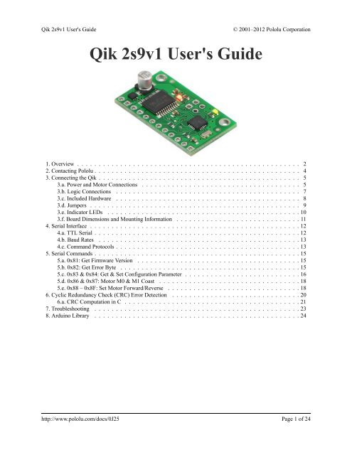
1. Overview<br />
The qik <strong>2s9v1</strong> is <strong>Pololu</strong>’s second-generation dual serial motor controller. The compact board allows any<br />
microcontroller or computer with a serial port (external RS-232 level converter required) or USB-to-serial<br />
adapter [http://www.pololu.com/catalog/product/391] to drive two small, brushed DC motors with full direction <strong>and</strong><br />
speed control. The improvements over the previous generation <strong>and</strong> competing products include:<br />
• high-frequency PWM to eliminate switching-induced motor shaft hum or whine<br />
• a robust, high-speed communication protocol with user-configurable error condition response<br />
• visible LEDs <strong>and</strong> a demo mode to help troubleshoot problematic installations<br />
• reverse power protection on the motor supply (not on the logic supply)<br />
Main Features of the <strong>Qik</strong> <strong>2s9v1</strong><br />
• Simple bidirectional control of two DC brush motors.<br />
• 4.5 V to 13.5 V motor supply range.<br />
• 1 A maximum continuous current per motor (3 A peak).<br />
• 2.7 V to 5.5 V logic supply range.<br />
• Logic-level, non-inverted, two-way serial control for easy connection to microcontrollers or robot<br />
controllers.<br />
• Optional automatic baud rate detection from 1200 bps to 38.4 kbps;<br />
• Two on-board indicator LEDs (status/heartbeat <strong>and</strong> serial error indicator) for debugging <strong>and</strong> feedback.<br />
• Error output to make it easier for the main controller to recover from a serial error condition.<br />
• Jumper-enabled demo mode allowing initial testing without any programming.<br />
• Optional CRC error detection eliminates serial errors caused by noise or software faults.<br />
• Optional motor shutdown on serial error or timeout for additional safety.<br />
Specifications<br />
Motor channels: 2<br />
Motor supply voltage:<br />
Continuous output current per channel:<br />
Peak output current per channel:<br />
Auto-detect baud rate range:<br />
Fixed baud rate:<br />
Available PWM frequencies:<br />
Logic supply voltage:<br />
Reverse voltage protection?:<br />
Motor driver:<br />
Important safety warning<br />
4.5 – 13.5 V<br />
1 A<br />
3 A<br />
1200 – 38400 bps<br />
38400 bps<br />
31.5 kHz, 15.7 kHz, 7.8 kHz, 3.9 kHz<br />
2.7 – 5.5 V<br />
Y (on motor supply only)<br />
TB6612FNG<br />
This product is not intended for young children! Younger users should use this product only under adult<br />
supervision. By using this product, you agree not to hold <strong>Pololu</strong> liable for any injury or damage related to<br />
1. Overview Page 2 of 24
<strong>Qik</strong> <strong>2s9v1</strong> <strong>User's</strong> <strong>Guide</strong><br />
© 2001–2012 <strong>Pololu</strong> Corporation<br />
the use or to the performance of this product. This product is not designed for, <strong>and</strong> should not be used in,<br />
applications where the malfunction of the product could cause injury or damage. Please take note of these<br />
additional precautions:<br />
• This product contains lead, so follow appropriate h<strong>and</strong>ling procedures, such as not licking the product <strong>and</strong><br />
washing h<strong>and</strong>s after h<strong>and</strong>ling.<br />
• Since the PCB <strong>and</strong> its components are exposed, take st<strong>and</strong>ard precautions to protect this product from<br />
ESD (electrostatic discharge), which could damage the on-board electronics. When h<strong>and</strong>ing this product to<br />
another person, first touch their h<strong>and</strong> with your h<strong>and</strong> to equalize any charge imbalance between you so that<br />
you don’t discharge through the electronics as the exchange is made.<br />
• Review the instructions carefully before making any electrical connections, <strong>and</strong> do all wiring while the<br />
power is turned off. Incorrect or reversed wiring could cause an electrical short or unpredictable behavior<br />
that damages this product <strong>and</strong> the devices it is connected to.<br />
• This product is designed to be connected to motors, which should be operated safely. Wear safety glasses,<br />
gloves, or other protective equipment as appropriate, <strong>and</strong> avoid dangerous situations such as motors spinning<br />
out of control by designing appropriate safeguards <strong>and</strong> limits into your projects.<br />
1. Overview Page 3 of 24
<strong>Qik</strong> <strong>2s9v1</strong> <strong>User's</strong> <strong>Guide</strong><br />
© 2001–2012 <strong>Pololu</strong> Corporation<br />
2. Contacting <strong>Pololu</strong><br />
You can check the qik <strong>2s9v1</strong> dual serial motor controller page [http://www.pololu.com/catalog/product/1110] for<br />
additional information. We would be delighted to hear from you about any of your projects <strong>and</strong> about your<br />
experience with the qik motor controller. You can contact us [http://www.pololu.com/contact] directly or post on our<br />
forum [http://forum.pololu.com/]. Tell us what we did well, what we could improve, what you would like to see in<br />
the future, or anything else you would like to say!<br />
2. Contacting <strong>Pololu</strong> Page 4 of 24
<strong>Qik</strong> <strong>2s9v1</strong> <strong>User's</strong> <strong>Guide</strong><br />
© 2001–2012 <strong>Pololu</strong> Corporation<br />
3. Connecting the <strong>Qik</strong><br />
Connecting to the qik can be as simple as hooking up logic <strong>and</strong> motor power, your motors, <strong>and</strong> RX. Many<br />
applications can leave the jumpers off <strong>and</strong> the remaining logic connections—TX, ERR, <strong>and</strong><br />
RESET—disconnected.<br />
The qik connections are shown above, <strong>and</strong> most of the pins are labeled on the back side of the motor controller.<br />
All square pads are ground.<br />
3.a. Power <strong>and</strong> Motor Connections<br />
3. Connecting the <strong>Qik</strong> Page 5 of 24
<strong>Qik</strong> <strong>2s9v1</strong> <strong>User's</strong> <strong>Guide</strong><br />
© 2001–2012 <strong>Pololu</strong> Corporation<br />
The qik motor controller takes two power inputs: motor power supplied via the VMOT <strong>and</strong> GND pins at the<br />
bottom of the board <strong>and</strong> logic power supplied via the VCC <strong>and</strong> GND pins at the top of the board.<br />
Motors <strong>and</strong> Motor Power<br />
The qik can independently drive up to two bidirectional brushed DC motors, referred to as M0 <strong>and</strong> M1. The<br />
two terminals of each motor should be connected to the qik as shown above. Variable speed is achieved with<br />
7-bit or 8-bit pulse width modulated (PWM) outputs at a frequency of 31.5 kHz, 15.7 kHz, 7.8 kHz, or 3.8 kHz.<br />
The highest achievable frequency of 31.5 kHz is ultrasonic, which can result in quieter motor control. Lower<br />
frequencies might make the motors louder, but they can decrease power losses due to switching <strong>and</strong> affect the<br />
relationship between PWM duty cycle <strong>and</strong> motor RPM. The resolution <strong>and</strong> frequency can be set via the qik’s<br />
PWM configuration parameter (see Section 5.c).<br />
The motor direction convention used in this document is that “forward” corresponds to grounding the - pin while<br />
PWMing the + pin between V MOT <strong>and</strong> ground. “Reverse” is the same as forward but with the outputs flipped: + is<br />
held at ground while - is PWMed between V MOT <strong>and</strong> ground. As a result, the motor is rapidly alternating between<br />
drive <strong>and</strong> brake when the direction is “forward” or “reverse”. Variable speed control is achieved by varying the<br />
fraction of the cycle that the motor outputs are driving. Full speed arises when the motor outputs are driving 100%<br />
of the time (one motor output is held at V MOT <strong>and</strong> the other at ground), <strong>and</strong> full braking arises when the motor<br />
outputs are driving 0% of the time (both outputs are held at ground). See Section 5.e for more information on the<br />
motor comm<strong>and</strong>s.<br />
In addition to forward <strong>and</strong> reverse, the qik <strong>2s9v1</strong> can set its motors to “coast” (i.e. the motor shafts will rotate<br />
freely) mode by configuring the motor driver outputs as high-impedance. See Section 5.d for more information.<br />
The motor voltage must be between 4.5 <strong>and</strong> 13.5 V, <strong>and</strong> your motor power source must be capable of supplying<br />
the current your motors will draw. The qik <strong>2s9v1</strong> motor controller uses the TB6612FNG dual motor driver, which<br />
is capable of supplying a continuous 1 A per motor channel, with a peak output of 3 A per channel. Continuous<br />
performance is a function of how well you can keep the motor driver cool; addition of a heat sink or increased<br />
air flow over the board can allow the driver to output higher currents without overheating. The driver has thermal<br />
protection that causes it to shut down when it detects that it is overheating, but it is not a good idea to rely upon<br />
this thermal protection to prevent damage to the unit that can be caused by using it out of spec.<br />
Logic Power<br />
The logic voltage must be between 2.7 <strong>and</strong> 5.5 V <strong>and</strong> must be capable of supplying more than 15 mA (the logic<br />
draws less current at lower voltages <strong>and</strong> when the LEDs are off). Voltages that fall below 2.7 V trigger a brownout<br />
<strong>and</strong> cause the device to reset. Note that the voltage on the qik’s serial input must not exceed Vcc.<br />
While it is possible to use the same power source for both your motors <strong>and</strong> logic, we do not recommend this.<br />
Motors typically add noise to the motor power rail, <strong>and</strong> this noise can negatively impact the functioning of the<br />
device if it is introduced to the logic power rail. If you want to use the same power source for both motors <strong>and</strong><br />
logic, you should decouple the two by using large capacitors <strong>and</strong>/or a regulator. Even if you use separate power<br />
supplies for your motors <strong>and</strong> logic, you should take whatever steps you can to limit electrical noise from your<br />
motors. For example, solder 0.1 uF capacitors across your motor terminals (as shown in the diagram above);<br />
using three capacitors per motor (one across the terminals <strong>and</strong> one from each terminal to the motor can) results<br />
in maximum noise suppression. You can further decrease motor noise by keeping your motor leads as short as<br />
possible <strong>and</strong> twisting the motor leads around each other in a helix.<br />
3. Connecting the <strong>Qik</strong> Page 6 of 24
<strong>Qik</strong> <strong>2s9v1</strong> <strong>User's</strong> <strong>Guide</strong><br />
© 2001–2012 <strong>Pololu</strong> Corporation<br />
Note: Even if your motor <strong>and</strong> logic power sources share a common ground, make sure you connect<br />
your motor power supply’s ground to the GND pin just above the VMOT pin. This ground pin is<br />
designed to h<strong>and</strong>le the higher currents that your motors will draw; the ground pin above the VCC<br />
pin is not intended for high currents.<br />
3.b. Logic Connections<br />
Serial Lines<br />
The qik requires a logic-level (0 – Vcc), non-inverted serial input connected to its serial receive line, RX, <strong>and</strong> it<br />
can h<strong>and</strong>le baud rates from 1200 – 38,400 bps. This type of serial is often referred to as TTL <strong>and</strong> is an interface<br />
method commonly used by microcontrollers. The voltage on this pin should not exceed the supplied logic power<br />
voltage, Vcc. The qik provides logic-level, non-inverted serial output on its serial transmit line, TX, in response<br />
to comm<strong>and</strong>s that request information. Information requests always result in the transmission of a single byte per<br />
request. If you aren’t interested in receiving feedback from the qik, you can leave this line disconnected.<br />
Note that these lines are not compatible with RS-232 serial, which is inverted <strong>and</strong> uses voltages that would be out<br />
of spec (e.g. -12V to 12V). To connect the qik to an RS-232 port, you must use a converter such as our 23201a<br />
serial adapter [http://www.pololu.com/catalog/product/126], or a level shifter <strong>and</strong> inverter.<br />
Reset<br />
The reset line, RST, is an active-low input, which means that it resets the qik when driven low. This pin is<br />
internally pulled to Vcc, so many applications can leave this pin disconnected.<br />
Error<br />
The error line, ERR, is an output that is connected to the red error LED <strong>and</strong> drives high (Vcc) in response to an<br />
error (which in turn lights the LED). Once an error occurs, the pin outputs high until a serial comm<strong>and</strong> is issued to<br />
read the error byte, at which point the pin goes to a high-impedance state that is pulled low through the LED. This<br />
allows you to connect the error lines of multiple qiks to the same digital input. Please note, however, that doing<br />
this will cause the error LEDs of all connected qiks to turn on whenever one qik experiences an error; the ERR<br />
output of the qik experiencing the error will drive the LEDs of any other qiks it is connected to, even though they<br />
are not experiencing error conditions themselves. For more information on the possible error conditions, please<br />
see Section 5.b. If you don’t care about error detection, you can leave this pin disconnected.<br />
3. Connecting the <strong>Qik</strong> Page 7 of 24
<strong>Qik</strong> <strong>2s9v1</strong> <strong>User's</strong> <strong>Guide</strong><br />
© 2001–2012 <strong>Pololu</strong> Corporation<br />
3.c. Included Hardware<br />
The qik ships with a 16×1 straight 0.100" male header strip [http://www.pololu.com/catalog/product/965], a 12×1<br />
right angle 0.100" male header strip [http://www.pololu.com/catalog/product/967], <strong>and</strong> two red shorting blocks<br />
[http://www.pololu.com/catalog/product/971]. This hardware gives you several options when it comes to making<br />
connections to your qik.<br />
For the most compact installation, you can solder wires directly to the qik pins themselves <strong>and</strong> skip using the<br />
included hardware. For less permanent connections, you can break the 16×1 straight header strip into a 12×1<br />
piece <strong>and</strong> two 2×1 pieces. You can optionally solder the 2×1 pieces into the jumper pins, <strong>and</strong> you can solder the<br />
12×1 header strip of your choice into the qik control pins. You can then make your own cables that have female<br />
headers [http://www.pololu.com/catalog/category/50] on them <strong>and</strong> plug these onto the male headers on your qik, or you<br />
can simply plug your qik into a breadboard. Using the right angle header allows for a compact profile or for<br />
vertical mounting into a breadboard; using the straight header allows for breadboarding as shown in the picture<br />
below.<br />
3. Connecting the <strong>Qik</strong> Page 8 of 24
<strong>Qik</strong> <strong>2s9v1</strong> <strong>User's</strong> <strong>Guide</strong><br />
© 2001–2012 <strong>Pololu</strong> Corporation<br />
3.d. Jumpers<br />
The qik jumpers allow you to easily alter the behavior of the device. These jumpers can be left off for most<br />
applications. If you use a jumper, it must be in place when the unit first starts up; changing the jumpers while<br />
the unit is running does not take effect until the qik is reset or power is cycled. The only exception to this is the<br />
removal of the demo mode jumper while the qik is in demo mode, which takes the qik out of demo mode.<br />
Fixed-Baud Mode<br />
The jumper labeled A on the bottom of the qik (i.e. the one closest to the edge of the board) sets the qik to<br />
fixed-baud mode when the shorting block is in place. When the shorting block is absent, the qik is auto-detect<br />
mode <strong>and</strong> determines the baud rate automatically when it receives the first 0xAA (170) byte. If you have a noisy<br />
serial connection or find that the automatic baud detection is not working well for your application, you can use a<br />
shorting block or some other jumper to ground pin A (the circular pin right next to the “A” silkscreen label). This<br />
fixes the qik’s baud rate at 38,400 bps, <strong>and</strong> the qik skips the automatic baud detection phase that normally occurs<br />
on start-up.<br />
Enable-CRC Mode<br />
The jumper labeled B on the bottom of the qik enables cyclic redundancy check (CRC) mode when the shorting<br />
block is in place. This allows you to increase the robustness of your qik connection through the addition of a CRC<br />
error-checking byte to the end of the comm<strong>and</strong> packets you send to the qik. The default behavior of the qik is to<br />
simply respond to a comm<strong>and</strong> packet once it receives the last byte. Grounding pin CRC (the circular pad right<br />
next to the “CRC” silkscreen label) causes the qik to expect an additional CRC byte at the end of every comm<strong>and</strong><br />
packet. The CRC byte is the result of a CRC-7 computation on the entire comm<strong>and</strong> packet, as described in Section<br />
6. If this byte does not match the expected CRC, the qik ignores the comm<strong>and</strong> <strong>and</strong> uses the ERR pin to announce<br />
a CRC error.<br />
3. Connecting the <strong>Qik</strong> Page 9 of 24
<strong>Qik</strong> <strong>2s9v1</strong> <strong>User's</strong> <strong>Guide</strong><br />
© 2001–2012 <strong>Pololu</strong> Corporation<br />
Demo Mode<br />
If you short pin A to pin B (the circular pads right next to the silkscreen labels) <strong>and</strong> reset the qik, it enters demo<br />
mode <strong>and</strong> remains in demo mode for as long as the short is maintained. Demo mode gives you an easy way to test<br />
your qik <strong>and</strong> troubleshoot your application for potential problems. In demo mode, the qik smoothly ramps motor<br />
M0 from stopped to full-speed forward to full-speed reverse to stopped again over a few seconds. It then does the<br />
same for motor M1. The red (error) LED is on while motor M0 is active <strong>and</strong> off while motor M1 is active. The<br />
green (status) LED is on while the active motor is driving forward <strong>and</strong> off while the active motor is driving in<br />
reverse.<br />
Demo mode can help you determine before you’ve even written any code if you have an issue with your power<br />
supply, such as insufficient ability to supply the current your motors are drawing or interference from motor noise.<br />
While in demo mode, any serial data that is received by the qik on the RX line is echoed on the TX line, giving<br />
you an easy way to test your serial connection.<br />
3.e. Indicator LEDs<br />
LED Overview<br />
The qik has two LEDs that are used to provide feedback about its state of operation:<br />
• Status LED (green): This green LED provides a heartbeat to let you know that your qik is alive <strong>and</strong> what<br />
state the qik is in, <strong>and</strong> it also acts as a serial activity indicator.<br />
• Error LED (red): This red LED is tied to the ERR output pin <strong>and</strong> lights when the ERR pin drives high in<br />
response to an error. Once an error occurs, the LED remains lit until a serial comm<strong>and</strong> is issued to read the<br />
error byte, at which point the LED turns off. For more information on the possible error conditions, please<br />
see Section 5.b.<br />
Automatic Baud Detection Phase<br />
When the qik first starts up in automatic baud detection mode, it enters a phase in which it is waiting to receive the<br />
byte 0xAA (170 in decimal) at a baud rate that is within the range of 1200 bps to 38,400 bps. If the serial receive<br />
line, RX, is pulled high, as is expected for an idle TTL serial line <strong>and</strong> the default state of an unconnected RX, the<br />
green status LED flashes on <strong>and</strong> off evenly every 0.4 s. If the serial receive line is held low, this is indicative of a<br />
bad serial connection <strong>and</strong> the red error flashes on <strong>and</strong> off evenly every 0.4 s (with the green status LED off). Once<br />
the baud is detected, this phase ends <strong>and</strong> the qik proceeds to normal operation.<br />
Firmware version 2 only: If a serial byte other than 0xAA is received in this mode, or if 0xAA is transmitted<br />
at an invalid baud rate, the red error LED turns on <strong>and</strong> stays on until the automatic baud detection phase ends.<br />
This gives you feedback that the baud has not yet successfully been set <strong>and</strong> the controller is still in the automatic<br />
detection phase. Firmware version 1 flashes the red LED very briefly if a serial byte other than 0xAA is received<br />
in this mode, which can make it difficult to tell that the qik detected any serial activity.<br />
Normal Operation<br />
In normal operation, the green status LED very briefly flashes a heartbeat every two seconds. If any serial activity<br />
is detected, the green LED turns on until the next heartbeat turns it off. If a serial error occurs, the red LED turns<br />
on <strong>and</strong> remains on until you issue a get-error comm<strong>and</strong> (see Section 5.b).<br />
Demo Mode<br />
In demo mode, the LEDs will cycle through the pattern:<br />
1. red <strong>and</strong> green ON<br />
3. Connecting the <strong>Qik</strong> Page 10 of 24
<strong>Qik</strong> <strong>2s9v1</strong> <strong>User's</strong> <strong>Guide</strong><br />
© 2001–2012 <strong>Pololu</strong> Corporation<br />
2. red ON <strong>and</strong> green OFF<br />
3. red OFF <strong>and</strong> green ON<br />
4. red <strong>and</strong> green OFF<br />
This cycle takes several seconds, <strong>and</strong> each of the four LED states corresponds to a different output state of the<br />
qik’s motor ports. When the red error LED is on, motor M0 is active, <strong>and</strong> when the red error LED is off, motor<br />
M1 is active. When the green status LED is on, the active motor is moving forward, <strong>and</strong> when the green status<br />
LED is off, the active motor is moving in reverse.<br />
3.f. Board Dimensions <strong>and</strong> Mounting Information<br />
The qik <strong>2s9v1</strong> measures 0.7" x 1.2" x 0.28" (17.8 x 30.5 x 7.1 mm) <strong>and</strong> weighs 0.07 oz (2.0 g) without the header<br />
pins installed. It has two mounting holes, one in each top corner. The holes have a diameter of 0.086" <strong>and</strong> are<br />
designed for #2 or M2 screws.<br />
3. Connecting the <strong>Qik</strong> Page 11 of 24
<strong>Qik</strong> <strong>2s9v1</strong> <strong>User's</strong> <strong>Guide</strong><br />
© 2001–2012 <strong>Pololu</strong> Corporation<br />
4. Serial Interface<br />
You can use the serial interface for three general purposes: querying the qik for information, setting its<br />
configuration parameters, <strong>and</strong> sending it motor comm<strong>and</strong>s. Motor comm<strong>and</strong>s are strictly one-way; all other<br />
comm<strong>and</strong>s result in the qik’s responding with a single byte that either represents information that has been<br />
requested or feedback on the effect of the issued comm<strong>and</strong>.<br />
4.a. TTL Serial<br />
The qik requires a logic-level (0 – Vcc, or “TTL”), non-inverted serial input connected to its serial receive line<br />
RX. The serial interface is asynchronous, meaning that the sender <strong>and</strong> receiver each independently time the serial<br />
bits; asynchronous serial is available in computer serial ports (though at non-TTL levels) <strong>and</strong> as hardware modules<br />
called “UARTs” on many microcontrollers. Asynchronous serial output can also be “bit-banged” by a st<strong>and</strong>ard<br />
digital output line under software control. The data format is 8 data bits, one stop bit, with no parity. The diagram<br />
below depicts a typical asynchronous, non-inverted TTL serial byte.<br />
A non-inverted TTL serial line has a default (non-active) state of high. A transmitted byte begins with a single<br />
low “start bit”, followed by the bits of the byte, least-significant bit (LSB) first. Logical ones are transmitted as<br />
high (Vcc) <strong>and</strong> logical zeros are transmitted as low (0 V), which is why this format is referred to as “non-inverted”<br />
serial. The byte is terminated by a “stop bit”, which is the line going high for at least one bit time. Because each<br />
byte also requires start <strong>and</strong> stop bits, each byte takes 10 bit times to transmit, so the fastest possible data rate<br />
in bytes per second is the baud rate divided by ten. At the maximum baud rate of 38,400 bits per second, the<br />
maximum realizable data rate, with a start bit coming immediately after the preceding byte’s stop bit, is 3,840<br />
bytes per second.<br />
The voltage on the RX pin should not exceed Vcc. The qik will provide logic-level serial output on its serial<br />
transmit line TX in response to comm<strong>and</strong>s that request information. Information requests aways result in the<br />
transmission of a single byte per request. If you aren’t interested in receiving feedback from the qik, you can leave<br />
this line disconnected.<br />
4. Serial Interface Page 12 of 24
<strong>Qik</strong> <strong>2s9v1</strong> <strong>User's</strong> <strong>Guide</strong><br />
© 2001–2012 <strong>Pololu</strong> Corporation<br />
Note: These lines are not compatible with RS-232 serial, which is inverted <strong>and</strong> uses voltages that<br />
would be out of spec (e.g. -12V to 12V). To connect the qik to an RS-232 device, you will need<br />
to use a converter such as our 23201a serial adapter [http://www.pololu.com/catalog/product/126], or a<br />
level shifter <strong>and</strong> inverter.<br />
4.b. Baud Rates<br />
The qik can h<strong>and</strong>le baud rates between 1200 <strong>and</strong> 38,400 bps. In its default state, the qik will start up in an<br />
automatic baud detection phase, where it waits for you to send it the byte 0xAA (170). The qik will detect the<br />
baud rate you are using from this byte <strong>and</strong> proceed to the normal operation phase. If you have the fixed-baud<br />
jumper in place, the qik will skip the autodetect phase <strong>and</strong> will instead immediately begin normal operation at a<br />
baud rate of 38,400 bps. Please see Section 3.d for more information.<br />
4.c. Comm<strong>and</strong> Protocols<br />
Once the qik has entered the normal operation phase, you can control it by issuing serial comm<strong>and</strong>s. If your qik<br />
is set to automatically detect the baud, you must first send it the byte 0xAA (170) in order to exit autodetect mode<br />
<strong>and</strong> enter normal operation.<br />
The qik serial comm<strong>and</strong> protocol is fairly simple. Communication is achieved by sending comm<strong>and</strong> packets<br />
consisting of a single comm<strong>and</strong> byte followed by any data bytes that comm<strong>and</strong> requires. Comm<strong>and</strong> bytes always<br />
have their most significant bits set (i.e. range from 128 – 255) while data bytes always have their most significant<br />
bits cleared (i.e. range from 0 – 127). This means that each data byte can only transmit seven bits of information.<br />
One significant improvement over earlier <strong>Pololu</strong> serial controllers is the qik’s error h<strong>and</strong>ling, which allows the<br />
user to specify responses to serial errors (which include bad comm<strong>and</strong>s, incorrectly formatted comm<strong>and</strong>s, or even<br />
hardware-level serial errors). The qik has a configuration parameter that, if set, will shut down the motors if a<br />
serial error occurs, but the qik itself will continue running <strong>and</strong> accepting comm<strong>and</strong>s. This is a safety precaution<br />
taken in case the serial error occurred during a comm<strong>and</strong> that was intended to stop the motors.<br />
The qik responds to two sub-protocols:<br />
Compact Protocol:<br />
This is the simpler <strong>and</strong> more compact of the two protocols; it is the protocol you should use if your qik is the only<br />
device connected to your serial line. The qik compact protocol comm<strong>and</strong> packet is simply:<br />
comm<strong>and</strong> byte (with MSB set), any necessary data bytes<br />
For example, if we want to set motor M1 to full speed forward using the compact protocol, we could send the<br />
following byte sequence:<br />
in hex: 0x8D, 0x7F<br />
in decimal: 141, 127<br />
The byte 0x8D is a comm<strong>and</strong> for M1 forward, <strong>and</strong> the data byte contains the motor speed. Note that every qik<br />
comm<strong>and</strong> byte will start with 0x8_ when using the compact protocol.<br />
4. Serial Interface Page 13 of 24
<strong>Qik</strong> <strong>2s9v1</strong> <strong>User's</strong> <strong>Guide</strong><br />
© 2001–2012 <strong>Pololu</strong> Corporation<br />
<strong>Pololu</strong> Protocol:<br />
This protocol is compatible with the serial protocol used by our other serial motor <strong>and</strong> servo controllers. As such,<br />
you can daisy-chain a qik on a single serial line along with our other serial controllers (including additional qiks)<br />
<strong>and</strong>, using this protocol, send comm<strong>and</strong>s specifically to the desired qik without confusing the other devices on the<br />
line.<br />
The <strong>Pololu</strong> protocol is to transmit 0xAA (170 in decimal) as the first (comm<strong>and</strong>) byte, followed by a devicenumber<br />
data byte. The default device number for the qik is 9, but this is a configuration parameter you can change.<br />
Any qik on the line whose device number matches the specified device number will accept the comm<strong>and</strong> that<br />
follows; all other <strong>Pololu</strong> devices will ignore the comm<strong>and</strong>. The remaining bytes in the comm<strong>and</strong> packet are the<br />
same as the compact protocol comm<strong>and</strong> packet you would send, with one key difference: the compact protocol<br />
comm<strong>and</strong> byte is now a data byte for the comm<strong>and</strong> 0xAA <strong>and</strong> hence must have its most significant bit cleared.<br />
Therefore, the comm<strong>and</strong> packet is:<br />
0xAA, device # byte, comm<strong>and</strong> byte with MSB cleared, any necessary data bytes<br />
For example, if we want to set motor M1 to full speed forward for a qik with device number 9, we could send the<br />
following byte sequence:<br />
in hex: 0xAA, 0x09, 0x0D, 0x7F<br />
in decimal: 170, 9, 13, 127<br />
Note that 0x0D is the comm<strong>and</strong> 0x8D with its most significant bit cleared. Since all compact-protocol comm<strong>and</strong><br />
bytes start with 0x8n, these bytes will all turn into data bytes 0x0n.<br />
The qik will respond to both the <strong>Pololu</strong> <strong>and</strong> Compact protocols on the fly; you do not need to use a jumper or<br />
configuration parameter to identify which protocol you will be using.<br />
Procedure for Daisy-Chaining<br />
Daisy-chaining multiple qiks together on the same serial line is simple. Individually assign each qik a different<br />
device ID using the set configuration parameter comm<strong>and</strong> (see Section 5.c), <strong>and</strong> then connect your TTL serial<br />
transmit line to each qik’s RX line. If you wish, you can connect all of the qiks’ ERR lines to a single input on your<br />
controlling module. When you issue your first <strong>Pololu</strong>-protocol comm<strong>and</strong>, the qiks will all automatically detect the<br />
baud from the initial 0xAA byte.<br />
Connecting multiple serial outputs to one serial input is more complicated. Each device will only transmit when<br />
requested, so if each unit is addressed separately, multiple units will not transmit simultaneously. However, the<br />
outputs are driven, so they cannot simply be wired together. Instead, you can use an AND gate (since the idle state<br />
is high).<br />
If you want to daisy-chain a qik with other <strong>Pololu</strong> devices that use 0x80 as an initial comm<strong>and</strong> byte, the<br />
procedure becomes slightly more complicated. You should first transmit the byte 0x80 so that these devices can<br />
automatically detect the baud rate, <strong>and</strong> only then should you send the byte 0xAA so that the qik can detect the<br />
baud rate. Once all devices have detected the baud rate, <strong>Pololu</strong> devices that expect a leading comm<strong>and</strong> byte of<br />
0x80 should ignore comm<strong>and</strong> packets that start with 0xAA <strong>and</strong> qiks will ignore comm<strong>and</strong> packets that start with<br />
0x80.<br />
4. Serial Interface Page 14 of 24
<strong>Qik</strong> <strong>2s9v1</strong> <strong>User's</strong> <strong>Guide</strong><br />
© 2001–2012 <strong>Pololu</strong> Corporation<br />
5. Serial Comm<strong>and</strong>s<br />
5.a. 0x81: Get Firmware Version<br />
Compact protocol: 0x81<br />
<strong>Pololu</strong> protocol: 0xAA, device ID, 0x01<br />
This comm<strong>and</strong> returns the a single ASCII byte that represents the version of the firmware running on the qik. All<br />
qiks produced so far have firmware version ‘1’ or ‘2’.<br />
Firmware version 2 makes a slight change to the LED feedback used during the automatic baud detection phase. If<br />
a serial byte other than 0xAA is received in this phase, or if 0xAA is transmitted at an invalid baud rate, firmware<br />
version 2 turns the red error LED on <strong>and</strong> keeps it on until the automatic baud detection phase ends. Firmware<br />
version 1 flashes the red LED very briefly if a serial byte other than 0xAA is received in this mode, which can<br />
make it difficult to tell that the qik detected any serial activity.<br />
5.b. 0x82: Get Error Byte<br />
Compact protocol: 0x82<br />
<strong>Pololu</strong> protocol: 0xAA, device ID, 0x02<br />
The qik maintains an error byte, the bits of which, when set, reflect various errors that have been detected since<br />
the byte was last read using this comm<strong>and</strong>. If we call the least-significant bit 0, the bits of the error byte are as<br />
follows:<br />
• bits 0 – 2: unused<br />
• bit 3: Data Overrun Error<br />
A hardware-level error that occurs when serial data is received while the hardware serial receive buffer is<br />
full. This error should not occur during normal operation.<br />
• bit 4: Frame Error<br />
A hardware-level error that occurs when a byte’s stop bit is not detected at the expected place. This error can<br />
occur if you are communicating at a baud rate that differs from the qik’s baud rate.<br />
• bit 5: CRC Error<br />
This error occurs when the qik is running in CRC-enabled mode (i.e. the CRC-enable jumper is in place) <strong>and</strong><br />
the cyclic redundancy check (CRC) byte added to the end of the comm<strong>and</strong> packet does not match what the<br />
qik has computed as that packet’s CRC. In such a case, the qik will ignore the comm<strong>and</strong> packet <strong>and</strong> generate<br />
a CRC error. See Section 6 for more information on cyclic redundancy checking.<br />
• bit 6: Format Error<br />
This error occurs when the qik receives an incorrectly formatted or nonsensical comm<strong>and</strong> packet. For<br />
example, if the comm<strong>and</strong> byte does not match a known comm<strong>and</strong>, data bytes are outside of the allowed range<br />
for their particular comm<strong>and</strong>, or an unfinished comm<strong>and</strong> packet is interrupted by another comm<strong>and</strong> packet,<br />
a format error will be generated.<br />
• bit 7: Timeout<br />
It is possible to use a configuration parameter to enable the qik’s serial timeout feature (see Section 5.c).<br />
When enabled, the qik will generate a timeout error if the timeout period set by the configuration parameter<br />
elapses. The timeout timer is reset every time a valid comm<strong>and</strong> packet is received.<br />
An error will cause the red LED to light <strong>and</strong> the ERR pin to drive high until this comm<strong>and</strong> is called. Calling this<br />
comm<strong>and</strong> will clear the error byte, turn the red LED off, <strong>and</strong> set the ERR pin as high-impedance (causing it to be<br />
5. Serial Comm<strong>and</strong>s Page 15 of 24
<strong>Qik</strong> <strong>2s9v1</strong> <strong>User's</strong> <strong>Guide</strong><br />
© 2001–2012 <strong>Pololu</strong> Corporation<br />
pulled low through the LED). If shutdown-on-error configuration parameter is set to 1, motors M0 <strong>and</strong> M1 will<br />
be stopped as a safety precaution when any of these errors occurs (see Section 5.c).<br />
5.c. 0x83 & 0x84: Get & Set Configuration Parameter<br />
The qik has four configuration parameters that are saved in non-volatile memory, <strong>and</strong> uses comm<strong>and</strong>s 0x83 <strong>and</strong><br />
0x84 to read <strong>and</strong> write these parameter values, respectively. The parameters are numbered as follows:<br />
Configuration Parameters<br />
• 0: Device ID<br />
This parameter determines which device ID the unit will respond to when the <strong>Pololu</strong> protocol is used. It has<br />
a default value of 9 (0x09 in hex) <strong>and</strong> can be set to any value from 0 – 127. When setting this parameter, you<br />
should only have one qik on your serial line at a time.<br />
• 1: PWM Parameter<br />
This parameter determines frequency <strong>and</strong> resolution of the pulse width modulation (PWM) signal used to<br />
control motor speed. Note that setting this parameter while the motors are running causes them to stop.<br />
The least significant bit (bit 0) selects for 7-bit resolution when cleared (i.e. full motor speed is 127) <strong>and</strong> 8-bit<br />
resolution when set (i.e. full motor speed is 255). A PWM with 7-bit resolution has twice the frequency of<br />
one with 8-bit resolution.<br />
Bit 1 of this parameter selects for high-frequency mode when cleared <strong>and</strong> low-frequency mode when set.<br />
Using high-frequency mode puts the PWM frequency outside the range of human hearing if you are also in<br />
7-bit mode (or very close to it if you are in 8-bit mode), which can help you decrease motor noise. Using low<br />
frequency mode has the benefit of decreasing power losses due to switching.<br />
The default value for this parameter is 0 (high-frequency 7-bit mode, resulting in a PWM frequency of<br />
31.5 kHz).<br />
Valid values for this parameter are:<br />
◦ 0 = high-frequency, 7-bit mode (PWM frequency of 31.5 kHz, which is ultrasonic)<br />
◦ 1 = high-frequency, 8-bit mode (PWM frequency of 15.7 kHz)<br />
◦ 2 = low-frequency, 7-bit mode (PWM frequency of 7.8 kHz)<br />
◦ 3 = low-frequency, 8-bit mode (PWM frequency of 3.9 kHz)<br />
• 2: Shutdown Motors on Error<br />
When this parameter has a value of 1, both motors M0 <strong>and</strong> M1 are stopped as a safety precaution whenever<br />
an error occurs; otherwise, if this parameter has a value of 0, errors will not affect the motors. For more<br />
information on the various types of errors that can occur, see Section 5.b. This parameter has a default value<br />
of 1 (shut down the motors on any error) <strong>and</strong> valid values for this parameter are 0 or 1.<br />
• 3: Serial Timeout<br />
When this parameter has a value of 0, the serial timeout feature is inactive. Otherwise, the value of this<br />
parameter controls how much time can elapse between receptions of valid comm<strong>and</strong> packets before a serial<br />
timeout error is generated. This can be used as a general safety feature to allow the qik to identify when<br />
communication with the controlling device is lost <strong>and</strong> shut down the motors as a result (assuming the<br />
shutdown motors on error parameter set to a value of 1).<br />
The timeout duration is specified in increments of 262 ms (approximately a quarter of a second) <strong>and</strong> is<br />
calculated as the lower four bits (which are interpreted as a number from 0 – 15) times two to the upper three<br />
5. Serial Comm<strong>and</strong>s Page 16 of 24
<strong>Qik</strong> <strong>2s9v1</strong> <strong>User's</strong> <strong>Guide</strong><br />
© 2001–2012 <strong>Pololu</strong> Corporation<br />
bits (which are interpreted as a number from 0 – 7). If the lower four bits are called x <strong>and</strong> the upper three bits<br />
are called y, the equation for the length of the timeout duration would be:<br />
timeout = 0.262 seconds * x * 2 y<br />
For example, if the timeout parameter is set as 0x5E (01011110 in binary), we have that x = 1110 (binary) =<br />
14 (decimal) <strong>and</strong> y = 101 (binary) = 5 (decimal), which results in a timeout duration of<br />
0.262s * 14 * 2 5 = 117 seconds.<br />
The maximum timeout duration (arising from a parameter value of 0x7F, or 127 in decimal) is 8.32 minutes<br />
<strong>and</strong> the minimum timeout duration (arising from a parameter value of 1) is 262 ms.<br />
This parameter has a default value of 0 (serial timeout disabled) <strong>and</strong> can be set to any value from 0 – 127.<br />
Comm<strong>and</strong> 0x83: Get Configuration Parameter<br />
Compact protocol: 0x83, parameter number<br />
<strong>Pololu</strong> protocol: 0xAA, device ID, 0x03, parameter number<br />
This comm<strong>and</strong> lets you request the current value of any of the four configuration parameters detailed above. This<br />
comm<strong>and</strong> will cause the qik to transmit a single byte that represents the requested parameter value. If you request<br />
an invalid parameter (i.e. if parameter number ≥ 4), the value transmitted by the qik should be 0xFF (255 in<br />
decimal) <strong>and</strong> a format error will be generated.<br />
Comm<strong>and</strong> 0x84: Set Configuration Parameter<br />
Compact protocol: 0x84, parameter number, parameter value, 0x55, 0x2A<br />
<strong>Pololu</strong> protocol: 0xAA, device ID, 0x04, parameter number, parameter value, 0x55, 0x2A<br />
This comm<strong>and</strong> lets you set the value of any of the four configuration parameters detailed above. The final two<br />
bytes of the comm<strong>and</strong> packets are format bytes that make it more difficult for this comm<strong>and</strong> to be unintentionally<br />
or accidentally sent, as might result from a noisy serial connection or buggy code. If either of the format bytes<br />
differs from the expected value, the comm<strong>and</strong> is ignored <strong>and</strong> a format error is generated.<br />
It takes the qik approximately 4 ms to finish processing this comm<strong>and</strong>, at which point the qik will transmit a single<br />
return byte that contains information about whether the process was successful. You should not send comm<strong>and</strong>s<br />
to the qik until you have received this return byte, or until at least 4 ms have elapsed. The return byte can have the<br />
following values:<br />
• 0: Comm<strong>and</strong> OK (success)<br />
• 1: Bad Parameter (failure due to invalid parameter number)<br />
• 2: Bad value (failure due to invalid parameter value for the specified parameter number)<br />
Failure will result in a format error.<br />
Once you have set the value of a configuration parameter, that value will be saved even if the unit is unplugged or<br />
reset.<br />
5. Serial Comm<strong>and</strong>s Page 17 of 24
<strong>Qik</strong> <strong>2s9v1</strong> <strong>User's</strong> <strong>Guide</strong><br />
© 2001–2012 <strong>Pololu</strong> Corporation<br />
5.d. 0x86 & 0x87: Motor M0 & M1 Coast<br />
Comm<strong>and</strong> 0x86: Motor M0 Coast<br />
Compact protocol: 0x86<br />
<strong>Pololu</strong> protocol: 0xAA, device ID, 0x06<br />
Comm<strong>and</strong> 0x87: Motor M1 Coast<br />
Compact protocol: 0x87<br />
<strong>Pololu</strong> protocol: 0xAA, device ID, 0x07<br />
These comm<strong>and</strong>s will set the specified motor to coast by setting the motor outputs to high impedance, which lets<br />
the motor turn freely. This is in contrast to setting the motor speed to 0, which sets the motor outputs to ground<br />
<strong>and</strong> acts as a brake, resisting motor rotation.<br />
You can see the effect of this yourself just by using your motor. First, with your motor disconnected from<br />
anything, try rotating the output shaft <strong>and</strong> note how easily it turns. Then, short the two motor leads together <strong>and</strong><br />
try rotating the output shaft again. You should notice significantly more resistance while the leads are shorted<br />
together. The motor-coast comm<strong>and</strong> is equivalent to disconnecting your motor <strong>and</strong> letting it turn freely while<br />
setting the motor speed to zero is equivalent to shorting the motor leads together.<br />
5.e. 0x88 - 0x8F: Set Motor Forward/Reverse<br />
The qik can independently control two bidirectional brushed DC motors, driving each either forward or reverse<br />
with either 7- or 8-bit speed resolution. In 7-bit mode, motor speed ranges from stopped to full speed as the<br />
speed parameter ranges from 0 to 127. In 8-bit mode, motor speed ranges from stopped to full speed as the speed<br />
parameter ranges from 0 – 255. The speed resolution can be controlled by the PWM configuration parameter (see<br />
Section 5.c).<br />
The motor direction convention used in this document is that “forward” corresponds to grounding the – pin while<br />
PWMing the + pin between V MOT <strong>and</strong> ground. “Reverse” corresponds to grounding the + pin while PWMing the<br />
– pin between V MOT <strong>and</strong> ground. Notions of “forward” <strong>and</strong> “reverse” are somewhat arbitrary. See Section 3.a for<br />
information about motor <strong>and</strong> power connections.<br />
Motor M0 Comm<strong>and</strong>s<br />
Comm<strong>and</strong>s 0x88 – 0x8B apply to motor M0. In 8-bit mode, comm<strong>and</strong>s 0x89 <strong>and</strong> 0x8B will set the motor speed<br />
to 128+motor speed; in 7-bit mode, comm<strong>and</strong> 0x89 is identical to comm<strong>and</strong> 0x88 <strong>and</strong> comm<strong>and</strong> 0x8B is identical<br />
to comm<strong>and</strong> 0x8A.<br />
For example, in 8-bit mode, the comm<strong>and</strong> packet 0x88, 0x7F will set motor M0 speed to 127 out of a maximum<br />
of 255, which will result in the motor’s turning at half speed. The comm<strong>and</strong> packet 0x89, 0x7F will set motor M0<br />
speed to 127+128 = 255, which will result in the motor’s turning at full speed. In 7-bit mode, both comm<strong>and</strong>s will<br />
set motor M0 speed to 127 out of a maximum of 127, which will result in the motor’s turning at full speed.<br />
Comm<strong>and</strong> 0x88: Motor M0 Forward<br />
Compact protocol: 0x88, motor speed<br />
<strong>Pololu</strong> protocol: 0xAA, device ID, 0x08, motor speed<br />
Comm<strong>and</strong> 0x89: Motor M0 Forward (speed + 128; used in 8-bit mode)<br />
Compact protocol: 0x89, motor speed<br />
<strong>Pololu</strong> protocol: 0xAA, device ID, 0x09, motor speed<br />
5. Serial Comm<strong>and</strong>s Page 18 of 24
<strong>Qik</strong> <strong>2s9v1</strong> <strong>User's</strong> <strong>Guide</strong><br />
© 2001–2012 <strong>Pololu</strong> Corporation<br />
Comm<strong>and</strong> 0x8A: Motor M0 Reverse<br />
Compact protocol: 0x8A, motor speed<br />
<strong>Pololu</strong> protocol: 0xAA, device ID, 0x0A, motor speed<br />
Comm<strong>and</strong> 0x8B: Motor M0 Reverse (speed + 128; used in 8-bit mode)<br />
Compact protocol: 0x8B, motor speed<br />
<strong>Pololu</strong> protocol: 0xAA, device ID, 0x0B, motor speed<br />
Motor M1 Comm<strong>and</strong>s<br />
Comm<strong>and</strong>s 0x8C – 0x8F apply to motor M1. In 8-bit mode, comm<strong>and</strong>s 0x8D <strong>and</strong> 0x8F will set the motor speed to<br />
128+motor speed; in 7-bit mode, comm<strong>and</strong> 0x8D is identical to comm<strong>and</strong> 0x8C <strong>and</strong> comm<strong>and</strong> 0x8F is identical<br />
to comm<strong>and</strong> 0x8E.<br />
For example, in 8-bit mode, the comm<strong>and</strong> packet 0x8C, 0x7F will set motor M1 speed to 127 out of a maximum<br />
of 255, which will result in the motor’s turning at half speed. The comm<strong>and</strong> packet 0x8D, 0x7F will set motor<br />
M1 speed to 127+128 = 255, which will result in the motor’s turning at full speed. In 7-bit mode, both comm<strong>and</strong>s<br />
will set motor M1 speed to 127 out of a maximum of 127, which will result in the motor’s turning at full speed.<br />
Comm<strong>and</strong> 0x8C: Motor M1 Forward<br />
Compact protocol: 0x8C, motor speed<br />
<strong>Pololu</strong> protocol: 0xAA, device ID, 0x0C, motor speed<br />
Comm<strong>and</strong> 0x8D: Motor M1 Forward (speed + 128; used in 8-bit mode)<br />
Compact protocol: 0x8D, motor speed<br />
<strong>Pololu</strong> protocol: 0xAA, device ID, 0x0D, motor speed<br />
Comm<strong>and</strong> 0x8E: Motor M1 Reverse<br />
Compact protocol: 0x8E, motor speed<br />
<strong>Pololu</strong> protocol: 0xAA, device ID, 0x0E, motor speed<br />
Comm<strong>and</strong> 0x8F: Motor M1 Reverse (speed + 128; used in 8-bit mode)<br />
Compact protocol: 0x8F, motor speed<br />
<strong>Pololu</strong> protocol: 0xAA, device ID, 0x0F, motor speed<br />
5. Serial Comm<strong>and</strong>s Page 19 of 24
<strong>Qik</strong> <strong>2s9v1</strong> <strong>User's</strong> <strong>Guide</strong><br />
© 2001–2012 <strong>Pololu</strong> Corporation<br />
6. Cyclic Redundancy Check (CRC) Error Detection<br />
For certain applications, verifying the integrity of the data you’re sending <strong>and</strong> receiving can be very important.<br />
Because of this, the qik has optional 7-bit cyclic redundancy checking, which is similar to a checksum but more<br />
robust as it can detect some possible errors, such as an extra zero byte, that would not affect a checksum.<br />
When jumper B is in place, cyclic redundancy checking is enabled. In CRC mode, the qik expects an extra byte<br />
to be added onto the end of every comm<strong>and</strong> packet. The lower seven bits of this byte must be the 7-bit CRC for<br />
that packet, or else the qik will set its CRC Error bit in the error byte <strong>and</strong> ignore the comm<strong>and</strong>. The qik does not<br />
append any CRC information to the data it sends back, which always consists of just one byte.<br />
A detailed account of how cyclic redundancy checking works is beyond the scope of this document, but you can<br />
find a wealth of information using Wikipedia [http://en.wikipedia.org/wiki/Cyclic_redundancy_check]. The quick version<br />
is that a CRC computation is basically a carryless long division of a CRC “polynomial” 0x91 into your message<br />
(expressed as a continuous stream of bits), where all you care about is the remainder. The qik uses CRC-7,<br />
which means it uses an 8-bit polynomial (whose most-significant bit, or MSB, must always be 1) <strong>and</strong>, as a result,<br />
produces a 7-bit remainder. This remainder is the lower 7 bits of the CRC byte you tack onto the end of your<br />
comm<strong>and</strong> packets.<br />
The CRC implemented on the qik is the same as on the jrk [http://www.pololu.com/catalog/product/1392]<br />
motor controller but differs from that on the TReX [http://www.pololu.com/catalog/product/777] motor<br />
controller. Instead of being done MSB first, it is LSB first, to match the order in which the bits<br />
are transmitted over the serial line. In st<strong>and</strong>ard binary notation, the number 0x91 is written as<br />
10010001. However, the bits are transmitted in this order: 1, 0, 0, 0, 1, 0, 0, 1, so we will write it<br />
as 10001001 to carry out the computation below.<br />
The CRC-7 algorithm is as follows:<br />
1. Express your 8-bit CRC-7 polynomial <strong>and</strong> message in binary, LSB first. The polynomial 0x91 is written<br />
as 10001001.<br />
2. Add 7 zeros to the end of your message.<br />
3. Write your CRC-7 polynomial underneath the message so that the LSB of your polynomial is directly<br />
below the LSB of your message.<br />
4. If the LSB of your CRC-7 is aligned under a 1, XOR the CRC-7 with the message to get a new message;<br />
if the LSB of your CRC-7 is aligned under a 0, do nothing.<br />
5. Shift your CRC-7 right one bit. If all 8 bits of your CRC-7 polynomial still line up underneath message<br />
bits, go back to step 4.<br />
6. What’s left of your message is now your CRC-7 result (transmit these seven bits as your CRC byte when<br />
talking to the qik with CRC enabled).<br />
If you’ve never encountered CRCs before, this probably sounds a lot more complicated than it really is. The<br />
following example shows that the CRC-7 calculation is not that difficult. For the example, we will use a two-byte<br />
sequence: 0x83, 0x01 (the comm<strong>and</strong> packet to get the PWM configuration parameter byte).<br />
Steps 1 & 2 (write as binary, add 7 zeros to the end of the message):<br />
CRC-7 Polynomial = [1 0 0 0 1 0 0 1]<br />
message = [1 1 0 0 0 0 0 1] [1 0 0 0 0 0 0 0] 0 0 0 0 0 0 0<br />
6. Cyclic Redundancy Check (CRC) Error Detection Page 20 of 24
<strong>Qik</strong> <strong>2s9v1</strong> <strong>User's</strong> <strong>Guide</strong><br />
© 2001–2012 <strong>Pololu</strong> Corporation<br />
Steps 3, 4, & 5:<br />
_______________________________________________<br />
1 0 0 0 1 0 0 1 ) 1 1 0 0 0 0 0 1 1 0 0 0 0 0 0 0 0 0 0 0 0 0 0<br />
XOR 1 0 0 0 1 0 0 1 | | | | | | | | | | | | | | |<br />
--------------- | | | | | | | | | | | | | | |<br />
1 0 0 1 0 0 0 1 | | | | | | | | | | | | | |<br />
shift ----> 1 0 0 0 1 0 0 1 | | | | | | | | | | | | | |<br />
_______________ | | | | | | | | | | | | | |<br />
1 1 0 0 0 0 0 0 | | | | | | | | | | |<br />
1 0 0 0 1 0 0 1 | | | | | | | | | | |<br />
_______________ | | | | | | | | | | |<br />
1 0 0 1 0 0 1 0 | | | | | | | | | |<br />
1 0 0 0 1 0 0 1 | | | | | | | | | |<br />
_______________ | | | | | | | | | |<br />
1 1 0 1 1 0 0 0 | | | | | | |<br />
1 0 0 0 1 0 0 1 | | | | | | |<br />
_______________ | | | | | | |<br />
1 0 1 0 0 0 1 0 | | | | | |<br />
1 0 0 0 1 0 0 1 | | | | | |<br />
_______________ | | | | | |<br />
1 0 1 0 1 1 0 0 | | | |<br />
1 0 0 0 1 0 0 1 | | | |<br />
_______________ | | | |<br />
1 0 0 1 0 1 0 0 | |<br />
1 0 0 0 1 0 0 1 | |<br />
_______________ | |<br />
1 1 1 0 1 0 0 = 0x17<br />
So the full comm<strong>and</strong> packet we would send to retrieve the PWM configuration parameter with CRC enabled is:<br />
0x83, 0x01, 0x17<br />
There are some tricks you can use in your programs to make the CRC calculation much faster. You can find an<br />
example of this Section 6.a.<br />
6.a. CRC Computation in C<br />
The following example program shows how to compute a CRC in the C language. The idea is that the CRC of<br />
every possible byte is stored in a lookup table, so that it can be quickly loaded when computing the CRC of a<br />
longer message. The individual CRC bytes are XORed together with the C operator ^ to get the final CRC of the<br />
message. In the example main() routine, this is applied to generate the CRC byte in the message 0x83, 0x01, that<br />
was used in Section 6.<br />
#include <br />
const unsigned char CRC7_POLY = 0x91;<br />
unsigned char CRCTable[256];<br />
unsigned char GetCRC(unsigned char val)<br />
{<br />
unsigned char j;<br />
for (j = 0; j < 8; j++)<br />
{<br />
if (val & 1)<br />
val ^= CRC7_POLY;<br />
val >>= 1;<br />
}<br />
}<br />
return val;<br />
void GenerateCRCTable()<br />
{<br />
int i, j;<br />
// generate a table value for all 256 possible byte values<br />
for (i = 0; i < 256; i++)<br />
{<br />
CRCTable[i] = GetCRC(i);<br />
}<br />
6. Cyclic Redundancy Check (CRC) Error Detection Page 21 of 24
<strong>Qik</strong> <strong>2s9v1</strong> <strong>User's</strong> <strong>Guide</strong><br />
© 2001–2012 <strong>Pololu</strong> Corporation<br />
}<br />
unsigned char CRC(unsigned char message[], unsigned char length)<br />
{<br />
unsigned char i, crc = 0;<br />
}<br />
for (i = 0; i < length; i++)<br />
crc = CRCTable[crc ^ message[i]];<br />
return crc;<br />
int main()<br />
{<br />
unsigned char message[3] = {0x83, 0x01, 0x00};<br />
int i,j;<br />
GenerateCRCTable();<br />
message[2] = CRC(message,2);<br />
}<br />
for(i=0;ij)%2);<br />
printf(" ");<br />
}<br />
printf("\n");<br />
return 0;<br />
6. Cyclic Redundancy Check (CRC) Error Detection Page 22 of 24
<strong>Qik</strong> <strong>2s9v1</strong> <strong>User's</strong> <strong>Guide</strong><br />
© 2001–2012 <strong>Pololu</strong> Corporation<br />
7. Troubleshooting<br />
The following are some suggestions for ways you can troubleshoot your qik:<br />
• Test for life: With nothing more than logic voltage connected, look for a green LED heartbeat. If you do<br />
not see the green LED flashing, you either lack sufficient logic power (e.g. the voltage is out of range or the<br />
power supply is too noisy) or your qik is damaged. See Section 3.a for more information about logic power<br />
requirements.<br />
• Test your serial connection: Put on the fixed baud jumper (with the CRC jumper is off), connect your<br />
TTL serial control source to the qik’s RX pin, reset the board, <strong>and</strong> send 0xBF (191) at 38.4 kbps. You should<br />
see the red error LED turn on. If you then send the comm<strong>and</strong> 0x82 (130) at 38.4 kbps, you should see the<br />
green LED pulse on (this might be hard to distinguish from the heartbeat LED), the red LED turn off, <strong>and</strong>, if<br />
you have a connection to the qik’s serial output, you should receive the byte 0x40 (64). If you have a USBto-TTL-serial<br />
adapter, you should try this first with our Serial Transmitter Utility [http://www.pololu.com/docs/<br />
0J23], which will help you determine if the problem is with your code.<br />
• Test your motors: Try running the qik in demo mode first without motors connected <strong>and</strong> then with<br />
motors connected (see Section 3.d for more information about demo mode). If the qik experiences problems<br />
only with motors connected, this is a sign that your problems are likely due to insufficient motor power or<br />
motor-induced noise. Ensure that your motor power supply can provide the current your motors are drawing,<br />
<strong>and</strong> ensure that your motors are not trying to draw more current than the qik can supply (1 A continuous<br />
per motor channel, 3 A peak). Make sure your motor power is sufficiently decoupled from your logic power<br />
<strong>and</strong> take steps to limit motor noise (e.g. solder 0.1 uF capacitors across your motor terminals <strong>and</strong> use short,<br />
twisted motor leads).<br />
If your problems persist, please post on our support forum [http://forum.pololu.com/] or contact us<br />
[http://www.pololu.com/contact] directly.<br />
7. Troubleshooting Page 23 of 24
<strong>Qik</strong> <strong>2s9v1</strong> <strong>User's</strong> <strong>Guide</strong><br />
© 2001–2012 <strong>Pololu</strong> Corporation<br />
8. Arduino Library<br />
We have written a basic Arduino library for the qik dual serial motor controllers that makes it simple to<br />
interface the qik <strong>2s9v1</strong> with an Arduino [http://www.pololu.com/catalog/product/2191]. The library h<strong>and</strong>les the details<br />
of serial communication with the qik, <strong>and</strong> two example programs are included to help you configure the qik <strong>and</strong><br />
get started controlling two brushed DC motors. Please refer to the documentation for the library on GitHub for<br />
more details.<br />
8. Arduino Library Page 24 of 24