IL410 datasheet - Datasheet Catalog
IL410 datasheet - Datasheet Catalog
IL410 datasheet - Datasheet Catalog

Create successful ePaper yourself
Turn your PDF publications into a flip-book with our unique Google optimized e-Paper software.
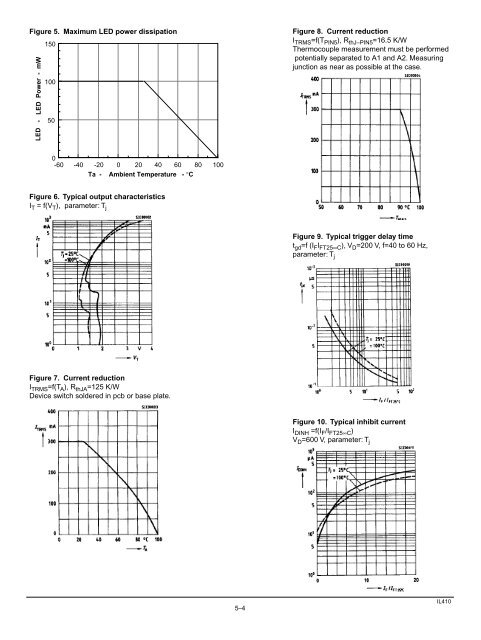
Figure 5. Maximum LED power dissipation<br />
P LED - LED Power - mW<br />
150<br />
100<br />
50<br />
Figure 8. Current reduction<br />
I TRMS =f(T PIN5 ), R thJ–PIN5 =16.5 K/W<br />
Thermocouple measurement must be performed<br />
potentially separated to A1 and A2. Measuring<br />
junction as near as possible at the case.<br />
0<br />
-60<br />
-40<br />
-20<br />
0<br />
20<br />
40<br />
60<br />
80<br />
100<br />
Ta - Ambient Temperature - °C<br />
Figure 6. Typical output characteristics<br />
I T = f(V T ), parameter: T j<br />
Figure 9. Typical trigger delay time<br />
t gd =f (I F I FT25∞C ), V D =200 V, f=40 to 60 Hz,<br />
parameter: T j<br />
Figure 7. Current reduction<br />
I TRMS =f(T A ), R thJA =125 K/W<br />
Device switch soldered in pcb or base plate.<br />
Figure 10. Typical inhibit current<br />
I DINH =f(I F /I FT25∞C )<br />
V D =600 V, parameter: T j<br />
5–4<br />
<strong>IL410</strong>