IL410 datasheet - Datasheet Catalog
IL410 datasheet - Datasheet Catalog
IL410 datasheet - Datasheet Catalog

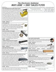
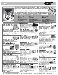
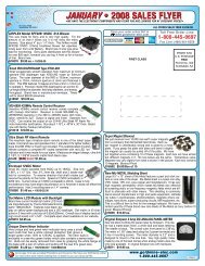
Create successful ePaper yourself
Turn your PDF publications into a flip-book with our unique Google optimized e-Paper software.
Technical Information<br />
Commutating Behavior<br />
The use of a triac at the output creates difficulties in commutation<br />
due to both the built-in coupled thyristor systems.<br />
The triac can remain conducting by parasitic triggering after<br />
turning off the control current. However, if the <strong>IL410</strong> is<br />
equipped with two separate thyristor chips featuring high dv/<br />
dt strength, no RC circuit is needed in case of commutation.<br />
Control And Turn-On Behavior<br />
The trigger current of the <strong>IL410</strong> has a positive temperature<br />
gradient. The time which expires from applying the control<br />
current to the turn-on of the load current is defined as the trigger<br />
delay time (tgd). On the whole this is a function of the<br />
overdrive meaning the ratio of the applied control current versus<br />
the trigger current (I F /I FT ). If the value of the control current<br />
corresponds to that of the individual trigger current of<br />
<strong>IL410</strong> turn-on delay times amounts to a few milliseconds only.<br />
The shortest times of 5 to 10 µs can be achieved for an overdrive<br />
greater or equal than 10. The trigger delay time rises<br />
with an increase in temperature.<br />
For very short control current pulses (t plF