Roof and Wall - Lane Roofing
Roof and Wall - Lane Roofing
Roof and Wall - Lane Roofing

Create successful ePaper yourself
Turn your PDF publications into a flip-book with our unique Google optimized e-Paper software.
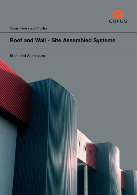
Corus Panels <strong>and</strong> Profiles<br />
<strong>Roof</strong> <strong>and</strong> <strong>Wall</strong> - Site Assembled Systems<br />
Steel <strong>and</strong> Aluminium
Introduction<br />
The total<br />
envelope<br />
solution<br />
2 <strong>Roof</strong> & <strong>Wall</strong> - Site Assembled Systems
Introduction<br />
Corus Panels <strong>and</strong> Profiles operate from factories in<br />
South Wales <strong>and</strong> Gloucestershire <strong>and</strong> have served<br />
clients in the construction industry for over 40 years.<br />
The comprehensive Corus Panels <strong>and</strong><br />
Profiles product range includes:<br />
• Composite roof <strong>and</strong> wall panels<br />
•Architectural modular<br />
panels (facades)<br />
• Structural roof decking<br />
• Composite Flooring Systems<br />
• St<strong>and</strong>ing Seam <strong>Roof</strong>ing<br />
•Fire protection systems<br />
• Acoustic Systems<br />
• Bespoke Solutions<br />
External Sales<br />
An experienced team of specialist<br />
sales consultants is available to<br />
support specifiers <strong>and</strong> contractors<br />
both in the UK <strong>and</strong> overseas.<br />
Technical Support<br />
Comprehensive technical support is<br />
available to offer advice on the<br />
design <strong>and</strong> performance of Corus<br />
Panels <strong>and</strong> Profiles products.<br />
Research <strong>and</strong> Development<br />
Corus Panels <strong>and</strong> Profiles has<br />
access to world class testing <strong>and</strong><br />
development facilities.<br />
<strong>Roof</strong> & <strong>Wall</strong> - Site Assembled Systems 3
St<strong>and</strong>ard <strong>Roof</strong> Profile Range<br />
St<strong>and</strong>ard roof profile range<br />
Corus Panels <strong>and</strong> Profiles offer an attractive <strong>and</strong> economic<br />
range of roof profiles to meet both the aesthetic <strong>and</strong><br />
structural requirements of the designer.<br />
R13.5/3<br />
Cover width 990.6 (Alternative 980)<br />
19<br />
R32/1000<br />
Cover width 1000<br />
27<br />
76.2<br />
(Alternative 75.38)<br />
32<br />
R35A<br />
Cover width 900<br />
150<br />
200 127.5<br />
35<br />
35<br />
CLS Laundry, Newton Abbott.<br />
R38A<br />
R40<br />
R46<br />
R60<br />
Clipfix 750<br />
Seam–Loc<br />
ALU–SEAM ®<br />
75<br />
Cover width 914.4<br />
38<br />
19<br />
152.4 82<br />
Cover width 1000<br />
31<br />
40<br />
242<br />
333.3<br />
Cover width 900<br />
46<br />
67<br />
105 225<br />
Cover width 800<br />
60<br />
64<br />
200 90<br />
Cover width 750<br />
19.50 18.25 43.50<br />
46<br />
250<br />
4<br />
Cover width 410<br />
48<br />
205<br />
Cover width 410<br />
48<br />
205<br />
Load/span figures<br />
These tables are based on a total ‘dead’ <strong>and</strong> ‘super<br />
imposed’ load of 1.20 kN/m 2 <strong>and</strong> a deflection limit of<br />
L/200. The quoted spans are more onerous than the<br />
profiles maximum allowable spans when subjected to wind<br />
suction loads. Therefore, the tables can be used as a<br />
conservative guide for loading in either direction. For<br />
differing conditions please consult our full load tables<br />
<strong>and</strong>/or consult our Technical Services Department.<br />
Curving<br />
Self curving can induce stress marking in the sheet. The<br />
figures shown have been chosen with aesthetics in mind<br />
<strong>and</strong> therefore minimise visible induced stress. Self curved<br />
panel ends laps will ‘birdmouth’ slightly, therefore long<br />
sheet lengths are recommended to reduce the number of<br />
end laps. Factory curved data relates to a single convex<br />
curve. Information regarding double or wave curves must<br />
be obtained from Corus Panels <strong>and</strong> Profiles.<br />
Finishes<br />
The data held within this table concerns itself with our<br />
st<strong>and</strong>ard product range. Non st<strong>and</strong>ard materials, gauges,<br />
colours <strong>and</strong> coatings are available to special order, subject<br />
to quantity required <strong>and</strong> extended lead time.<br />
See page 10 for special roof profiles.<br />
Space Decks Headquarters, Chard.<br />
4 <strong>Roof</strong> & <strong>Wall</strong> - Site Assembled Systems
St<strong>and</strong>ard <strong>Roof</strong> Profile Range<br />
Material<br />
Gauge (mm)<br />
Weight (kg/m 2 )<br />
Load/Span –<br />
max span (mm) SS<br />
Load/Span –<br />
max span (mm) MS<br />
Minimum<br />
self curve (m)<br />
Minimum<br />
factory curve (mm)<br />
Minimum<br />
<strong>Roof</strong> Pitch<br />
R13.5/3 S 0.7 6.81 1200 1500 20 (h), 30 (p), 35 (mp) 1000* 10<br />
A 0.9 3.05 900 1200 20 (sa/ca), 25 (ma) 1000* 10<br />
R32/1000 S 0.7 6.75 1900 2000 40 (h), 50 (p), 55 (mp) 400 4<br />
A 0.9 3.02 1500 1800 40 (sa/ca), 45 (ma) 400 4<br />
R35A S 0.7 7.5 2100 2500 40 (h), 50 (p), 55 (mp) 400 4<br />
A 0.9 3.37 1600 1900 40 (sa/ca), 45 (ma) 400 4<br />
R38A S 0.7 7.38 2200 2700 40 (h), 50 (p), 55 (mp) 400 4<br />
A 0.9 3.31 1700 2100 40 (sa/ca), 45 (ma) 400 4<br />
R40 S 0.7 6.75 2000 2000 40 (h), 50 (p), 55 (mp) 400 4<br />
A 0.9 3.02 1600 1800 40 (sa/ca), 45 (ma) 400 4<br />
R46 S 0.7 7.5 2700 3200 55 (h), 65 (p), 70 (mp) 400 4<br />
A 0.9 3.36 2100 2600 55 (sa/ca), 60 (ma) 400 4<br />
Key<br />
S – Steel<br />
A – Aluminium<br />
h – HPS200 ® by Corus<br />
p – Colorcoat ® PVDF<br />
mp – Metallic PVDF/Celestia ®<br />
by Corus<br />
sa – Stucco embossed<br />
aluminium<br />
ca – Coated aluminium<br />
ma – Metallic coated<br />
aluminium<br />
SS – Single span<br />
MS – Multi span<br />
Before ordering it is important<br />
to confirm with Corus Panels<br />
<strong>and</strong> Profiles which side of the<br />
profile carries the main surface<br />
finish.<br />
All profiles comply to current<br />
MCRMA Tolerances.<br />
* Factory curve only applies to<br />
980 cover R13.5/3.<br />
R60 S 0.7 8.44 3300 3800 70 (h), 80 (p), 85 (mp) NA 4<br />
A 0.9 3.78 2600 3200 70 (sa/ca), 75 (ma) NA 4<br />
Clipfix 750 S 0.7 7.99 1500 1700 60 (h) N/A 1<br />
A 0.9 4.20 1400 1600 50 (sa), 55 (ca/ma) N/A 1<br />
Seam-loc S 0.7 7.99 1300 1800 65 (h) 16000 (h) 1.5<br />
35000 (p)<br />
38000 (mp)<br />
convex<br />
ALU-SEAM ® A 0.9 3.75 1500 2000 30 (sa/ca), 35 (ma) 8000 1.5<br />
convex<br />
Del Monte Unit,<br />
Team Valley, Tyneside.<br />
<strong>Roof</strong> & <strong>Wall</strong> - Site Assembled Systems 5
St<strong>and</strong>ard <strong>Wall</strong> Profile Range<br />
St<strong>and</strong>ard wall profile range<br />
C13.5/3<br />
C19<br />
C32/1000<br />
C32S<br />
C35A<br />
C38A<br />
Cover width 990.6 (Alternative 980)<br />
Cover width 1066.8<br />
25<br />
Cover width 1000<br />
76.2<br />
(Alternative 75.38)<br />
27 200<br />
Cover width 960<br />
160<br />
27<br />
Cover width 900<br />
150<br />
Cover width 914.4<br />
75<br />
87.5<br />
35<br />
82.4<br />
152.4<br />
95.4<br />
127.5<br />
38<br />
19<br />
19<br />
32<br />
32<br />
35<br />
Corus Panels <strong>and</strong> Profiles offer an attractive <strong>and</strong> economic<br />
range of wall profiles to meet both the aesthetic <strong>and</strong><br />
structural requirements of the designer.<br />
For flexibility of design these profiles can be reversed. In<br />
this situation the equivalent roof profile (‘R’ suffix) should<br />
be specified with side lap installed as per the roofing<br />
method.<br />
Curving<br />
Self curving can induce stress marking in the sheet. The<br />
figures shown have been chosen with aesthetics in mind<br />
<strong>and</strong> therefore minimise visible induced stress. End laps will<br />
‘birdmouth’ slightly on self curved cladding.<br />
Factory curved data relates to a single convex curve.<br />
Information regarding double or wave curves must be<br />
obtained from Corus Panels <strong>and</strong> Profiles.<br />
Horizontal applications<br />
Corus Panels <strong>and</strong> Profiles have indicated the profiles that,<br />
through experience have given good service when laid<br />
horizontally. This being based on the necessary greater<br />
attention being paid to in-plane steelwork tolerances.<br />
C46<br />
C60<br />
152.4<br />
Cover width 900<br />
105<br />
67<br />
C60<br />
Cover width 800<br />
WP40<br />
90<br />
64<br />
200<br />
40<br />
275 25<br />
225<br />
19<br />
46<br />
60<br />
Finishes<br />
The data held within this table concerns itself with our<br />
st<strong>and</strong>ard product range. Non st<strong>and</strong>ard materials, gauges,<br />
colours <strong>and</strong> coatings are available by special order, subject<br />
to quantity required <strong>and</strong> extended lead time.<br />
Load/span figures<br />
These tables are based on an effective positive wind load<br />
of 1.00 kN/m 2 <strong>and</strong> a deflection limit of L/150. The quoted<br />
spans are more onerous than the profiles maximum<br />
allowable spans when subjected to identical negative<br />
pressure/wind suction loads. Therefore, the tables can be<br />
used as a conservative guide for loading in either direction.<br />
For differing conditions please consult our full load tables<br />
<strong>and</strong>/or consult our Technical Services Department.<br />
See page 12 for special wall profiles.<br />
Attractive range of profiles<br />
Industrial Units 1& 2, New York, Tyneside.<br />
6 <strong>Roof</strong> & <strong>Wall</strong> - Site Assembled Systems
St<strong>and</strong>ard <strong>Wall</strong> Profile Range<br />
Material<br />
Gauge (mm)<br />
Weight (kg/m 2 )<br />
Load/Span –<br />
max span (mm) SS<br />
Load/Span –<br />
max span (mm) MS<br />
Minimum<br />
self curve (m)<br />
Minimum<br />
factory curve (mm)<br />
Suitable for<br />
Horizontal use<br />
C13.5/3 S 0.5 4.86 1200 1400 20 (h), 30 (p), 35 (mp) 1000* N<br />
0.7 6.79 1300 1600 20 (h), 30 (p), 35 (mp) 1000* Y<br />
A 0.9 3.05 1100 1400 20 (sa/ca), 25 (mp) 1000* Y<br />
C19 S 0.5 4.52 1400 1500 20 (h), 30 (p), 35 (mp) 350 N<br />
0.7 6.75 1500 1900 20 (h), 30 (p), 35 (mp) 350 Y<br />
A 0.9 3.02 1200 1500 20 (sa/ca), 25 (ma) 350 Y<br />
C32/1000 S 0.5 4.82 1800 1800 40 (h), 50 (p), 55 (mp) 400 N<br />
0.7 6.75 2100 2500 40 (h), 50 (p), 55 (mp) 400 Y<br />
A 0.9 3.02 1700 2100 40 (sa/ca), 45 (ma) 400 Y<br />
C32S S 0.5 5.02 2100 1900 40 (h), 50 (p), 55 (mp) NA N<br />
0.7 7.01 2300 2800 40 (h), 50 (p), 55 (mp) NA Y<br />
A 0.9 3.15 1800 2200 40 (sa/ca), 45 (ma) NA Y<br />
C35A S 0.5 5.35 2200 2100 40 (h), 50 (p), 55 (mp) 400 N<br />
0.7 7.2 2500 2900 40 (h), 50 (p), 55 (mp) 400 Y<br />
A 0.9 3.05 2000 2400 40 (sa/ca), 45 (ma) 400 Y<br />
Key<br />
S – Steel<br />
A – Aluminium<br />
h – HPS200 ® by Corus<br />
p – Colorcoat ® PVDF<br />
mp – Metallic PVDF/Celestia ®<br />
by Corus<br />
sa – Stucco embossed<br />
aluminium<br />
ca – Coated aluminium<br />
ma – Metallic coated<br />
aluminium<br />
SS – Single span<br />
MS – Multi span<br />
Before ordering it is important<br />
to confirm with Corus Panels<br />
<strong>and</strong> Profiles which side of the<br />
profile carries the main surface<br />
finish.<br />
All profiles comply to current<br />
MCRMA Tolerances.<br />
* Factory curve only applies to<br />
980 cover R13.5/3.<br />
C38A S 0.7 7.38 2500 3000 40 (h), 50 (p), 55 (mp) 400 Y<br />
A 0.9 3.31 2000 2400 40 (sa/ca), 45 (ma) 400 Y<br />
C46 S 0.5 5.35 2800 2200 55 (h), 65 (p), 70 (mp) 400 N<br />
0.7 7.5 3100 3600 55 (h), 65 (p), 70 (mp) 400 Y<br />
A 0.9 3.36 2400 3000 55 (sa/ca), 60 (ma) 400 Y<br />
C60 S 0.5 6.03 3400 2600 70 (h), 80 (p), 85 (mp) NA N<br />
0.7 8.44 3900 4000 70 (h), 80 (p), 85 (mp) NA Y<br />
A 0.9 3.78 3000 3700 70 (sa/ca), 75 (ma) NA Y<br />
WP40 S 0.7 7.50 2000 2200 60 (h), 70 (p), 75 (mp) 400 N<br />
A 0.9 3.36 1700 2000 60 (sa/ca), 65 (h) 400 N<br />
Suncrest Surrounds Ltd., Co.Durham.<br />
<strong>Roof</strong> & <strong>Wall</strong>- Site Assembled Systems 7
St<strong>and</strong>ard Lining Profiles Range<br />
St<strong>and</strong>ard lining profiles range<br />
Corus Panels <strong>and</strong> Profiles offer a range of lining panels<br />
specifically developed to be compatible with our outer<br />
sheet product range thus allowing the accommodation of<br />
modular rooflights.<br />
CL6/914<br />
CL6/914<br />
Perf (20%)<br />
152.4<br />
Cover width 914.4<br />
25<br />
57<br />
95.4<br />
19<br />
Lengths<br />
Being roll formed, long lengths are available but for<br />
practical site h<strong>and</strong>ling purposes with the 0.40 mm gauge<br />
options we would suggest these are kept to a maximum<br />
of 5m.<br />
LP1000<br />
LP1000<br />
Perf (21.5%)<br />
166.7<br />
Cover width 1000<br />
25 53.5 8<br />
60<br />
106.7<br />
19<br />
Vapour Barrier<br />
All non-perforated profiles provide a side lap which can be<br />
sealed to provide a vapour check. A correctly sealed lining<br />
panel will easily meet the 10m 3 /hr/m 2 @ 50 pascals air<br />
tightness requirement of the new building regulations.<br />
1000/19 †<br />
1000/19 †<br />
Perf (33%)<br />
C19<br />
C19<br />
Perf (20%)<br />
RL32/1000<br />
RL32/1000<br />
Perf (22%)<br />
15-20<br />
250<br />
152.4<br />
200<br />
Cover width 1000<br />
144 106 106 19<br />
19<br />
Cover width 1066.8<br />
25 16 57<br />
19<br />
95.4<br />
Cover width 1000<br />
27<br />
32<br />
127.5<br />
Spans<br />
In roofing conditions, the spanning capabilities of the lining<br />
panels are largely dependent upon their self-weight <strong>and</strong> the<br />
weight of the insulation they are required to support. In<br />
normal conditions with 0.40mm gauge liners double span<br />
capabilities of up to 2m can be achieved. However, at<br />
spans approaching maximum it may be necessary to<br />
mechanically fix side laps <strong>and</strong>/or reverse the normal side<br />
lap to minimise separation. The span for non fragility rating<br />
may be less than span shown in tables. Contact our<br />
Technical Department for fixing details to comply with<br />
ACR(M)001:2000.<br />
Fire Rating<br />
All non perforated lining sheets provide a fire rating of<br />
Class 1 to BS476: Part 7 <strong>and</strong> Class 0 in accordance with<br />
current Building Regulations.<br />
Due to the nature of pan perforating, some undulations may be evident in<br />
the final product.<br />
60 o 6.3 mm<br />
4.5mm diameter holes at<br />
6.3mm triangular centre<br />
Pattern open area - 46%<br />
Curving<br />
Self curving can induce stress marking in the sheet. The<br />
figures shown have been chosen with aesthetics in mind<br />
<strong>and</strong> therefore minimise visible induced stress. Figures are<br />
also based on the profile being fitted above the purlin on a<br />
convex curved roof. Factory curved data relates to a single<br />
convex curve. Information regarding double or wave curves<br />
must be obtained from Corus Panels <strong>and</strong> Profiles.<br />
Full design <strong>and</strong> installation guide available<br />
8 8 Secret <strong>Roof</strong> & Fix <strong>Wall</strong> Product - Site Selector Assembled Systems
St<strong>and</strong>ard Lining Profiles Range<br />
Material<br />
Gauge (mm)<br />
Weight (kg/m 2 )<br />
Load/Span –<br />
max span (mm) SS<br />
Load/Span –<br />
max span (mm) DS<br />
Minimum<br />
self curve (m)<br />
Minimum<br />
factory curve (mm)<br />
Working platform<br />
Compatible<br />
outer sheets if<br />
rooflights<br />
incorporated<br />
CL6/914 S 0.4 3.64 1600 2200 40 (le) 350 N R/C38A<br />
CL6/914 S 0.4 2.98 1300 1800 40 (le) 350 N R/C38A<br />
Perf (20%)<br />
LP1000 S 0.4 3.50 1600 2200 40 (le) 350 N R/C32/1000<br />
LP1000 S 0.4 2.84 1300 1800 40 (le) 350 N R/C32/1000<br />
Perf (21.5%)<br />
R40<br />
1000/19 † S 0.7 5.89 2000 2000 40 (le) 250 N Clipfix<br />
1000/19 † S 0.7 4.12 1800 1800 50 (le) 250 N Clipfix<br />
Perf (33%) A 0.9 2.70 1800 1800 40 (ca) 250 N Clipfix<br />
C19 S 0.7 6.33 2000 3000 20 (h), 30 (p/le), 35 (mp) 350 N R/C19<br />
R/C38A – (profile<br />
pitch compatible)<br />
A 0.9 2.84 1600 2200 20 (sa/ca), 25 (ma) 350 N R/C19<br />
R/C38A – (profile<br />
pitch compatible)<br />
C19 S 0.7 5.19 1700 2500 20 (h), 30 (p/le), 35 (mp) 350 N R/C19<br />
Perf (20%)<br />
R/C38A – (profile<br />
pitch compatible)<br />
A 0.9 2.33 1300 1800 20 (sa/ca), 25 (ma) 350 N R/C19<br />
R/C38A – (profile<br />
pitch compatible)<br />
RL32/1000 S 0.7 6.75 2500 3200 40 (h), 50 (p/le), 55 (mp) 400 Y* R/C32/1000<br />
R40<br />
A 0.9 3.03 2000 2600 40 (sa/ca), 45 (ma) 400 Y ‡ R/C32/1000<br />
RL32/1000 S 0.7 6.75 2100 2700 40 (h), 50 (p/le), 55 (mp) 400 N R/C32/1000<br />
Perf (22%)<br />
R40<br />
A 0.9 2.43 1700 2200 40 (sa/ca), 45 (ma) 400 N R/C32/1000<br />
R40<br />
R40<br />
R40<br />
Key<br />
S – Steel<br />
A – Aluminium<br />
h – HPS200 ® by Corus<br />
p – Colorcoat ® PVDF<br />
mp – Metallic PVDF/Celestia ®<br />
by Corus<br />
sa – Stucco embossed<br />
aluminium<br />
ca – Coated aluminium<br />
ma – Metallic coated<br />
aluminium<br />
SS – Single span<br />
DS – Double span<br />
Before ordering it is important<br />
to confirm with Corus Panels<br />
<strong>and</strong> Profiles which side of the<br />
profile carries the main surface<br />
finish.<br />
All profiles comply to current<br />
MCRMA Tolerances.<br />
† Only available with Clipfix.<br />
* Maximum 2m centres<br />
suggested platform for<br />
ALU-SEAM ® roofs<br />
without lights<br />
‡<br />
Maximum 1.8m centres<br />
suggested platform for<br />
ALU-SEAM ® roofs<br />
without lights<br />
Finishes<br />
The data held within this table concerns itself with our<br />
st<strong>and</strong>ard product range. Non st<strong>and</strong>ard materials, gauges,<br />
colours <strong>and</strong> coatings are available to special order, subject<br />
to quantity required <strong>and</strong> extended lead time.<br />
Acoustics<br />
To meet the increasing dem<strong>and</strong> for noise reduction in<br />
factories <strong>and</strong> public buildings Corus Panels <strong>and</strong> Profiles<br />
can supply lining panels with acoustic perforations<br />
incorporated in the flat pans of the profile.<br />
When correctly installed, these panels can provide a high<br />
level of acoustic absorbency instead of the reflective finish<br />
normally presented by plain metal sheeting. Whilst other<br />
patterns can be achieved the st<strong>and</strong>ard pattern is illustrated<br />
in the table opposite. Percentage open areas are<br />
highlighted next to the relevant profiles.<br />
See page 14 for special lining profiles.<br />
Space Decks Headquarters, Chard.<br />
<strong>Roof</strong> & <strong>Wall</strong> - Site Assembled Systems 9
Lining Trays & Special <strong>Roof</strong> Profiles<br />
Structural lining trays<br />
Corus Panels <strong>and</strong> Profiles can offer a structural lining tray<br />
that is suitable for both roof <strong>and</strong> wall cladding applications<br />
spanning across the main steels <strong>and</strong> omitting the need for<br />
HL600/130<br />
purlins or cladding rails.<br />
Load/span figures<br />
38.50 60<br />
130<br />
These figures are based on a maximum load of 1.50kN/m 2<br />
<strong>and</strong> a deflection limit of L/200.<br />
HL600/130<br />
Perf (36%)<br />
Cover width 600<br />
Material<br />
Gauge (mm)<br />
Weight (kg/m 2 )<br />
Load/Span –<br />
max span (mm) SS<br />
Load/Span –<br />
max span (mm) DS<br />
Working platform<br />
HL600/130 S 1.00 13.08 6000 6000 Y<br />
HL600/130 S 0.75 9.81 5000 5000 N<br />
Perf (36%)<br />
Special roof profiles<br />
In order to offer the specifier more choice, it is possible to<br />
produce some of our more specialist sections adapted to<br />
suit roof cladding applications. The necessary modifications<br />
render these profiles ‘special’ <strong>and</strong> therefore may be subject<br />
to a minimum order requirement <strong>and</strong> extended lead times.<br />
R19<br />
1000/19<br />
Protile<br />
R100<br />
Cover width 1066.8<br />
152.4<br />
25<br />
95.4 57<br />
Cover width 1000<br />
15-20<br />
106 106<br />
250 144<br />
19<br />
Cover width 700<br />
233.3<br />
63<br />
100<br />
19<br />
19<br />
For further information please contact our Sales Department.<br />
Load/span figures<br />
These tables are based on a total ‘dead’ <strong>and</strong> ‘super<br />
imposed’ load of 1.20 kN/m 2 <strong>and</strong> a deflection limit of L/200.<br />
The quoted spans are more onerous than the profiles<br />
maximum allowable spans when subjected to wind suction<br />
loads. Therefore, the tables can be used as a conservative<br />
guide for loading in either direction. For differing conditions<br />
please consult our full load tables <strong>and</strong>/or consult our<br />
Technical Services Department.<br />
Gauges<br />
The data held within this table concerns itself with the<br />
minimum recommended gauges. Different gauges, colours,<br />
coatings etc. can be made available subject to special order.<br />
109<br />
37<br />
See page 4 for st<strong>and</strong>ard roof profiles.<br />
Full design <strong>and</strong> installation guide available<br />
10 <strong>Roof</strong> & <strong>Wall</strong> - Site Assembled Systems
Lining Trays & Special <strong>Roof</strong> Profiles<br />
Material<br />
Gauge (mm)<br />
Weight (kg/m 2 )<br />
Load/Span –<br />
max span (mm) SS<br />
Load/Span –<br />
max span (mm) MS<br />
Minimum<br />
self curve (m)<br />
Minimum<br />
factory curve (mm)<br />
Minimum roof pitch<br />
R19 S 0.7 6.43 1300 1700 20 (h), 30 (p), 35 (mp) 400 10<br />
A 0.9 2.89 1000 1300 20 (sa/ca), 25 (ma) 400 10<br />
1000/19<br />
Protile<br />
S 0.7 5.89 666 666 † NA 10<br />
R100 S 0.7 9.80 5200 5600 110 (h), 120 (p), 125 (mp) NA 4<br />
A 0.9 4.41 3800 4600 110 (sa/ca), 115 (ma) NA 4<br />
Key<br />
S – Steel<br />
A – Aluminium<br />
h – HPS200 ® by Corus<br />
p – Colorcoat ® PVDF<br />
mp – Metallic PVDF/Celestia ®<br />
by Corus<br />
sa – Stucco embossed<br />
aluminium<br />
ca – Coated aluminium<br />
ma – Metallic coated<br />
aluminium<br />
SS – Single span<br />
MS – Multi span<br />
DS – Double span<br />
† – Contact technical<br />
department<br />
Before ordering it is important<br />
to confirm with Corus Panels<br />
<strong>and</strong> Profiles which side of the<br />
profile carries the main<br />
surface finish.<br />
All profiles comply to current<br />
MCRMA Tolerances.<br />
Above: Winchester House School, Sports Hall, Winchester.<br />
Right: Zenith, Basildon.<br />
<strong>Roof</strong> & <strong>Wall</strong> - Site Assembled Systems 11
Special <strong>Wall</strong> Profiles<br />
Special wall profiles<br />
CH47<br />
150<br />
Cover width 900<br />
100<br />
47<br />
52<br />
29<br />
Arcline 40<br />
Cover width 1000<br />
40<br />
200<br />
40<br />
In order to offer the specifier more choice, it is possible to<br />
produce some of our more specialist sections adapted to<br />
suit wall cladding applications.<br />
The necessary modifications render these profiles ‘special’<br />
<strong>and</strong> therefore may be subject to minimum order<br />
requirements <strong>and</strong> extended lead times. For further<br />
information please contact our Sales Department.<br />
Material<br />
Gauge (mm)<br />
Weight (kg/m 2 )<br />
Load/Span –<br />
max span (mm) SS<br />
Load/Span –<br />
max span (mm) MS<br />
Gauges<br />
The data held within this table concerns itself with the<br />
minimum recommended gauges.<br />
Different gauges, colours, coatings etc.<br />
can be made available<br />
subject to special order.<br />
Key<br />
See page 6 for st<strong>and</strong>ard wall profiles.<br />
Minimum<br />
self curve (m)<br />
Minimum<br />
factory curve (mm)<br />
Horizontal<br />
Applications<br />
CH47 S 0.7 6.56 2100 2600 70 (h), 80 (p), 85 (mp) NA Horizontal only<br />
S – Steel<br />
A – Aluminium<br />
h – HPS200 ® by Corus<br />
p – Colorcoat ® PVDF<br />
mp – Metallic PVDF/Celestia ®<br />
by Corus<br />
sa – Stucco embossed<br />
aluminium<br />
ca – Coated aluminium<br />
ma – Metallic coated<br />
aluminium<br />
SS – Single span<br />
MS – Multi span<br />
Before ordering it is important<br />
to confirm with Corus Panels<br />
<strong>and</strong> Profiles which side of the<br />
profile carries the main surface<br />
finish.<br />
Arcline 40 S 0.7 6.74 2200 2400 50 (h), 60 (p), 65 (mp) NA Y<br />
All profiles comply to current<br />
MCRMA Tolerances.<br />
Full design <strong>and</strong> installation guide available<br />
12 <strong>Roof</strong> & <strong>Wall</strong> - Site Assembled Systems
Special <strong>Wall</strong> Profiles<br />
Left: The Enigma Building, Milton Keynes.<br />
Above: Horizon Point, Hemel Hempsted.<br />
<strong>Roof</strong> & <strong>Wall</strong> - Site Assembled Systems 13
Special Lining Profiles<br />
Special lining profiles<br />
CL3/1000<br />
10<br />
1000<br />
25 2.5<br />
333.33<br />
19<br />
CL3/1000<br />
Perf (27%)<br />
67.4 81.5<br />
67.4<br />
57<br />
30<br />
30<br />
10<br />
In order to offer the specifier more choice, it is possible to<br />
produce some of our more specialist sections adapted to<br />
suit wall cladding applications.<br />
The necessary modifications render these profiles ‘special’<br />
<strong>and</strong> therefore may be subject to minimum order<br />
requirements <strong>and</strong> extended lead times. For further<br />
information please contact our Sales Department.<br />
Material<br />
Gauge (mm)<br />
Weight (kg/m 2 )<br />
Load/Span –<br />
max span (mm) SS<br />
Load/Span –<br />
max span (mm) DS<br />
Minimum<br />
self curve (m)<br />
Gauges<br />
The data held within this table concerns itself with the<br />
minimum recommended gauges.<br />
Different gauges, colours, coatings etc. Key<br />
can be made available subject to<br />
S – Steel<br />
A – Aluminium<br />
special order<br />
See page 8 for st<strong>and</strong>ard lining profiles.<br />
Minimum<br />
factory curve (mm)<br />
CL3/1000 S 0.4 3.32 1500 2000 40 300 N R32/1000 & R40<br />
CL3/1000 S 0.4 2.42 1200 1700 40 300 N R32/1000 & R40<br />
Perf (27%)<br />
Working platform<br />
Compatible<br />
outer sheets if<br />
rooflights<br />
incorporated<br />
h – HPS200 ® by Corus<br />
p – Colorcoat ® PVDF<br />
mp – Metallic PVDF/Celestia ®<br />
by Corus<br />
sa – Stucco embossed<br />
aluminium<br />
ca – Coated aluminium<br />
ma – Metallic coated<br />
aluminium<br />
SS – Single span<br />
DS – Double span<br />
Before ordering it is important<br />
to confirm with Corus Panels<br />
<strong>and</strong> Profiles which side of the<br />
profile carries the main surface<br />
finish.<br />
All profiles comply to current<br />
MCRMA Tolerances.<br />
* Factory curve only applies to<br />
980 cover R13.5/3.<br />
Above: Space Decks Headquarters, Chard.<br />
14 <strong>Roof</strong> & <strong>Wall</strong> - Site Assembled Systems
Pressed Profiles<br />
Pressed profiles, wall cladding, fascias <strong>and</strong> soffit lining<br />
Pressed profiles are manufactured by brake press, which<br />
offers flexibility in their design but limits the overall length<br />
to 3.6metres. The brake press tool creates the rib profile<br />
which means that the shape of this is fixed, however the<br />
PR8<br />
145<br />
Cover width 1160<br />
107<br />
38<br />
25<br />
8<br />
spacing of ribs may be varied to create interesting<br />
aesthetic effects. Thus the crown <strong>and</strong> pitch are variable but<br />
the rib shape is not. The minimum pitch available for each<br />
profile is shown opposite.<br />
PM13<br />
Cover width 1085<br />
133<br />
22<br />
13<br />
Pressed profiles are used for fascias, soffits <strong>and</strong> to create<br />
architectural effects such as infill panels in wall cladding.<br />
155<br />
13<br />
PL19<br />
Cover width 1050<br />
93<br />
57<br />
19<br />
150<br />
25<br />
PG22<br />
Cover width 990<br />
105<br />
60<br />
22<br />
PS47<br />
165<br />
160<br />
Cover width 800<br />
82<br />
28<br />
Material<br />
78<br />
Gauge (mm)<br />
38<br />
47<br />
Weight (kg/m 2 )<br />
Load/Span –<br />
max span (mm) SS<br />
Load/Span –<br />
max span (mm) DS<br />
Minimum<br />
self curve (m)<br />
PR8 S 0.7 5.73 800 900 20 100<br />
PM13 S 0.7 6.05 900 1000 20 75 This profile cannot<br />
be end lapped<br />
PL19 S 0.7 6.22 1400 1600 20 90<br />
PG22 S 0.7 6.54 1600 1700 30 150<br />
PS47 S 0.7 7.82 2600 2800 60 125<br />
Minimum pitch (mm)<br />
Key<br />
S – Steel<br />
SS – Single span<br />
DS – Double span<br />
Before ordering it is important<br />
to confirm with Corus Panels<br />
<strong>and</strong> Profiles which side of the<br />
profile carries the main<br />
surface finish..<br />
All profiles comply to current<br />
MCRMA Tolerances.<br />
Finishes<br />
Lining enamel<br />
HPS200 ® by Corus<br />
Colorcoat ® PVDF<br />
Metallic PVDF<br />
Celestia ® by Corus<br />
Stucco embossed aluminium<br />
Coated aluminium<br />
Metallic coated aluminium<br />
Above: Newcastle Central Train Station, Newcastle-Upon-Tyne.<br />
<strong>Roof</strong> & <strong>Wall</strong> - Site Assembled Systems 15
Firewall Systems<br />
Fire protection design guide<br />
using steel wall cladding<br />
The use of insulated profiled steel<br />
cladding sheets is common practice<br />
for external wall constructions on a<br />
variety of different building types.<br />
However, in certain situations these<br />
walls are required to provide fire<br />
protection <strong>and</strong> in these instances<br />
specific Building Regulations have to<br />
be complied with. Corus Panels <strong>and</strong><br />
Profiles offer a range of nonloadbearing<br />
fully insulated fire<br />
resistant wall cladding systems<br />
available to meet Building Regulation<br />
requirements for one hour <strong>and</strong> four<br />
hour rated external boundary walls<br />
<strong>and</strong> one hour separating/partitional<br />
wall conditions.<br />
This publication has been produced to<br />
offer guidance on the methods<br />
developed for fire containment when<br />
using our coated steel cladding<br />
products.<br />
General Construction Requirements<br />
Support Structures<br />
Sheeting Rails<br />
To accommodate the thermal<br />
expansion generated during fire all<br />
sheeting rails must be fixed to support<br />
cleats with slotted holes <strong>and</strong> bolts used<br />
must have both steel <strong>and</strong> plastic low<br />
melt washers under the head.<br />
The rails should be positioned to create<br />
maximum support centres for the<br />
firewall not greater than 2m. Allowance<br />
must be made for expansion in the rail<br />
length <strong>and</strong> span condition for the rails<br />
themselves should be single but may be<br />
sleeved to achieve continuity.<br />
Structural Frame<br />
When sheeting rails heat up during a fire<br />
they cease to function as structural<br />
members. Therefore, to prevent the wall<br />
moving downwards under its own self<br />
weight either a support at the head or<br />
base of the wall is required. All Corus<br />
Panels <strong>and</strong> Profiles firewalls can be<br />
designed to be supported<br />
from eaves<br />
beams/stanchions or<br />
rafters <strong>and</strong> posts if<br />
situated on a gable end.<br />
However, these elements<br />
must be protected using conventional fire<br />
protection materials to give the same<br />
period of fire resistance as the firewall.<br />
Cavity Barriers<br />
Where a cavity is created within the wall<br />
construction cavity barriers are required<br />
to be introduced at positions identified<br />
by Building Regulations Approved<br />
Document B.<br />
On firewalls which use non-combustible<br />
mineral fibre insulant <strong>and</strong> where the<br />
design allows the quilt/board to<br />
effectively seal the cavity against the<br />
steel sheeting no additional barrier is<br />
necessary. However, on systems where<br />
the design incorporates an air gap a<br />
cavity barrier is required positioned to<br />
the full height of the wall at intervals not<br />
exceeding 20m.<br />
The basic technical performance<br />
requirement for a cavity barrier is that it<br />
must maintain integrity for 30 minutes<br />
<strong>and</strong> provide at least 15 minutes fire<br />
insulation as determined by test in<br />
accordance with BS476 Part 22.<br />
Cavity barriers should be fixed in a<br />
manner that prevents displacement<br />
under normal service conditions or in<br />
a fire.<br />
16 Firewall Systems
Introduction<br />
Firewall System Selector<br />
Construction Fire resistance Insulation Exposed Boundary CP&P WFRC*<br />
Firewall System Orientation Type period (stability criteria face distance drawing certificate<br />
<strong>and</strong> integrity (mins.) No. No.<br />
-hours)<br />
Rockfibre Trinsul Vertical Outside rail 4 60 Either within 1m T1155 C127164<br />
Firewall<br />
face<br />
Double Skin Firewall<br />
with Instaloc 40 Vertical Outside rail 4 15 Inside 1m or T1007 C107677<br />
Spacer System & face more<br />
Glassfibre Quilt<br />
Double Skin Firewall<br />
with Instaloc 40 Vertical Outside rail 4 15 Inside 1m or T1014 C107675<br />
Spacer System & face more<br />
Rockfibre Quilt<br />
Double Skin Firewall<br />
with Instaloc 40 Vertical Outside rail 4 30 Inside 1m or – 141917<br />
Spacer System & face more<br />
Rockfibre Quilts<br />
Paramount Systems Vertical Outside rail 4 30 Inside 1m or – 131145<br />
face more<br />
Structural Liner Tray Vertical Liner Tray 4 15 Inside 1m or T1150 C54353<br />
Firewall face more<br />
Structural Liner Tray Vertical Liner Tray 4 60 Either Within T1151 C80289<br />
Firewall face 1m<br />
Double Skin Firewall Horizontal Inside rail 4 15 Inside 1m or T1003 C107659<br />
Quilt Insulated face more<br />
Double Skin Firewall Vertical Inside rail 4 30 Either Within T1170 C52869<br />
Quilt Insulated face 1m<br />
* Warrington Fire Research Centre Limited.<br />
Firewall Systems 17
4 Hour<br />
1 Hour Insulation 4 Hour Integrity<br />
Rockfibre Trinsul Firewall (vertical outside rail)<br />
Corus Panels <strong>and</strong> Profiles Rockfibre<br />
Trinsul outside rail cladding system<br />
has a 1 hour fire resistance from<br />
either direction when fixed within<br />
1 metre of relevant boundary.<br />
Insulation<br />
80kg/m 3 nominal density profiled<br />
rockfibre trinsul insulation board.<br />
Minimum thickness to achieve<br />
0.35W/m 2 K ‘U’ value.<br />
Lining Panel<br />
Corus Panels <strong>and</strong> Profiles colorcoated<br />
galvanised steel 0.4/0.7mm thick.<br />
Sheeting Rail<br />
Sheeting rails supplied by others.<br />
The rail is not fire protected but a facility<br />
for expansion is required (slotted fixing<br />
holes).<br />
LPC<br />
Rockfibre Trinsul meets fully the<br />
requirements of part 2.2 of the LPC<br />
design guide for the fire protection of<br />
buildings 2000.<br />
Outer Cladding<br />
Corus Panels <strong>and</strong> Profiles colorcoated<br />
galvanised steel 0.5/0.7mm thick.<br />
Construction Notes<br />
All fixings <strong>and</strong> components to be steel.<br />
All outer sheet side laps must be stitched<br />
at not more than 400mm centres.<br />
Lining panel does not require stitching.<br />
Warrington Fire Research Centre number<br />
C127164.<br />
The Building Regulations 2000<br />
Approved Document L2 – April 2002<br />
Contact Corus Panels <strong>and</strong> Profiles<br />
Technical Department for information on<br />
the insulation thickness needed for this<br />
system to meet part L requirements.<br />
18 Firewall Systems
4 Hour<br />
15 minutes Insulation 4 Hour Integrity<br />
Double Skin Firewall with Instaloc 40 Spacer System<br />
& Glassfibre Quilt (vertical outside rail)<br />
This system is intended for use as<br />
an external wall, sited at least 1 metre<br />
from a relevant boundary. It is not<br />
suitable for partitions.<br />
Assessment of fire resistance refers<br />
to cladding system which must be<br />
supported at base or by a fire rated<br />
eaves beam. The assessment refers<br />
to non-load bearing walls. The<br />
cladding system carries no vertical<br />
load other than its own dead weight.<br />
Installation of this system to be in<br />
accordance with approved document<br />
B (Fire Spread) in the Building<br />
Regulations 2000.<br />
Insulation<br />
Glassfibre insulation quilt, minimum<br />
thickness 160mm. 10kg/m 3 nominal<br />
density.<br />
Lining Panel<br />
Corus Panels <strong>and</strong> Profiles colorcoated<br />
galvanised steel 0.4/0.7mm thick.<br />
Sheeting Rail<br />
Sheeting rails supplied by others. The rail<br />
is not fire protected but a facility for<br />
expansion is required (slotted fixing holes).<br />
Instaloc 40<br />
200mm bracket is required with 160mm<br />
insulation. If insulation thickness is<br />
increased a minimum air gap of 40mm<br />
must be maintained.<br />
Outer Cladding<br />
Corus Panels <strong>and</strong> Profiles colorcoated<br />
galvanised steel 0.5/0.7mm thick.<br />
Construction Notes<br />
All fixings <strong>and</strong> components to be steel.<br />
All outer sheet side laps must be stitched<br />
at not more than 600mm centres <strong>and</strong> lining<br />
panels at not more than 300mm centres.<br />
The Building Regulations 2000 Approved Document L2 – April 2002<br />
Contact Corus Panels <strong>and</strong> Profiles Technical Department for information on the<br />
insulation thickness needed for this system to meet part L requirements.<br />
Original fire report by SGS Yarsley No.<br />
J88627/2 now updated by Warrington<br />
Fire Research Centre Ltd. to WFRC number<br />
C107677.<br />
System assessment to comply with BS476<br />
part 22.1987 in relation to internal fire.<br />
Stability = 240 minutes<br />
Integrity = 240 minutes<br />
Insulation = 15 minutes<br />
Firewall Systems 19
4 Hour<br />
15 minutes Insulation 4 Hour Integrity<br />
Double Skin Firewall with Instaloc 40 Spacer System<br />
& Rockfibre Quilt (vertical outside rail)<br />
This system is intended for use<br />
as an external wall, sited at least<br />
1 metre from a relevant boundary.<br />
It is not suitable for partitions.<br />
Assessment of fire resistance refers<br />
to cladding system which must be<br />
supported at base or by a fire rated<br />
eaves beam. The assessment refers<br />
to non-loadbearing walls. The<br />
cladding system carries no vertical<br />
load other than its own dead weight.<br />
Installation of this system to be<br />
in accordance with approved<br />
document B (Fire Spread) in the<br />
Building Regulations 2000.<br />
Instaloc 40<br />
120mm bracket is required with 120mm<br />
insulation. For thicker insulation increase<br />
bracket size accordingly.<br />
The Building Regulations 2000<br />
Approved Document L2 – April<br />
2002<br />
Contact Corus Panels <strong>and</strong> Profiles<br />
Technical Department for information<br />
on the insulation thickness needed for<br />
this system to meet part L<br />
requirements.<br />
Insulation<br />
Rockfibre insulation quilt, minimum thickness<br />
120mm. 23kg/m 3 nominal density.<br />
Lining Panel<br />
Corus Panels <strong>and</strong> Profiles colorcoated<br />
galvanised steel 0.4/0.7mm thick.<br />
Sheeting Rail<br />
Sheeting rails supplied by others. The rail<br />
is not fire protected so a facility for<br />
expansion is required (slotted fixing holes).<br />
Outer Cladding<br />
Corus Panels <strong>and</strong> Profiles colorcoated<br />
galvanised steel 0.5/0.7mm thick.<br />
Construction Notes<br />
All fixings <strong>and</strong> components to be steel.<br />
All outer sheet side laps must be stitched<br />
at not more than 600mm centres.<br />
Lining panels do not require stitching.<br />
Warrington Fire Research Centre number<br />
C107675.<br />
System assessment to comply with BS476<br />
part 22.1987 in relation to internal fire.<br />
Stability = 240 minutes<br />
Integrity = 240 minutes<br />
Insulation = 15 minutes<br />
20 Firewall Systems
4 Hour<br />
30 minutes Insulation 4 Hour Integrity<br />
Double Skin Firewall with Instaloc 40 Spacer System<br />
& Rockfibre Quilt (vertical outside rail)<br />
This system is intended for use<br />
as an external wall, sited at least<br />
1 metre from a relevant boundary.<br />
It is not suitable for partitions.<br />
Assessment of fire resistance refers<br />
to cladding system which must be<br />
supported at base or by a fire rated<br />
eaves beam. The assessment refers<br />
to non-loadbearing walls. The<br />
cladding system carries no vertical<br />
load other than its own dead weight.<br />
Installation of this system to be<br />
in accordance with approved<br />
document B (Fire Spread) in the<br />
Building Regulations 2000.<br />
Insulation<br />
Two layers of 80mm thick Rockfibre<br />
insulation quilt. 23kg/m 3 nominal density.<br />
Lining Panel<br />
Corus Panels <strong>and</strong> Profiles colorcoated<br />
galvanised steel 0.4/0.7mm thick.<br />
Instaloc 40<br />
160mm bracket is required with 160mm<br />
insulation. For thicker insulation<br />
increase bracket size accordingly.<br />
Outer Cladding<br />
Corus Panels <strong>and</strong> Profiles colorcoated<br />
galvanised steel 0.5/0.7mm thick.<br />
Sheeting Rail<br />
Sheeting rails supplied by others.<br />
The rail is not fire protected so a facility<br />
for expansion is required (slotted fixing<br />
holes).<br />
Construction Notes<br />
All fixings <strong>and</strong> components to be<br />
steel.<br />
All outer sheet side laps must be<br />
stitched at not more than 600mm<br />
centres.<br />
Lining panels do not require stitching.<br />
The Building Regulations 2000<br />
Approved Document L2 – April 2002<br />
Contact Corus Panels <strong>and</strong> Profiles<br />
Technical Department for information on<br />
the insulation thickness needed for this<br />
system to meet part L requirements.<br />
Warrington Fire Research Centre<br />
number 141917.<br />
System assessment to comply with<br />
BS476 part 22.1987 in relation to<br />
internal fire.<br />
Stability = 240 minutes<br />
Integrity = 240 minutes<br />
Insulation = 30 minutes<br />
Firewall Systems 21
4 Hour<br />
30 minutes Insulation 4 Hour Integrity<br />
Paramount System<br />
This system is intended for use<br />
as an external wall, sited at least<br />
1 metre from a relevant boundary.<br />
It is not suitable for partitions.<br />
Assessment of fire resistance refers<br />
to cladding system which must be<br />
supported at base or by a fire rated<br />
eaves beam. The assessment refers<br />
to non-loadbearing walls. The<br />
cladding system carries no vertical<br />
load other than its own dead weight.<br />
Installation of this system to be<br />
in accordance with approved<br />
document B (Fire Spread) in the<br />
Building Regulations 2000.<br />
Insulation<br />
60mm rockfibre insulation.<br />
24kg/m 3 density. Minimum thickness to<br />
achieve 0.35W/m 2 K. ‘U’ value<br />
Sheeting Rail<br />
Sheeting rails supplied by others.<br />
The rail is not fire protected but a<br />
facility for expansion is required.<br />
Spacer<br />
60mm deep spacer system.<br />
Outer Cladding<br />
Trisomet Composite panel, 40mm thick,<br />
(PIR core) 1000mm cover width, laid<br />
vertically.<br />
Lining Panel<br />
LP1000 lining panel, 0.4mm thick.<br />
Construction Notes<br />
All outer sheet side laps must be<br />
stitched at maximum centres of 450mm.<br />
Lining panel side laps do not require<br />
stitching.<br />
Warrington Fire Research Centre<br />
number 131145.<br />
Suitable for low humidity buildings.<br />
For high humidity buildings contact<br />
our Technical Department.<br />
System assessment to comply with<br />
BS476 part 22.1987 in relation to<br />
internal fire.<br />
Stability = 240 minutes<br />
Integrity = 240 minutes<br />
Insulation = 30 minutes<br />
22 Firewall Systems
4 Hour<br />
15 Minutes Insulation 4 Hour Integrity<br />
Structural Liner Tray<br />
This system is intended for use<br />
as an external wall, sited at least<br />
1 metre from a relevant boundary.<br />
It is not suitable for partitions.<br />
Assessment of fire resistance refers<br />
to cladding system which must be<br />
supported at base or by a fire rated<br />
eaves beam. The assessment refers<br />
to non-loadbearing walls. The<br />
cladding system carries no vertical<br />
load other than its own dead weight.<br />
Installation of this system to be<br />
in accordance with approved<br />
document B (Fire Spread) in the<br />
Building Regulations 2000.<br />
Liner Tray<br />
Corus Panels <strong>and</strong> Profiles HL600/130<br />
Structural Liner Tray.<br />
Thermal Break Strip<br />
Rockfibre fire barrier strip<br />
50mm x 35mm 240kg/m 3 density.<br />
Fastener<br />
5.5mm diameter by 45mm long selfdrilling<br />
fastener e.g. SD3-T15-5.5x45.<br />
Side Stitching<br />
Side stitching in web at tray interlocks<br />
400mm maximum centres.<br />
Insulation<br />
Rockfibre insulation, minimum<br />
160mm thick 23kg/m 3 nominal density.<br />
Outer Cladding<br />
Corus Panels <strong>and</strong> Profiles External<br />
Cladding 0.5mm thick steel.<br />
Warrington Fire Research Centre number<br />
C54353.<br />
System assessment to comply with BS476<br />
part 22.1987 in relation to internal fire.<br />
Stability = 240 minutes<br />
Integrity = 240 minutes<br />
Insulation = 15 minutes<br />
The Building Regulations 2000 Approved<br />
Document L2 – April 2002<br />
The above achieves 0.35 W/m 2 K in<br />
accordance with Approved Document L2<br />
April 2002.<br />
Firewall Systems 23
4 Hour<br />
1 Hour Insulation 4 Hour Integrity<br />
Structural Liner Tray<br />
This system can be used for an<br />
external or internal partition wall, sited<br />
within 1 metre from a relevant<br />
boundary. It is suitable for partitions.<br />
Assessment of fire resistance refers<br />
to cladding system which must be<br />
supported at base or by a fire rated<br />
eaves beam. The assessment refers<br />
to non-loadbearing walls. The<br />
cladding system carries no vertical<br />
load other than its own dead weight.<br />
Installation of this system to be<br />
in accordance with approved<br />
document B (Fire Spread) in the<br />
Building Regulations 2000.<br />
Liner Tray<br />
Corus Panels <strong>and</strong> Profiles HL600/130<br />
Structural Liner Tray.<br />
Insulation<br />
Rockfibre insulation<br />
80mm x 100kg/m 3 .<br />
Insulation<br />
Rockfibre insulation<br />
50mm x 23kg/m 3 .<br />
Fastener<br />
5.5mm diameter by 45mm long selfdrilling<br />
fastener e.g. SD3-T15-5.5x45.<br />
Side Stitching<br />
Side stitching in web at tray interlocks<br />
400mm maximum centres.<br />
Insulation<br />
Rockfibre insulation, minimum 30mm thick<br />
100kg/m 3 nominal density.<br />
Outer Cladding<br />
Corus Panels <strong>and</strong> Profiles External<br />
Cladding 0.5mm thick steel.<br />
Warrington Fire Research Centre number<br />
C80289.<br />
System assessment to comply with BS476<br />
part 22.1987 in relation to internal fire.<br />
Stability = 240 minutes<br />
Integrity = 240 minutes<br />
Insulation = 60 minutes<br />
The Building Regulations 2000 Approved<br />
Document L2 – April 2002<br />
The above achieves 0.35 W/m 2 K in<br />
accordance with Approved Document L2<br />
April 2002.<br />
24 Firewall Systems
4 Hour<br />
15 Minutes Insulation 4 Hour Integrity<br />
Quilt Insulated Double Skin Firewall<br />
(horizontal/vertical inside rail)<br />
This system is intended for use<br />
as an external wall, sited at least<br />
1 metre from a relevant boundary.<br />
It is not suitable for partitions.<br />
Assessment of fire resistance refers<br />
to cladding system which must be<br />
supported at base or by a fire rated<br />
eaves beam. The assessment refers<br />
to non-loadbearing walls. The<br />
cladding system carries no vertical<br />
load other than its own dead weight.<br />
Installation of this system to be<br />
in accordance with approved<br />
document B (Fire Spread) in the<br />
Building Regulations 2000.<br />
Insulation<br />
160mm foil faced rockfibre. (WFRC<br />
number C43554).<br />
Lining Panel<br />
Corus Panels <strong>and</strong> Profiles colorcoated<br />
galvanised steel 0.4/0.7mm thick.<br />
The Building Regulations 2000 Approved<br />
Document L2 – April 2002<br />
Contact Corus Panels <strong>and</strong> Profiles<br />
Technical Department for information on<br />
the insulation thickness needed for this<br />
system to meet part L requirements.<br />
Warrington Fire Research Centre<br />
number: C107659 Horiztonal,<br />
C107670 Vertical.<br />
Sheeting Rail<br />
Sheeting rails supplied by others,<br />
to be 150mm minimum for 160mm foil<br />
faced rockfibre. The rail is not fire<br />
protected so a facility for expansion is<br />
required.<br />
For thicker insulation increase rail depth<br />
accordingly.<br />
Top Hat<br />
1.60mm or 2mm zinc coated steel top hat<br />
section 45mm deep by Corus Panels &<br />
Profiles. To be fixed with self drilling/self<br />
tapping fasteners, 2 at each sheeting rail.<br />
Outer Cladding<br />
Corus Panels <strong>and</strong> Profiles colorcoated<br />
galvanised steel 0.5/0.7mm thick.<br />
Can be fitted horizontally as shown or<br />
fitted vertically directly onto rail.<br />
Construction Notes - Horizontal<br />
All fixings <strong>and</strong> components to be steel.<br />
All joints in the insulation to be overlapped<br />
by 100mm <strong>and</strong> aluminium pins used to<br />
prevent joints from separating. Fix<br />
insulation to rails in accordance with<br />
insulation manufacturers recommendations<br />
(note that the cladding sheet does not pin<br />
insulation to rails in this system). Outer<br />
sheet to be stitched at 450mm centres.<br />
Lining panel does not require stitching<br />
when rockfibre insulation is used.<br />
Construction Notes - Vertical<br />
All fixings <strong>and</strong> components to be steel.<br />
All outer sheet side laps must be stitched<br />
at no more than 600mm centres. Lining<br />
panel does not require stitching with<br />
rockfibre insulation is used,<br />
otherwise to be stitched<br />
at 300mm.<br />
System assessment to comply with<br />
BS476 part 22.1987 in relation to<br />
internal fire.<br />
Stability = 240 minutes<br />
Integrity = 240 minutes<br />
Insulation = 15 minutes<br />
Firewall Systems 25
4 Hour<br />
30 Minutes insulation 4 Hour Integrity<br />
Fire exposure to both faces<br />
This system is intended for use<br />
as an external wall or partition.<br />
Assessment of fire resistance refers<br />
to cladding system which must be<br />
supported at base or by a fire rated<br />
eaves beam. The assessment refers<br />
to non-loadbearing walls. The<br />
cladding system carries no vertical<br />
load other than its own dead weight.<br />
Installation of this system to be<br />
in accordance with approved<br />
document B (Fire Spread) in the<br />
Building Regulations 2000.<br />
Insulation<br />
60mm rockfibre 23kg/m 3 nominal density.<br />
Fire<br />
Source<br />
Fire<br />
Source<br />
Rockfibre Fire Barrier Strip<br />
50mm x 12mm.<br />
Sheeting Rail<br />
Sheeting 150mm minimum.<br />
Outer Cladding<br />
Corus Panels <strong>and</strong> Profiles external sheet.<br />
Insulation<br />
60mm rockfibre 23kg/m 3 nominal density.<br />
Lining Panel<br />
Corus Panels & Profiles colorcoated<br />
galvanised steel 0.4/0.7 mm thick.<br />
Construction Notes<br />
All side laps to be stitched at 450mm<br />
centres.<br />
Warrington Fire Research Centre number<br />
C52869.<br />
System assessment to comply with BS476<br />
part 22.1987 in relation to internal fire.<br />
Stability = 240 minutes<br />
Integrity = 240 minutes<br />
Insulation = 30 minutes<br />
26 Firewall Systems
Building Regulations<br />
Firewall Building Regulations<br />
The Building Regulations Approved<br />
Document B - 2000 edition provides<br />
guidelines on acceptable forms of fire<br />
resistant structures encompassing<br />
construction, material performance, means<br />
of escape <strong>and</strong> appropriate active fire control<br />
techniques. These are categorised in the<br />
following requirements:<br />
B1 – Means of escape<br />
B2 – Internal Fire Spread (linings)<br />
B3 – Internal Fire Spread (structure)<br />
B4 – External Fire Spread<br />
B5 - Access & Facilities for the Fire<br />
Service<br />
All of these stipulations require close design<br />
integration in order to establish effective<br />
building fire containment systems <strong>and</strong><br />
suitable evacuation procedures.<br />
Whilst for the purpose of this brochure it is<br />
impractical to cover all the conditions<br />
contained within this document,<br />
Requirements B2 <strong>and</strong> B4 are the most<br />
relevant when considering the use of steel<br />
cladding systems. The following information<br />
has been produced as a guide to highlight<br />
some of the basic criteria.<br />
B2 - Internal Fire Spread (linings)<br />
Requirement:<br />
(1) To inhibit the spread of fire within the<br />
building, the internal linings shall:-<br />
(a) resist the spread of flame over their<br />
surfaces; <strong>and</strong><br />
(b) have, if ignited, a rate of heat release<br />
which is reasonable in the circumstances.<br />
Classification of Linings<br />
Location<br />
Class<br />
Small rooms of area not 3<br />
more than 4m 2 in a<br />
residential building <strong>and</strong> 30m 2<br />
in a non-residential building<br />
Other rooms. Circulation 1<br />
spaces within dwellings<br />
Other circulation spaces, 0<br />
including the common area<br />
of flats <strong>and</strong> maisonettes<br />
Taken from Document B2, Section 7, Table 10<br />
References<br />
BRITISH STANDARDS<br />
B5476 Fire Tests on Building Materials &<br />
Structures<br />
Part 3:1975 - External Fire Exposure<br />
<strong>Roof</strong> Test<br />
Part 4:1970(1984) - Non-Combustibility Test<br />
for Materials Part 6:1989 - Methods of Test<br />
for Fire Propagation for Products<br />
All Corus Panels <strong>and</strong> Profiles cladding<br />
products manufactured from Corus organic<br />
coated steel meet Classification 0.<br />
A description as to how this classification is<br />
obtained can be found within the British<br />
St<strong>and</strong>ard 476 section of this brochure.<br />
B4 - External Fire Spread<br />
Requirement:<br />
1) The external walls of the building shall<br />
resist the spread of fire over the walls<br />
<strong>and</strong> from one building to another, having<br />
regard to the height, use <strong>and</strong> position of<br />
the building.<br />
2) The roof of the building shall resist the<br />
spread of fire over the roof <strong>and</strong> from one<br />
building to another, having regard to the<br />
use <strong>and</strong> position of the building.<br />
Fire resistance st<strong>and</strong>ard:<br />
The external walls of the building should<br />
have the appropriate fire resistance given in<br />
Table A1, Appendix A of Approved<br />
Document B (2000 edition).<br />
This table stipulates specific provisions of<br />
test for fire resistance of elements of<br />
structure stating required method of<br />
exposure, integrity <strong>and</strong> insulation periods<br />
based on the distance from a relevant<br />
boundary.<br />
Table A1 refers to Table A2 which in turn<br />
gives a specific breakdown of fire resistance<br />
periods for buildings in certain purpose<br />
groups, building heights <strong>and</strong> whether<br />
sprinklered or not.<br />
For example, an external non-loadbearing<br />
wall on an industrial unit up to 20m from<br />
ground level requires a minimum fire<br />
resistance period of 90 minutes (nonsprinklered)<br />
with an insulation period of<br />
15 minutes.<br />
All certified/assessed built up Corus Panels<br />
<strong>and</strong> Profiles Firewall systems achieve<br />
4 hours integrity <strong>and</strong> 15 minutes insulation<br />
<strong>and</strong> therefore would satisfactorily meet this<br />
criteria.<br />
External Services:<br />
The external surfaces of walls should meet<br />
the provisions laid out in Diagram 36 of<br />
Part 7:1987 - Methods for Classification of<br />
the Surface Spread of Flame of Products<br />
Part 11:1982 - Method for assessing the<br />
Heat Emission from Building Materials<br />
Part 22:1987 - Methods for determination of<br />
the Fire Resistance of non-loadbearing<br />
elements of Construction<br />
Requirement B4, Section 12. A brief<br />
summary of this diagram is tabulated below:<br />
Provisions for external l<strong>and</strong>scaping of walls<br />
Building Distance from<br />
Height Boundary<br />
All Corus Panels <strong>and</strong> Profiles cladding<br />
products manufactured from Corus organic<br />
coated steel meet Classification 0.<br />
A description as to how this classification is<br />
obtained can be found within the British<br />
St<strong>and</strong>ard 476 section of this brochure.<br />
External <strong>Wall</strong> Construction:<br />
Classification<br />
1m For the initial<br />
20m index ‘I’<br />
should not<br />
exceed 20.<br />
Areas above 20m<br />
the classification<br />
should be 0<br />
It must be noted that even though the<br />
provisions for external surfaces may have<br />
been satisfied, on buildings that are in<br />
excess of 15m above ground level the<br />
insulation material used in the external wall<br />
construction should be of limited<br />
combustibility.<br />
All insulation specified for use within Corus<br />
Panels <strong>and</strong> Profiles firewall systems can be<br />
deemed ‘non-combustible’ in accordance<br />
with BS476 Part 4 <strong>and</strong> would therefore<br />
meet the criteria of this stipulation.<br />
British St<strong>and</strong>ard 476 provides an<br />
acceptable framework for meeting these<br />
requirements within the U.K. <strong>and</strong> focuses<br />
on test related physical measurement in<br />
order to establish fire rated performance for<br />
steel cladding systems.<br />
Reference is made to this st<strong>and</strong>ard in<br />
Approved Document B sections B2 to B4 -<br />
Internal <strong>and</strong> External Fire Spread.<br />
THE BUILDING REGULATIONS 2000<br />
APPROVED DOCUMENT B - 2002 EDITION<br />
B1 Means of Escape<br />
B2 Internal Fire Spread (Linings)<br />
B3 External Fire Spread (Structure)<br />
B4 External Fire Spread<br />
B5 Access & Facilities for the Fire Service<br />
Firewall Systems 27
British St<strong>and</strong>ard 476<br />
British St<strong>and</strong>ard 476<br />
BS476 is the recognised st<strong>and</strong>ard referred to<br />
in the Building Regulations <strong>and</strong> provides a<br />
framework for meeting fire performance<br />
requirements within the U.K. This st<strong>and</strong>ard<br />
concentrates on test related physical<br />
measurement in order to establish the fire<br />
rating performance of elements/<br />
constructions. The most relevant in relation to<br />
Corus Panels <strong>and</strong> Profiles organic coated<br />
steel cladding products/systems can be<br />
highlighted as follows:-<br />
BS476 Part 3:<br />
External Fire Exposure <strong>Roof</strong> Test<br />
<strong>Roof</strong>s are graded according to the resistance<br />
they offer to external fire (e.g. from an<br />
adjacent building or compartment). This is<br />
measured in terms of penetration <strong>and</strong> flame<br />
spread. The U.K. Building Regulations<br />
designate pitched roofs using profiled sheets<br />
produced from galvanised steel or organic<br />
coated steel as Classification AA, the highest<br />
designation possible. Therefore, it can be<br />
satisfied that roofs constructed with Corus<br />
Panels <strong>and</strong> Profiles topsheet profiles in<br />
accordance with manufacturer’s instructions<br />
will achieve this rating.<br />
Note: This st<strong>and</strong>ard has been withdrawn by<br />
the British St<strong>and</strong>ards Institution but continues<br />
to be cited in the Building Regulations. The<br />
relevant test method has therefore been<br />
included as an annex within BS5427: 1996<br />
Code Of Practice for the use of Profiled sheet<br />
for roof <strong>and</strong> wall cladding on buildings.<br />
BS476 Part 4:<br />
Non-Combustibility Test for Materials<br />
All insulation products specified for use within<br />
Corus Panels <strong>and</strong> Profiles firewall systems<br />
achieve ‘non-combustible’ classification <strong>and</strong><br />
therefore meet the requirements laid down<br />
within Approved Document B4 Section 12,<br />
External <strong>Wall</strong> Construction.<br />
BS476 Part 6: Methods of Test<br />
for Fire Propagation for Products<br />
This test determines the contribution a<br />
material makes to the fire <strong>and</strong> is measured in<br />
terms of heat contributed over a period of<br />
twenty minutes. This is expressed as an<br />
index of performance ‘I’ together with subindices<br />
i1, i2 <strong>and</strong> i3 which are assessed from<br />
empirical formulae. These sub-indices relate<br />
to heat contributed over shorter time periods.<br />
Organic coated steel Corus Panels <strong>and</strong><br />
Profiles cladding products with for example<br />
PVC, PVF2 <strong>and</strong> lining enamel type finishes<br />
have an index ‘I’ not exceeding 12 qnd a<br />
sub-index i1 (heat contributed in the first<br />
3 minutes) not exceeding 6.<br />
BS476 Part 7: Methods for Classification<br />
of the Surface Spread of Flame of<br />
Products<br />
This test grades material into classes 1 to 4<br />
according to the rate of flame spread across<br />
it’s surface. All Corus Panels <strong>and</strong> Profiles<br />
cladding products produced from Corus<br />
organic coated steel achieve Class 1 - the<br />
highest grade offering the best resistance to<br />
spread of flame.<br />
The Building Regulations have a higher<br />
Classification defined as Class 0, which<br />
combines results from BS476 Parts 6 <strong>and</strong> 7.<br />
A class 0 surface must have a Class 1 result<br />
from BS476 Part 7 <strong>and</strong> a maximum index ‘I’<br />
of 12 <strong>and</strong> maximum sub-index i1 value of 6<br />
from BS476 Part 6.<br />
Therefore, a Corus Panels <strong>and</strong> Profiles<br />
cladding has a finish that achieves Class 0<br />
spread of flame in accordance with the<br />
Building Regulations.<br />
BS476 Part 11: Method for assessing the<br />
Heat Emission from Building Materials<br />
A material which is deemed ‘noncombustible’<br />
in accordance with BS476 Part<br />
4 automatically complies with the<br />
requirements laid down for limited<br />
combustibility in accordance with<br />
BS476 Part 11.<br />
This st<strong>and</strong>ard adopts a similar test<br />
methodology to BS476 Part 4 but uses a<br />
different method for the calculation of results.<br />
All insulation products specified for use within<br />
Corus Panels <strong>and</strong> Profiles firewall systems<br />
achieve ‘non-combustible’ classification in<br />
accordance with BS476 Part 4 <strong>and</strong> would<br />
therefore meet the limited combustibility<br />
classification.<br />
BS476 Part 22: Methods for<br />
determination of the Fire Resistance of<br />
non-loadbearing elements of<br />
Construction<br />
This st<strong>and</strong>ard concerns itself with the<br />
exposure of fire on one or both faces of the<br />
wall construction, the growth of which is<br />
designed to simulate a real fire occurrence<br />
i.e. in terms of speed of temperature rise,<br />
flashover point <strong>and</strong> eventual temperature peak.<br />
Definitions of fire resistance are met in the<br />
context of two criteria:<br />
Integrity:<br />
The time taken before failure of the wall<br />
system to satisfactorily prevent the passage<br />
of flames <strong>and</strong> hot gases in accordance with<br />
the test procedures laid down in this<br />
st<strong>and</strong>ard.<br />
Insulation:<br />
This must be non-combustible <strong>and</strong> restrict<br />
the transmittance of heat from the source of<br />
the fire to the unexposed face of the wall<br />
construction.<br />
Point of failure is deemed when the mean<br />
temperature on the unheated side of the<br />
construction exceeds 140°C above ambient<br />
or when the temperature of any surface point<br />
across the unexposed face reaches 180°C<br />
above the initial ambient.<br />
Tables A1 <strong>and</strong> A2 in Appendix A of Approved<br />
Document B (1992 edition) stipulate actual<br />
requirements which can vary from 1/2 hour<br />
integrity to 2 hours. Scottish regulation<br />
requirements can vary from 1/2 hour integrity<br />
to 4 hours.<br />
A comprehensive range of Corus Panels <strong>and</strong><br />
Profiles wall cladding systems have been<br />
developed <strong>and</strong> certified/assessed to BS476<br />
Part 22. These offer a range of insulation<br />
performance from 15 minutes to the more<br />
stringent 1 hour requirement laid down for<br />
partitional/separating walls.<br />
These are shown in the System<br />
Illustrations/Specifications Section of this<br />
brochure. A quick reference table has also<br />
been included <strong>and</strong> can be found on the<br />
inside front cover.<br />
Updating Fire Requirements<br />
As a result of the ongoing programme for the<br />
revision of British st<strong>and</strong>ards it is inevitable<br />
that some will be withdrawn yet will still<br />
remain being cited by the Building Regulation<br />
Approved Documents. It is therefore<br />
recommended that designers review<br />
st<strong>and</strong>ards <strong>and</strong> approved documents for<br />
current status.<br />
28 Firewall Systems
Acoustics<br />
Acoustic Systems<br />
Acoustic performance is an<br />
increasingly important functional area<br />
for steel roof <strong>and</strong> wall cladding<br />
systems. Whether it be reducing noise<br />
levels within a factory environment or<br />
eliminating nuisance from sound in<br />
residential areas, acoustic control is a<br />
significant aspect of steel cladding<br />
design.<br />
In recognition of this, Corus Panels<br />
<strong>and</strong> Profiles have conducted a<br />
number of live acoustic tests. The<br />
results have produced a broad range<br />
of systems that meet sound reduction<br />
<strong>and</strong> sound absorption st<strong>and</strong>ards<br />
frequently specified by industry today.<br />
Acoustic Systems 29
Introduction<br />
Acoustic<br />
Systems<br />
This section illustrates cladding assemblies designed to<br />
provide sound reduction <strong>and</strong> sound absorption.<br />
Both lining panel <strong>and</strong> structural liner tray systems are shown.<br />
The physical conditions under which the acoustic systems<br />
were tested are designed to match, as closely as possible,<br />
site assembly. However, test results achieved under<br />
laboratory conditions <strong>and</strong> actual site assembled results may<br />
vary for any given system. Differences in the levels of flanking<br />
sound transmission are quite often the reason for this.<br />
A software programme developed collaboratively by<br />
members of the MCRMA is available for acoustic system<br />
modelling <strong>and</strong> computer prediction. For acoustic<br />
requirements not met by the systems illustrated, please<br />
contact the Corus Panels <strong>and</strong> Profiles Technical Department,<br />
who will be pleased to model various constructions to<br />
produce a computer prediction to meet your needs.<br />
Corus Panels <strong>and</strong> Profiles also has experience in specialist<br />
acoustic systems for Power Station applications. Ryehouse,<br />
Killinghome <strong>and</strong> other similar projects has provided us with a<br />
successful track record in this field.<br />
Systems Tested for Sound Reduction<br />
Material Thickness Average SRI Rw<br />
(mm) (dB) (dB)<br />
SR3-LP 152 39.70 39.00<br />
SAR8-SLT 162 39.70 44.00<br />
Systems Tested for Sound Absorption <strong>and</strong> Reduction<br />
Material Thickness Average SRI Rw STC<br />
(mm) (dB) (dB) (dB)<br />
SAR4-SLT 162 35.50 35.00 35.00<br />
PARAMOUNT 152 31.00 30.30 *<br />
Structural Liner Tray - Perforation Pattern<br />
St<strong>and</strong>ard Pattern<br />
* Predicted Results<br />
5 mm<br />
3.175 mm<br />
5 mm<br />
5 mm<br />
Open Area<br />
= 36.4% Approx<br />
60 o 6.3 mm<br />
4.5mm diameter<br />
holes at 6.3mm<br />
triangular centre<br />
Pattern open<br />
area - 46%<br />
Above: Provincial Park, Sheffield.<br />
30 Acoustic Systems
Acoustic Systems<br />
Sound Reduction Index<br />
Measurement (1/3 octave)<br />
Sound Absorption Index<br />
Measurement (1/3 octave)<br />
Frequency SR3-LP LPC Paramount SAR8-SLT<br />
(Hz) C/95/5L/1721/1 System* AT/92/07<br />
Test 1<br />
50 13.9 23.4<br />
63 10.8 17.6<br />
80 6.5 23.2<br />
100 12.2 12.2 22.2<br />
125 16.4 14.0 27.5<br />
160 19.9 15.8 27.9<br />
200 23.2 17.4 32.4<br />
250 31.0 19.2 35.2<br />
315 36.1 21.2 37.0<br />
400 40.5 23.2 40.2<br />
500 43.4 25.3 41.4<br />
630 46.4 27.6 43.1<br />
800 48.4 30.2 42.9<br />
1000 51.7 32.8 45.1<br />
1250 51.4 35.7 45.6<br />
1600 52.6 39.2 47.5<br />
2000 53.0 42.6 47.3<br />
2500 52.5 46.2 49.4<br />
3150 55.8 50.0 50.1<br />
4000 59.5 53.4 51.4<br />
5000 61.3 53.7 52.7<br />
6300 60.3 54.8<br />
8000 60.6 55.5<br />
10000 56.5 54.3<br />
Frequency SAR4-SLT LPC Paramount<br />
(Hz) AT/92/07 System<br />
System 2<br />
50<br />
63<br />
80<br />
100 0.38 0.24<br />
125 0.57 0.47<br />
160 0.53 0.41<br />
200 0.65 0.47<br />
250 0.64 0.53<br />
315 0.79 0.68<br />
400 0.76 0.82<br />
500 0.74 0.84<br />
630 0.77 0.82<br />
800 0.81 0.81<br />
1000 0.81 0.81<br />
1250 0.82 0.76<br />
1600 0.84 0.77<br />
2000 0.87 0.79<br />
2500 0.89 0.80<br />
3150 1.02 0.79<br />
4000 1.01 0.85<br />
5000 1.23 1.00<br />
6300<br />
8000<br />
Average SRI (dB) 39.7 31.0<br />
Weighted SRI (dB) 39 30.3<br />
* Predicted Results<br />
Extensive range of systems<br />
Acoustic Systems 31
Acoustic Systems<br />
Sound Reduction<br />
Lining Panel Systems SR3-LP<br />
Test reference C/94/5L/1721/1 – test 1.<br />
Average SRI 39.7<br />
(100-3150Hz)<br />
1/3 Octave B<strong>and</strong><br />
Weighted SRI, R w 39.0<br />
(BS5821:part1)<br />
Sound Reduction Index (dB)<br />
70<br />
60<br />
50<br />
40<br />
30<br />
20<br />
10<br />
1721/1 Test 2 (1/3 Octave)<br />
0 50 Frequency(Hz) 10000<br />
Insulation<br />
100mm rockfibre insulation.<br />
33kg/m 3 density.<br />
Sheeting Rail<br />
Sheeting rails supplied by others.<br />
Spacer<br />
120mm deep spacer system.<br />
Outer Cladding<br />
1000/32 external sheet, 0.55mm thick laid<br />
vertically.<br />
Lining Panel<br />
LP1000 lining panel, 0.40mm thick.<br />
Refer to tables on page 32 <strong>and</strong> 33 for axis<br />
increment frequencies<br />
Suitable for low humidity buildings.<br />
For high humidity buildings contact<br />
our Technical Department.<br />
The Building Regulations 2000<br />
Approved Document L2 – April 2002<br />
Contact our Technical Department for<br />
information on the insulation thickness<br />
needed for this system to meet part L<br />
requirements.<br />
32 Acoustic Systems
Acoustic Systems<br />
Sound Reduction <strong>and</strong> Absorption<br />
Paramount System<br />
Test reference AT/94/19(20) System 4.<br />
Weighted SRI, R w 30.3 dB (predicted)<br />
Insulation<br />
80mm rockfibre insulation.<br />
24kg/m 3 density.<br />
Sound Absorption Coefficient<br />
1.0<br />
0.8<br />
0.6<br />
0.4<br />
AT 94/20 System 4 (1/3 Octave)<br />
0.2<br />
100 5000<br />
Frequency(Hz)<br />
Sheeting Rail<br />
Sheeting rails supplied by others.<br />
Spacer<br />
80mm deep spacer system.<br />
Outer Cladding<br />
Trisomet Composite panel, 40mm thick,<br />
(PIR core) 1000mm cover width, laid<br />
vertically.<br />
Lining Panel<br />
Perforated LP1000 lining panel,<br />
0.4mm thick.<br />
Refer to tables on page 32 <strong>and</strong> 33 for axis<br />
increment frequencies<br />
‘U’ Value for this system is 0.24W/m 2 K.<br />
Suitable for low humidity buildings.<br />
For high humidity buildings contact<br />
our Technical Department.<br />
Acoustic Systems 33
Acoustic System<br />
Sound Reduction <strong>and</strong> Absorption<br />
Structural Liner Tray System SAR4-SLT<br />
Test reference AT/94/19/(20) System 2.<br />
Sound Reduction<br />
Graph: R w 35 dB<br />
Average SRI: R w 35.5 dB<br />
Sound Absorption Coefficient<br />
1.4<br />
1.2<br />
0.8<br />
0.6<br />
0.4<br />
AT 94/20 System 2 (1/3 Octave)<br />
0.2<br />
100 Frequency(Hz) 5000<br />
Refer to tables on pages 32 <strong>and</strong> 33 for<br />
sound absorption <strong>and</strong> reduction axis<br />
incremental frequencies<br />
Suitable for low humidity buildings.<br />
For high humidity buildings contact<br />
our Technical Department.<br />
Insulation<br />
130mm rockfibre insulation.<br />
60kg/m 3 density.<br />
Liner tray<br />
Perforated HL600/130 structural liner tray<br />
0.75mm thick.<br />
Cold bridge tape<br />
PVC Foam Tape.<br />
Outer Cladding<br />
1000/32 external sheet, 0.55mm thick laid<br />
vertically.<br />
Sound Reduction Index (dB)<br />
60<br />
50<br />
40<br />
30<br />
20<br />
AT 94/19 System 2 (1/3 Octave)<br />
10<br />
100 Frequency(Hz) 5000<br />
The Building Regulations 2000<br />
Approved Document L2 – April 2002<br />
Contact our Technical Department for<br />
information on the insulation thickness<br />
needed for this system to meet part L<br />
requirements.<br />
34 Acoustic Systems
Acoustic Systems<br />
Sound Reduction<br />
Structural Liner Tray System SAR8-SLT<br />
Test reference AT/92/07.<br />
Sound Reduction<br />
Graph: R w 44 dB<br />
Average SRI: R w 39.7 dB<br />
Sound Reduction Index (dB)<br />
70<br />
60<br />
50<br />
40<br />
30<br />
20<br />
10<br />
AT 92/07 (1/3 Octave)<br />
0 50 Frequency(Hz) 10000<br />
Insulation<br />
80mm rockfibre insulation.<br />
23kg/m 3 density.<br />
Liner tray<br />
HL600/130 structural liner tray 1.00mm<br />
thick.<br />
Cold bridge barrier<br />
50 x 12mm rockfibre Strip.<br />
(350Kg/m 3 density).<br />
Outer Cladding<br />
1000/32 reversed external sheet, 0.55mm<br />
thick laid horizontally.<br />
Refer to tables on pages 32 <strong>and</strong> 33 for<br />
sound absorption <strong>and</strong> reduction axis<br />
incremental frequencies<br />
Suitable for low humidity buildings.<br />
For high humidity buildings contact<br />
our Technical Department.<br />
The Building Regulations 2000<br />
Approved Document L2 – April 2002<br />
Contact our Technical Department for<br />
information on the insulation thickness<br />
needed for this system to meet part L<br />
requirements.<br />
Acoustic Systems 35
www.coruspanels<strong>and</strong>profiles.co.uk<br />
Care has been taken to ensure that this<br />
information is accurate, but Corus Group Plc,<br />
including its subsidiaries, does not accept<br />
responsibility or liability for errors or<br />
information which is found to be misleading.<br />
Copyright 2004<br />
Corus<br />
Designed by Plum Design & Advertising<br />
Corus Panels <strong>and</strong> Profiles<br />
Severn Drive<br />
Tewkesbury Business Park<br />
Tewkesbury<br />
Gloucestershire<br />
GL20 8TX<br />
Tel: +44 (0) 1684 856600<br />
Fax: +44 (0) 1684 856601<br />
E-mail: sales@coruspanels<strong>and</strong>profiles.co.uk<br />
E-mail: technical@coruspanels<strong>and</strong>profiles.co.uk<br />
www.coruspanels<strong>and</strong>profiles.co.uk<br />
P&PR&W09:5000:UK:10/2004
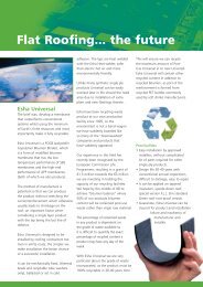

![Latexfalt® [HD] - Lane Roofing](https://img.yumpu.com/28305785/1/184x260/latexfaltar-hd-lane-roofing.jpg?quality=85)