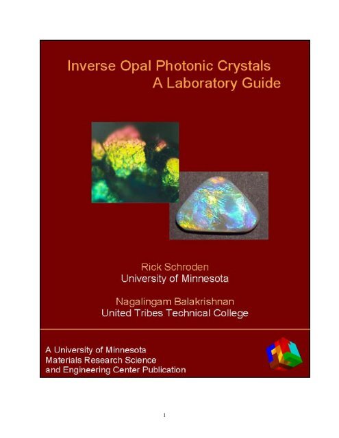
Inverse Opal Photonic Crystals - Department of Chemistry ...
Inverse Opal Photonic Crystals - Department of Chemistry ...
Inverse Opal Photonic Crystals - Department of Chemistry ...

Create successful ePaper yourself
Turn your PDF publications into a flip-book with our unique Google optimized e-Paper software.
<strong>Inverse</strong> <strong>Opal</strong> <strong>Photonic</strong> <strong>Crystals</strong><br />
A Laboratory Guide<br />
Authors<br />
Rick C. Schroden<br />
Nagalingam Balakrishnan<br />
Contributing Authors<br />
Andreas Stein<br />
Michael D. Ward<br />
University <strong>of</strong> Minnesota<br />
National Science Foundation<br />
Materials Research Science and Engineering Center<br />
2
<strong>Inverse</strong> <strong>Opal</strong> <strong>Photonic</strong> <strong>Crystals</strong><br />
A Laboratory Guide<br />
A Publication <strong>of</strong> the University <strong>of</strong> Minnesota Materials Research Science and Engineering<br />
Center, developed with the support <strong>of</strong> the National Science Foundation<br />
Copyright 2001 by the University <strong>of</strong> Minnesota Materials Research Science and Engineering<br />
Center. All rights reserved. Except as permitted under the United States Copyright Act, no part<br />
<strong>of</strong> the publication may be reproduced or distributed in any form or by any means, or stored in a<br />
database or retrieval system, without prior written permission <strong>of</strong> the publisher.<br />
Send all inquiries to:<br />
Materials Research Science and Engineering Center<br />
University <strong>of</strong> Minnesota<br />
Amundson Hall 491<br />
421 Washington Ave. SE<br />
Minneapolis, MN 55455<br />
Email: mrsec@mrsec.umn.edu<br />
3
ABOUT THE AUTHORS<br />
Rick C. Schroden is a graduate student in the <strong>Chemistry</strong> <strong>Department</strong> at the University <strong>of</strong><br />
Minnesota, advised by Pr<strong>of</strong>essor Andreas Stein. He received his B.S. degree in <strong>Chemistry</strong> in<br />
1997 from St. Cloud State University. His research interests include the design and analysis <strong>of</strong><br />
porous materials for catalysis, optics, photonics, and sorption.<br />
Nagalingam Balakrishnan is a science and mathematics instructor at the United Tribes<br />
Technical College in Bismarck, North Dakota. He earned his B. Sc. degree in <strong>Chemistry</strong> and<br />
Mathematics in 1983 from the University <strong>of</strong> Jaffna, Sri Lanka and his Ph.D. in <strong>Chemistry</strong> in<br />
1992 from North Dakota State University. Dr. Balakrishnan currently teaches a range <strong>of</strong> courses<br />
at United Tribes, including chemistry, physical science, algebra, and precalculus. He has been<br />
the recipient <strong>of</strong> National Science Foundation grants for math and science enrichment in the<br />
American Indian Community.<br />
Contributing Authors<br />
Andreas Stein is an Associate Pr<strong>of</strong>essor <strong>of</strong> <strong>Chemistry</strong> at the University <strong>of</strong> Minnesota. He<br />
received his B.Sc. in <strong>Chemistry</strong> in 1986 from the University <strong>of</strong> Calgary and his Ph.D. in Physical<br />
chemistry in 1991 from the University <strong>of</strong> Toronto. His research group focuses on controlling the<br />
composition, architecture and surface properties <strong>of</strong> inorganic and hybrid porous materials.<br />
Michael D. Ward is a Pr<strong>of</strong>essor <strong>of</strong> Chemical Engineering and Materials Science at the<br />
University <strong>of</strong> Minnesota and the Director <strong>of</strong> the University <strong>of</strong> Minnesota Materials Research<br />
Science and Engineering Center. He received his B.Sc. in <strong>Chemistry</strong> in 1977 from the William<br />
Paterson College <strong>of</strong> New Jersey and his Ph.D. in <strong>Chemistry</strong> in 1981 from the Princeton<br />
University. His research interests revolve around crystal growth and design.<br />
4
FOREWARD<br />
This laboratory guide was conceived during the summer <strong>of</strong> Y2001 at the University <strong>of</strong><br />
Minnesota Materials Research Science and Engineering Center (UMN MRSEC) by Nagalingam<br />
Balakrishnan, a faculty member <strong>of</strong> the United Tribes Technical College who participated in the<br />
UMN MRSEC summer research program with his student Anna Gopher. This team worked in<br />
the research group <strong>of</strong> Pr<strong>of</strong>essor Andreas Stein in the <strong>Department</strong> <strong>of</strong> <strong>Chemistry</strong> <strong>of</strong> UMN, studying<br />
the synthesis <strong>of</strong> “inverse opals,” wherein uniformly sized polymer spheres are used as templates<br />
for sol-gel condensation reactions to produce inorganic solid replicas with uniformly spaced<br />
macropores. These materials are particularly intriguing because the uniform spacing <strong>of</strong> the<br />
macropores and the large periodicities result in peculiar optical properties that prevent the<br />
transmission <strong>of</strong> specific wavelengths <strong>of</strong> light. They are crystals in every sense <strong>of</strong> the word, but<br />
with the crystal lattice defined by the macropores. One glance at these crystals reveals light<br />
refraction identical to that observed in natural opals, which are simply crystals <strong>of</strong> uniformly<br />
spaced silica spheres. This laboratory guide has been prepared with the intention <strong>of</strong> teaching<br />
specific laboratory techniques – emulsion polymerization, templated sol-gel condensation,<br />
sintering, and optical measurements – to undergraduate students, and possibly high school<br />
students. We believe that the deep appreciation <strong>of</strong> jewelry and other artifacts, including opals,<br />
by Native American communities makes this a particularly attractive laboratory module for<br />
science instruction in tribal colleges.<br />
Special thanks are due Dr. Frank Snowden, the Associate Direction <strong>of</strong> the UMN Education and<br />
Human Resources program, for his coordination <strong>of</strong> the outreach activities that led to this guide.<br />
This guide would not have been possible without the generous support <strong>of</strong> the National Science<br />
Foundation, which provided funding for the UMN MRSEC and its summer research programs<br />
for external participants.<br />
Michael D. Ward<br />
Director, UMN MRSEC<br />
5
Table <strong>of</strong> Contents<br />
1. Overview ……………………………………………………………….… 1<br />
A. <strong>Opal</strong>s ……………………………………………………….…….….… 1<br />
B. Polymerization ………………………………………….………...…… 2<br />
C. Sol-gel chemistry ……………………………………….………….….. 5<br />
D. <strong>Inverse</strong> opals ……………………………………………..………....…. 6<br />
2. Equipment, chemicals, and setup ………………………………………... 8<br />
A. Equipment needed for emulsion polymerization ……………………… 8<br />
B. Preliminary equipment setup for emulsion polymerization ………...… 10<br />
C. Chemicals needed for emulsion polymerization ………………………. 13<br />
D. Equipment needed for sol-gel templating ……………….…………….. 14<br />
E. Chemicals needed for sol-gel templating ……………………………… 15<br />
3. Making the polymer sphere templates …………………….…………..… 15<br />
A. Experiment overview …………………………………………..…..…. 15<br />
B. Emulsion polymerization procedure …………………………….....….. 18<br />
C. Cleanup <strong>of</strong> polymerization apparatus …………………………….…… 20<br />
D. Packing the spheres into a colloidal crystal …………………………… 20<br />
4. Making the inverse opals by sol-gel templating …………………..……. 21<br />
A. Experiment overview ………………………………………………..… 21<br />
B. Sol-gel templating procedure …………………………………….…..… 23<br />
C. Removing the polymer sphere template ………………………………. 25<br />
5. Optical properties <strong>of</strong> inverse opals ……………………………………… 25<br />
A. Viewing the colors <strong>of</strong> inverse opals ……………………………….….. 25<br />
B. Predicting and changing the colors <strong>of</strong> inverse opals ……………….…. 28<br />
6. Additional compositions <strong>of</strong> inverse opals …………………………….… 30<br />
7. Appendix …………………………………………………….….….…..…. 32<br />
A. Manifest for emulsion polymerization equipment ……….………….… 32<br />
B. Manifest for sol-gel templating equipment …………………….….….. 33<br />
C. Manifest for chemicals ……………………………………………….... 33<br />
8. Acknowledgment …………………………………………………......…... 33<br />
9. References ……………………………………………………………..….. 34<br />
6
Overview<br />
This laboratory manual is designed to guide instructors and students in the preparation <strong>of</strong> inverse<br />
opal materials from beginning to end, including setup <strong>of</strong> equipment, preparation <strong>of</strong> polymer<br />
sphere templates, sol-gel templating to produce inverse opals, and study <strong>of</strong> optical properties.<br />
The best practices for successful results are given for each step, along with ordering information<br />
for specialized equipment. This lab exercise is recommended as a three-part experiment: Week 1<br />
- synthesize the polymer sphere templates; Week 2 - synthesize the inverse opals; Week 3 -<br />
explore the optical properties. Alternatively, the lab exercise can be organized as a two-part<br />
experiment if the polymer templates are prepared in advance by either a student group or the<br />
instructor.<br />
1. Introduction<br />
A. <strong>Opal</strong>s<br />
<strong>Opal</strong>s are among the most colorful <strong>of</strong><br />
all gems despite being composed<br />
primarily <strong>of</strong> silica, a colorless solid<br />
with the chemical formula SiO 2 (opals<br />
have the same chemical composition<br />
as window glass and quartz). Their<br />
name comes from the Latin word<br />
opalus meaning “to see a change <strong>of</strong><br />
color.” They exhibit a play <strong>of</strong> color<br />
(<strong>of</strong>ten called opalescence), which<br />
consists <strong>of</strong> iridescent color flashes that<br />
Figure 1. Photographs <strong>of</strong> opals displaying rainbows <strong>of</strong> colors<br />
that change as the angle <strong>of</strong> observation changes.<br />
change with the angle at which they are viewed (Figure 1). The effect is similar to the rainbow<br />
<strong>of</strong> colors observed on a soap bubble, only much more dramatic. The origin <strong>of</strong> iridescence in<br />
opals comes from an ordered microstructure <strong>of</strong> closely packed silica spheres, which causes light<br />
to diffract from the planes <strong>of</strong> spheres. Since the size <strong>of</strong> these silica spheres is on the order <strong>of</strong><br />
hundreds <strong>of</strong> nanometers, the wavelength <strong>of</strong> the diffracted light is also on the order <strong>of</strong> hundreds <strong>of</strong><br />
nanometers. This range <strong>of</strong> wavelengths falls within the visible region <strong>of</strong> light, spanning<br />
approximately 380 to 750 nanometers. Visible wavelengths are those that can be detected by our<br />
eyes, and they cover only a small portion <strong>of</strong> the electromagnetic spectrum, which also includes<br />
gamma-rays, X-rays, ultraviolet, infrared, microwaves, and radio waves (Figure 2).<br />
Diffraction <strong>of</strong> light from opals can cause flashes <strong>of</strong> any color <strong>of</strong> the rainbow, with the diameter<br />
and spacing <strong>of</strong> the silica spheres affecting the observed color. <strong>Opal</strong>s made <strong>of</strong> smaller spheres<br />
tend to display the violets and blues (which have shorter wavelengths), while those made <strong>of</strong><br />
larger spheres tend to display the reds (which have longer wavelengths). The more uniform the<br />
silica spheres with respect to size and arrangement, the more intense and defined the color.<br />
7
Figure 2. Classification <strong>of</strong> the wavelengths <strong>of</strong> radiation in the electromagnetic spectrum. The small range <strong>of</strong><br />
wavelengths that can be detected by our sense <strong>of</strong> sight is called visible light. The bar at the bottom illustrates an<br />
approximate distribution <strong>of</strong> visible wavelengths.<br />
B. Polymerization<br />
A polymer is a large molecule consisting <strong>of</strong> many repeating chemical units, called monomers.<br />
Polymers are formed by the process <strong>of</strong> polymerization, in which many monomer molecules react<br />
to form very large molecules. Polymers generally are formed in two ways: step-growth<br />
polymerization or chain-growth polymerization. Step-growth polymerization involves the<br />
stepwise addition <strong>of</strong> monomers with two functional groups. Each reaction is essentially<br />
independent <strong>of</strong> the preceding one, and a polymer is formed simply because the monomers<br />
undergo reactions at more than one functional group. This makes step-growth formation <strong>of</strong> high<br />
molecular weight polymers difficult, and requires high-yield reactions to produce large<br />
polymers. By comparison, chain-growth polymerization involves the sequential addition <strong>of</strong><br />
monomers to the end <strong>of</strong> an active polymer chain. In each case a reactive particle (such as a free<br />
radical, cation, or anion) produces another reactive particle, preserving the reactivity <strong>of</strong> the<br />
chain. As a result, chain-growth polymerizations allow the rapid preparation <strong>of</strong> very high<br />
molecular weight polymers.<br />
The first part <strong>of</strong> the lab exercise involves the preparation <strong>of</strong> poly(methyl methacrylate) (PMMA)<br />
by a free radical chain-growth polymerization. PMMA is sold commercially under familiar trade<br />
names such as Plexiglas ® and Lucite ® . In this lab procedure, uniformly sized PMMA spheres<br />
will be prepared by the polymerization <strong>of</strong> methyl methacrylate (MMA) in water. Since MMA<br />
(which is an oily liquid) is not soluble in water, it must by polymerized by a process referred to<br />
as emulsion polymerization. An emulsion is a suspension <strong>of</strong> oil drops in water.<br />
There are three stages in chain-growth polymerizations: initiation, propagation, and termination.<br />
These stages are illustrated in Figure 3 for the synthesis <strong>of</strong> PMMA that will be performed in this<br />
lab exercise. To begin the polymerization it is necessary to have an initiator, which is a molecule<br />
capable <strong>of</strong> forming a reactive particle. Azo-compounds, which decompose upon heating to<br />
produce two organic radicals and nitrogen gas, are commonly used initiators. The initiator used<br />
in this experiment is the azo-initiator 2,2'-azobis(2-methylpropionamidine).<br />
In the initiation stage <strong>of</strong> this polymerization (Figure 3), thermal decomposition <strong>of</strong> the azoinitiator<br />
generates two free radicals, which subsequently add to the double bond <strong>of</strong> the MMA<br />
monomer. Once initiated, successive additions <strong>of</strong> MMA monomers to the free radical end <strong>of</strong> the<br />
polymer chain causes the chain to grow (propagation stage). In each step, the consumption <strong>of</strong> a<br />
8
free radical is accompanied by the formation <strong>of</strong> a new, larger free radical. Eventually, in the<br />
termination stage, the polymerization stops by steps that consume, but do not form, free radicals,<br />
such as the combination <strong>of</strong> two free radicals.<br />
Figure 3. Free radical chain-growth polymerization <strong>of</strong> MMA using the azo-initiator 2,2'-azobis(2-<br />
methylpropionamidine) to produce PMMA. Initiation: The initiator decomposes upon heating to form free radicals,<br />
which attack the double bonds <strong>of</strong> MMA, forming larger free radicals. Propagation: Successive additions <strong>of</strong> MMA<br />
monomers increase the polymer size. Termination: Growth ceases when two radicals react. The initiator is<br />
incorporated into the polymer, forming amine end groups.<br />
The product <strong>of</strong> the polymerization performed in this lab initially takes the form <strong>of</strong> a colloidal<br />
suspension <strong>of</strong> solid particles that are so small that they tend not to settle. With careful control <strong>of</strong><br />
reaction conditions, the PMMA forms uniformly sized spherical particles. 1 By centrifuging, the<br />
PMMA particles can be forced to settle and pack into a solid, called a colloidal crystal. In this<br />
colloidal crystal, the PMMA spheres are arranged in a close-packed fashion in the same manner<br />
as the silica spheres that make up natural opals. These materials can, therefore, be referred to as<br />
synthetic opals. A scanning electron micrograph (SEM) <strong>of</strong> a PMMA colloidal crystal (synthetic<br />
opal) is illustrated in Figure 4.<br />
9
Figure 4. SEM <strong>of</strong> a PMMA colloidal crystal illustrating the close-packed layers <strong>of</strong> PMMA spheres. Spheres<br />
typically pack in a face-centered cubic structure, wherein each sphere contacts 12 others (6 in the same layer, 3 in<br />
the layer above, and 3 in the layer below).<br />
C. Sol-gel chemistry<br />
The second part <strong>of</strong> the lab exercise involves the formation <strong>of</strong> a solid structure around the PMMA<br />
colloidal crystals by the process <strong>of</strong> sol-gel chemistry. 2 In the system here, a sol is a solution <strong>of</strong><br />
polymerizable metallo-organic species. A gel is a continuous solid network (a very large<br />
molecule) surrounding and supporting a continuous liquid phase. In the sol-gel process, network<br />
solids are formed by the reactions <strong>of</strong> hydrolysis and condensation. These reactions are illustrated<br />
in Figure 5 for tetramethoxysilane (TMOS), Si(OCH 3 ) 4 , which is the chemical used in this lab<br />
exercise for the preparation <strong>of</strong> silica (SiO 2 ). In the hydrolysis step, TMOS reacts with water,<br />
resulting in the replacement <strong>of</strong> an alkoxy group (-OCH 3 ) by a hydroxyl group (-OH) and the<br />
liberation <strong>of</strong> methanol (CH 3 OH). Because methanol can be somewhat toxic, tetraethoxysilane,<br />
TEOS, is actually a preferred starting material (the product is ethanol). Condensation reactions,<br />
which lead to growth <strong>of</strong> the network solid, occur between a hydroxyl group and an alkoxy group<br />
(alcoxolation), or two hydroxyl groups (oxolation), liberating methanol and water in the process.<br />
As this growth process continues, a sol <strong>of</strong> small chains or branched structures form. These<br />
chains continue to grow, and they eventually gel to form a continuous network solid, at which<br />
point the material changes from liquid to solid. The sol-gel process is complete upon removal <strong>of</strong><br />
the solvent and the organic products generated from the sol-gel reaction.<br />
Figure 5. Hydrolysis and condensation <strong>of</strong> tetramethoxysilane to form silica. The three bars connected to the Si<br />
atoms in the condensation steps represent bonds to three other hydroxyl (-OH) or alkoxy (-OCH 3 ) groups.<br />
10
D. <strong>Inverse</strong> opals<br />
The second part <strong>of</strong> the lab exercise also involves the creation <strong>of</strong> inverse opals, which are inverse<br />
replicas <strong>of</strong> opals. Instead <strong>of</strong> consisting <strong>of</strong> a regular arrangement <strong>of</strong> uniform spherical particles<br />
(as in opals), inverse opals consist <strong>of</strong> a regular arrangement <strong>of</strong> spherical void spaces surrounded<br />
by solid walls. The inverse opals are made after solidification <strong>of</strong> the sol in the void spaces <strong>of</strong> the<br />
synthetic PMMA opals (as described above), by removing the PMMA template to leave a threedimensionally<br />
ordered porous solid. 3,4 An SEM image <strong>of</strong> inverse opal silica is given in Figure 6.<br />
Figure 6. A scanning electron microscopy image <strong>of</strong> inverse opal silica illustrating a close-packed arrangement <strong>of</strong><br />
pores. The white regions are walls around the top layer <strong>of</strong> pores, the gray regions are walls around the second layer<br />
<strong>of</strong> pores, and the black regions are windows connecting the pores.<br />
In addition to the silica inverse opals made in this lab exercise, many other compositions <strong>of</strong><br />
inverse opals can be made, including metal oxides, metals, semiconductors, and others. 5 The<br />
motivation for making inverse opals includes their use in catalysis, sorption, chromatography,<br />
battery materials, and as bioactive materials – uses that benefit from the highly accessible<br />
surfaces and relatively large pore sizes <strong>of</strong> these materials. 5 In addition, the ordered arrangement<br />
<strong>of</strong> the pore structure leads to diffraction <strong>of</strong> light in a manner similar to the diffraction observed<br />
with opals. These diffraction effects endow inverse opals with optical and photonic crystal<br />
properties that may be utilized for optical sensors and circuits, and to guide light waves.<br />
The term “photonic crystal” is used to describe a material with a uniform repetition <strong>of</strong> low and<br />
high refractive index areas. 6,7 <strong>Inverse</strong> opals fit this definition, as they have a uniform<br />
arrangement <strong>of</strong> void spaces containing air (with a low refractive index <strong>of</strong> 1.000) and solid walls<br />
(with a higher refractive index, e.g. 1.455 for silica). A peculiar property <strong>of</strong> these materials is<br />
their ability to “filter” light. When white light, which contains all visible colors <strong>of</strong> light, is<br />
shined on a photonic crystal, some wavelengths are forbidden from passing through the material,<br />
being reflected instead (Figure 7). The remaining wavelengths are unaffected by the photonic<br />
crystal, and they simply pass through. For complete reflection, the refractive index <strong>of</strong> the wall<br />
material must exceed a value <strong>of</strong> 2.8. Significant reflection can be observed, however, even for<br />
lower values <strong>of</strong> the refractive index.<br />
11
Figure 7. Interaction <strong>of</strong> white light (which contains all visible colors) with an inverse opal photonic crystal. When<br />
white light impinges upon a photonic crystal, a range <strong>of</strong> light wavelengths is reflected, while the remaining light is<br />
transmitted.<br />
2. Equipment, chemicals, and setup<br />
A. Equipment needed for emulsion polymerization<br />
1. Round-bottom flask (5 neck, 3 L), with rubber or glass stopper<br />
2. Funnel<br />
3. Cylindrical heating mantle (3L)<br />
4. Temperature controller (Barnant Company)<br />
5. Thermocouple probe (Type K, 1/16"), used with an NMR tube, one-hole stopper, and<br />
parafilm<br />
6. Support stand (36") with three-finger clamp and clamp holder (for condenser) and clamp<br />
holder (for stirrer)<br />
7. Water-cooled condenser, with rubber tubing (three, about 4' each), small hose clamps (two),<br />
one-hole stopper, glass tubing (4"), glass pipette (disposable), Erlenmeyer flask (300 mL, for<br />
bubbler), and parafilm<br />
8. Electric lab stirrer, with thick rubber hose (3" long, 10 mm i.d., 23 mm o.d.), hose clamps<br />
(two), and high-temperature tape<br />
9. Glass stirring shaft (10 mm diameter, 58 cm long)<br />
10. Teflon stirrer blade for glass stirring shaft (1.9 cm wide, 7.6 cm long)<br />
11. Bearing and adapter set for glass stirring shaft<br />
12. Nitrogen gas cylinder (or house N 2 gas), with rubber tubing (3'), one-hole stopper, and glass<br />
pipette (disposable)<br />
13. Graduated cylinders (100 and 500 mL)<br />
14. Electric balance and weighing paper<br />
15. Metal spatula<br />
16. Screw driver (for hose clamps)<br />
17. Insulated gloves (for handling the hot reaction flask)<br />
18. Cork ring (stand for cooling round-bottom flask)<br />
19. Glass wool<br />
20. Plastic container (4 L) with cover<br />
21. Centrifuge (Fisher Marathon Model 8K)<br />
22. Bucket rotor for centrifuge<br />
23. Round centrifuge buckets (four)<br />
24. Round-bottom glass centrifuge tubes (four, 100 mL each) and Parafilm<br />
12
25. Small beakers (to hold the tubes upright during PMMA drying)<br />
26. Glass slides – optional (for testing the opalescence <strong>of</strong> the PMMA)<br />
27. Ordering information for the specialized items listed above can be found in the Appendix.<br />
These items, including the heating and stirring apparatuses, are the recommended (i.e., best<br />
practices) equipment for this procedure. Due to the sensitivity <strong>of</strong> PMMA sphere size to the<br />
polymerization reaction conditions, it is necessary to have strict control <strong>of</strong> the heating and<br />
stirring to produce uniform polymer spheres. If the temperature is carefully regulated,<br />
however, a simple oil or water bath, and a thermometer inserted through a one-hole stopper<br />
into the reaction flask, may be used instead <strong>of</strong> the cylindrical heating mantle, temperature<br />
controller, and thermocouple probe. Any electric lab stirrer (with speeds <strong>of</strong> 300-400 rpm)<br />
with a shaft and stirrer blade may be used, but the bearing and adapter set are necessary to<br />
maintain a sealed system. Any model centrifuge (with rotor, buckets, and tubes) with speeds<br />
<strong>of</strong> 1000-2000 rpm can be used.<br />
B. Preliminary equipment setup for emulsion polymerization<br />
The apparatus for the preparation <strong>of</strong> monodisperse PMMA spheres by emulsion polymerization<br />
is illustrated in Figure 8. Due to the complexity and time-consuming nature <strong>of</strong> this setup,<br />
instructor assembly <strong>of</strong> the polymerization apparatus prior to the lab period is highly<br />
recommended. Some <strong>of</strong> the following steps may not apply to research labs where pre-existing<br />
equipment is in place, so the instructions may be adapted to fit the individual laboratory and<br />
available equipment.<br />
1. In a ventilated hood, set the cylindrical heating mantle on the base <strong>of</strong> a support stand. Place<br />
the temperature controller beside the heating mantle, then plug the mantle and the<br />
thermocouple into the back <strong>of</strong> the temperature controller. Carefully insert an NMR tube into<br />
a one-hole stopper with the open end on top. Caution: Never push a glass tube by the end.<br />
Instead, hold it near the stopper opening, and insert by wetting with a small amount <strong>of</strong> water<br />
and slowly turning the tube. Holding the NMR tube in the rubber stopper upright, fill it with<br />
water, then thread the thermocouple wire into the tube until it touches the bottom. Seal the<br />
NMR tube shut with Parafilm. This arrangement allows the temperature <strong>of</strong> the emulsion<br />
polymerization reaction to be monitored in the round-bottom flask by the thermocouple wire<br />
while maintaining a sealed system with the stopper.<br />
2. Attach a water-cooled condenser to the support stand using a three-finger clamp and a clamp<br />
holder. Fasten two rubber tubes (<strong>of</strong> appropriate length to reach a faucet and drain) to the<br />
condenser using hose clamps. Attach the free end <strong>of</strong> the bottom tube to the cold-water faucet<br />
and place the free end <strong>of</strong> the top tube into the drain. Insert a glass tube about 4 inches in<br />
length carefully into a one-hole stopper. Place this stopper into the top <strong>of</strong> the condenser.<br />
Attach one end <strong>of</strong> a third rubber tube to the end <strong>of</strong> the glass tube. Insert a disposable glass<br />
pipette into the opposite end <strong>of</strong> this tube, and place the pipette into a 300 mL Erlenmeyer<br />
flask filled with water. Wrap the top <strong>of</strong> the flask loosely with Parafilm to hold the tube and<br />
pipette in place. This bubbler arrangement will prevent a back-flow <strong>of</strong> room air into the flask<br />
during the reaction, assuring the system will be under a positive pressure <strong>of</strong> Nitrogen gas.<br />
13
3. Insert a disposable glass pipette into a one-hole stopper. Attach one end <strong>of</strong> a rubber hose to<br />
the pipette and the other end to a nitrogen line. Ensure that the glass pipette is sufficiently<br />
long to be submerged during the emulsion polymerization procedure to allow nitrogen to<br />
bubble into the liquid. This prevents the formation <strong>of</strong> oxygen free radicals, which would<br />
inhibit polymer growth.<br />
4. Mount the electric lab stirrer onto the support stand using a clamp holder. Wrap a few<br />
rounds <strong>of</strong> high-temperature tape around the metal stirrer shaft. Cut out a 3-inch length <strong>of</strong><br />
thick rubber hose (10 mm inner diameter, 23 mm outer diameter). Attach the hose to the<br />
metal stirrer shaft and secure it with a hose clamp. Place another hose clamp on the other<br />
end <strong>of</strong> the hose for later attachment <strong>of</strong> the glass stirring shaft.<br />
5. Using Figure 9 as a guide, assemble the bearing and adapter set. Insert the Teflon inner<br />
bearing into the threaded glass adapter, followed by the compression saddle and o-ring.<br />
Screw the bushing into the glass adapter until snug, then tighten the lock nut. Place the<br />
Teflon stirrer blade on the glass stirring shaft. Slip the bearing and adapter set over the glass<br />
stirring shaft. Insert the stirring apparatus into the central neck <strong>of</strong> the round-bottom flask.<br />
Make sure that the stir blade remains upright. It may be necessary to insert a spatula or wire<br />
into another neck <strong>of</strong> the flask to flip the blade upright. Keep the stir blade about one inch<br />
from the bottom (close enough to the bottom so that the stir blade cannot flip over). Lower<br />
the electric stirrer and insert the top <strong>of</strong> the glass stirring shaft into the hose affixed to the<br />
electric stirrer. Secure the shaft to the hose by tightening the hose clamp.<br />
14
Figure 8. Emulsion polymerization apparatus. The stirring assembly is inserted in the central neck <strong>of</strong> the 5-neck<br />
round-bottom flask. Three other necks are used to attach a nitrogen line, thermocouple probe, and water-cooled<br />
condenser. The remaining neck is used for the addition <strong>of</strong> reagents, and is covered by a stopper during the reaction.<br />
15
Figure 9. Left: Assembly <strong>of</strong> the bearing and adapter set. Right: Assembly <strong>of</strong> the stirring apparatus.<br />
C. Chemicals needed for emulsion polymerization<br />
1. Methyl methacrylate (MMA), (300-400 mL)<br />
2. 2,2'-Azobis(2-methylpropionamidine) dihydrochloride (1.5 g)<br />
3. Distilled, deionized water (1600 mL)<br />
4. Tetrahydr<strong>of</strong>uran (THF), (for cleanup)<br />
5. Acetone, (for cleanup)<br />
Ordering information for the chemicals can be found in the Appendix. Use care in the handling<br />
<strong>of</strong> all chemicals and observe safe lab practices. Wear goggles, gloves, and a lab coat. Perform<br />
all experiments in a ventilated hood. MMA has a strong odor and may be harmful by inhalation<br />
or skin absorption; avoid prolonged or repeated exposure and don’t breathe the vapor. MMA is a<br />
flammable liquid; keep away from all sources <strong>of</strong> ignition. THF and acetone are harmful and<br />
extremely flammable liquids; prevent contact and keep away from ignition sources.<br />
D. Equipment needed for sol-gel templating<br />
1. Electric stir plate<br />
2. Small glass vials (20 mL)<br />
3. Magnetic stir bar (3/8”)<br />
4. Filtering flask, used with rubber tubing and vacuum line<br />
5. Neoprene adapter<br />
6. Büchner funnel with filter paper<br />
7. Drying dish (small plastic dish to hold the samples while drying)<br />
8. Disposable glass pipettes with bulbs<br />
9. Metal spatula<br />
16
10. Graduated cylinder (10 mL)<br />
11. Programmable muffle furnace, equipped with an injection port kit (a<br />
standard furnace can be used with manual operation; see text)<br />
12. Porcelain crucibles<br />
13. Glass microscope slides (to observe the opalescence <strong>of</strong> the samples)<br />
14. Microscope – optional (to observe the opalescence <strong>of</strong> the samples)<br />
The equipment listed above are the preferred items for this procedure, however, not all <strong>of</strong> them<br />
are required. The electric stir plate and magnetic stir bar are used to mix the sol-gel reagents<br />
prior to templating. Alternatively, adding the reagents one at a time to a vial and drawing the<br />
fluid in and out <strong>of</strong> a glass pipette will mix the reagents adequately. This procedure generally<br />
works better than stirring with a glass rod. A programmable muffle furnace is preferred for<br />
reasons <strong>of</strong> safety and product quality. Controlled heating ramps prevent ignition and rapid<br />
burning <strong>of</strong> the samples, avoiding a potential fire hazard. In addition, slow heating ramps allow<br />
the inverse opal walls to uniformly condense while the PMMA slowly burns away, producing<br />
well-ordered samples. If a programmable furnace is not available, a standard furnace can be<br />
used, but only for the silica inverse opals. In this case, the temperature should be raised manually<br />
in 50 o increments, with 30 minutes spent at each intermediate temperature (the 10 hour hold at<br />
600 o C is still required). Büchner funnels are recommended over glass-frit funnels, which will<br />
become clogged and difficult to clean in this procedure. Ordering information for the specialized<br />
items listed above can be found in the Appendix.<br />
E. Chemicals needed for sol-gel templating<br />
1. PMMA spheres (prepared in the first part <strong>of</strong> this lab), (10 g)<br />
2. Tetramethoxysilane (TMOS) or tetraethoxysilane (TEOS), (6 mL)<br />
3. Methanol or ethanol (4 mL)<br />
4. Distilled, deionized water (3 mL)<br />
5. Concentrated hydrochloric acid (HCl), (1 mL)<br />
Ordering information for the chemicals can be found in the Appendix. Use care in the handling<br />
<strong>of</strong> all chemicals and observe safe lab practices. Wear goggles, gloves, and a lab coat. Perform<br />
all experiments in a ventilated hood. TMOS and methanol are interchangeable with TEOS and<br />
ethanol, but for reasons <strong>of</strong> safety (lower toxicity) the TEOS/ethanol combination is preferred.<br />
TMOS and TEOS are harmful if swallowed, inhaled, or absorbed through skin, and are highly<br />
flammable. Do not breathe the vapor, prevent contact with skin and eyes, and avoid sources <strong>of</strong><br />
ignition. Methanol and ethanol are harmful and extremely flammable. Prevent contact with skin<br />
and eyes, do not breathe the vapor, and avoid all sources <strong>of</strong> ignition. Hydrochloric acid (HCl)<br />
can cause severe burns, and its vapor is extremely irritating; prevent contact with skin and eyes,<br />
do not inhale, and always use in a hood.<br />
3. Making the polymer sphere templates<br />
A. Experiment overview<br />
Before inverse opals can be synthesized, it is necessary to prepare the PMMA sphere colloidal<br />
crystal templates. Due to the complexity <strong>of</strong> the emulsion polymerization apparatus, it is<br />
recommended that the polymer spheres be produced in large batches by the instructor or by<br />
17
teams <strong>of</strong> students. The size <strong>of</strong> the polymer spheres directly affects the pore size <strong>of</strong> the inverse<br />
opals, which in turn affects the color <strong>of</strong> light reflected by the inverse opals. It is recommended<br />
that each group prepares a different size batch <strong>of</strong> spheres (if multiple batches are prepared) or the<br />
instructor prepares different sizes <strong>of</strong> PMMA spheres prior to the lab period. This will allow for<br />
comparisons <strong>of</strong> the optical properties <strong>of</strong> the products to be made.<br />
The entire process - from the synthesis <strong>of</strong> a colloidal suspension <strong>of</strong> PMMA through the<br />
attainment <strong>of</strong> ready-to-use PMMA template spheres - takes roughly one week (Figure 10). We<br />
recommend assembly <strong>of</strong> the complex components <strong>of</strong> the polymer apparatus by the instructor<br />
prior to the laboratory period (detailed in Figure 8 and the discussion above). The emulsion<br />
polymerization procedure requires the heating <strong>of</strong> a large quantity <strong>of</strong> water and methyl<br />
methacrylate (MMA) to 70 or 80 °C, which may require up to two hours. The instructor may<br />
choose to begin heating the mixture before the lab period begins to save time. Follow-up<br />
centrifuging and water decanting is also required. It is left up to the instructor’s discretion<br />
whether to handle these follow-up procedures, or to designate students to carryout these steps.<br />
Table 1 provides a good guideline to follow in the preparation <strong>of</strong> PMMA spheres. Templating<br />
with these three sphere sizes will produce inverse opals with distinctly different reflected colors.<br />
The parameters may be adjusted to produce PMMA spheres <strong>of</strong> intermediate sizes. To make<br />
larger spheres, use more MMA (while keeping the amount <strong>of</strong> water constant), use a lower<br />
temperature, or use less initiator. To make smaller spheres, use less MMA, use a higher<br />
temperature, or use more initiator. We recommend following the recipes in Table 1 as these<br />
PMMA sizes will produce inverse opals with light reflections in the visible region. Spheres <strong>of</strong><br />
smaller or larger sizes will lead to products without visible reflections.<br />
Using the parameters in Table 1 will lead to inverse opal silica materials that appear blue-violet,<br />
green, and orange-pink in reflected light for the small, medium, and large PMMA-templated<br />
products, respectively. Each preparation will yield in excess <strong>of</strong> 250 grams <strong>of</strong> PMMA.<br />
Quantities may be scaled-down as appropriate to fit the class size. Use care in the handling <strong>of</strong> all<br />
chemicals and observe safe lab practices. Wear goggles, gloves, and a lab coat during this<br />
experiment. Perform all experiments in a ventilated hood.<br />
18
Figure 10. Schematic <strong>of</strong> the preparation <strong>of</strong> PMMA spheres by emulsion polymerization and the formation <strong>of</strong><br />
colloidal crystals by centrifuging. A sign <strong>of</strong> a successful polymerization is bright opalescence <strong>of</strong> the PMMA<br />
colloidal crystal pellet.<br />
Table 1. Recommended parameters for the preparation <strong>of</strong> PMMA spheres. The small, medium, and large<br />
designations refer to the PMMA sphere diameters, and to the pore sizes <strong>of</strong> the inverse opals produced by these<br />
spheres. These are arbitrary designations, made only for comparison purposes and ease <strong>of</strong> discussion.<br />
Sample Approximate<br />
diameter<br />
Water<br />
volume<br />
MMA<br />
volume<br />
Temp. Initiator<br />
mass<br />
Small 310 nm 1.6 L 300 mL 80 °C 1.5 g<br />
Medium 375 nm 1.6 L 300 mL 70 °C 1.5 g<br />
Large 425 nm 1.6 L 400 mL 70 °C 1.5 g<br />
B. Emulsion polymerization procedure<br />
1. Using Figure 8 as a guide, place the 5-neck round-bottom flask into the cylindrical heating<br />
mantle and insert the stirrer assembly, nitrogen line, water-cooled condenser, and<br />
thermocouple probe into the necks <strong>of</strong> the flask. Make sure that the stirrer blade is upright.<br />
2. Insert a funnel into the open neck <strong>of</strong> the flask for the addition <strong>of</strong> reagents. Using a graduated<br />
cylinder, measure out 1.6 L <strong>of</strong> distilled, deionized water and pour it into the reaction flask.<br />
Select your choice <strong>of</strong> PMMA size from Table 1 and add the appropriate quantity <strong>of</strong> MMA to<br />
the flask. Remove the funnel and insert a rubber or glass stopper into this neck.<br />
3. Turn on the nitrogen gas. The flow rate should be very slow (approximately 3-4 bubbles per<br />
second). The slow flow rate is necessary to prevent pressure build-up in the reaction flask.<br />
4. Turn on the water for the condenser. Again, only a very slow flow <strong>of</strong> water is needed.<br />
19
5. Turn on the electric stirrer to a speed <strong>of</strong> approximately 350 rpm, (this corresponds to a stir<br />
setting <strong>of</strong> about 2.5 for the model <strong>of</strong> stirrer listed in the Appendix).<br />
6. Using the arrows on the Temperature Controller, set the temperature to 70 or 80 o C<br />
(following Table 1 parameters for your choice <strong>of</strong> PMMA size), and press “Tune” (an<br />
indicator light will turn on). The reaction mixture will heat-up and stabilize at the chosen<br />
temperature, at which time the indicator light will turn <strong>of</strong>f. The temperature <strong>of</strong> the reaction<br />
mixture will appear on the screen <strong>of</strong> the Temperature Controller throughout the heating<br />
process. This process may require two hours if cold water was used in the synthesis. It is<br />
very important to the quality <strong>of</strong> the PMMA spheres produced for the temperature to have<br />
stabilized before continuing to the next step.<br />
7. When the temperature has stabilized at the desired level (70 or 80 o C), turn <strong>of</strong>f the nitrogen<br />
gas. Leave the nitrogen line and one-hole stopper in the flask.<br />
8. Place a piece <strong>of</strong> weighing paper on a balance, zero it, and weigh out 1.50 g <strong>of</strong> 2,2’-Azobis(2-<br />
methylpropionamidine) dihydrochloride initiator. Remove the stopper from the reaction<br />
flask, add the initiator, and replace the stopper. Within a few minutes, a white milky<br />
colloidal suspension will form. The synthesis will be complete within 1 to 1.5 hours. The<br />
temperature <strong>of</strong> the reaction mixture typically rises 5 to 10 o C over this period, and then<br />
decreases to the original temperature. This is perfectly normal and indicates the reaction is in<br />
progress. No manual adjustment <strong>of</strong> the temperature is needed, just leave the apparatus<br />
untouched.<br />
9. Turn <strong>of</strong>f the Temperature Controller after 1 hour if the temperature has stabilized at its initial<br />
value. If the temperature hasn’t stabilized after 1 hour, wait another 30 minutes before<br />
turning it <strong>of</strong>f. Remove the thermocouple probe and nitrogen line from the flask.<br />
10. Turn <strong>of</strong>f the Electric Stirrer. Raise the stirrer a few inches by adjusting the clamp holder up<br />
the support stand. Loosen the hose clamp on the rubber hose that attaches the glass stir shaft<br />
to the Electric Stirrer, and carefully pull the glass stir shaft down to detach it from the stirrer.<br />
11. Turn <strong>of</strong>f the water and raise the condenser out <strong>of</strong> the flask by loosening the three-finger<br />
clamp, lifting the condenser, then tightening the clamp.<br />
12. Wearing insulated gloves, very carefully lift the flask out <strong>of</strong> the cylindrical heating mantle<br />
and onto a cork ring (we recommend that the instructor handle hot reaction flasks). Allow<br />
the sample to cool for at least one hour.<br />
13. Insert a funnel into a large (4 L) plastic container. Place glass wool in the funnel. Slowly<br />
pour the PMMA suspension through the glass wool in the funnel (this will remove any large<br />
chunks <strong>of</strong> PMMA). A benchmark for a successful synthesis is opalescence <strong>of</strong> the sample. A<br />
good way to view this is to dip a spatula into the liquid and smear a little on a dark bench top.<br />
As it dries, a good sample will look colorful (Figure 11). You can also try dipping a glass<br />
slide into the liquid, then pulling it out. After it dries it will be opalescent, appearing<br />
different colors depending upon the angle <strong>of</strong> observation.<br />
20
Figure 11. Left: Photograph <strong>of</strong> a PMMA colloidal suspension smeared on a black bench top. A successful<br />
preparation will yield a sample that changes from a white milky liquid to a colorful iridescent powder upon drying.<br />
Right: Photograph <strong>of</strong> a dried PMMA colloidal suspension on a glass slide. A successful product will appear<br />
colored, and change colors with angle <strong>of</strong> observation.<br />
C. Cleanup <strong>of</strong> polymerization apparatus<br />
Clean the flask and stirring apparatus with water. If any PMMA remains stuck to the flask or<br />
stirrer (which is usually the case), the instructor should add a 50:50 mixture <strong>of</strong> THF and acetone<br />
to the flask, and heat at 50 o C for a few hours. This solvent mixture will dissolve any remaining<br />
polymer. Pour the solvents into a waste bottle when done, and rinse the flask and stirrer with<br />
acetone.<br />
D. Packing the spheres into a colloidal crystal<br />
1. Place the centrifuge tubes into their buckets, and fill the tubes with the colloidal PMMA<br />
suspension. Add the same amount to each tube to ensure the centrifuge will be balanced<br />
(placing samples with different weights into a centrifuge will cause it to shake vigorously).<br />
Cover the tubes with Parafilm. Place the buckets on the rotor in the centrifuge. Close the<br />
cover and set the rotation rate at about 1500 rpm. Start the centrifuge, and let the samples<br />
spin for one day.<br />
2. Stop the centrifuge, and remove the samples.<br />
You should see a clear liquid in the top portion<br />
<strong>of</strong> tubes, and a white solid at the bottom. If you<br />
don’t see this separation, the samples will<br />
require further centrifuging. Carefully decant<br />
(pour gently) the liquid into a waste bottle. Set<br />
the centrifuge tubes containing the PMMA<br />
colloidal suspensions upright in small beakers.<br />
Let the samples sit open for 3 to 4 days to dry.<br />
The samples are dry when the colloidal crystal<br />
pellets <strong>of</strong> PMMA easily come out <strong>of</strong> the tubes<br />
when tipped over. High quality PMMA will<br />
exhibit bright opalescence on the top surface <strong>of</strong><br />
the pellet (Figure 12).<br />
Figure 12. Photograph <strong>of</strong> the smooth top<br />
surface <strong>of</strong> a PMMA colloidal crystal pellet<br />
illuminated with white light. A benchmark<br />
<strong>of</strong> a successful polymerization is the<br />
appearance <strong>of</strong> opalescence with intense<br />
colors.<br />
21
4. Making the inverse opals by sol-gel templating<br />
A. Experiment overview<br />
In this portion <strong>of</strong> the lab exercise, the PMMA colloidal crystals prepared in the previous step are<br />
used to template the formation <strong>of</strong> inverse opals. This preparation involves the vacuum<br />
infiltration <strong>of</strong> PMMA spheres by a sol-gel precursor and removal <strong>of</strong> the template by calcination<br />
(which is heating to burn away the polymer, see Figure 13). The samples can be placed in the<br />
furnace, and the calcination process can be started during the lab period. The entire calcination<br />
requires roughly one day, so follow-up removal <strong>of</strong> the samples will be required (safety reminder:<br />
do not remove samples from the oven until they have cooled completely). Depending upon the<br />
number <strong>of</strong> samples and size <strong>of</strong> the furnace, some samples may have to be calcined on following<br />
days. It is left to the instructor’s discretion whether to handle these follow-up procedures, or to<br />
designate students to carryout this work. Use care in the handling <strong>of</strong> all chemicals and observe<br />
safe lab practices. Wear goggles, gloves, and a lab coat during this experiment. Perform all<br />
experiments in a ventilated hood.<br />
Figure 13. Schematic <strong>of</strong> the preparation <strong>of</strong> inverse opals by sol-gel templating (the sizes <strong>of</strong> the PMMA spheres are<br />
greatly exaggerated for illustration purposes). PMMA colloidal crystal templates are placed in a Büchner funnel,<br />
and then infiltrated with sol-gel precursors, dried, and heated at high temperatures to remove the PMMA and cure<br />
the walls <strong>of</strong> the inverse opal product.<br />
22
B. Sol-gel templating procedure<br />
1. Using Figure 13 as a guide, place a neoprene adapter in the neck <strong>of</strong> a filtering flask, and then<br />
insert a Büchner funnel. The adapter is used to create a sealed system when a vacuum is<br />
applied, so that liquids added to the Büchner funnel will be forced into the filtering flask.<br />
Connect one end <strong>of</strong> a rubber tube to the filter flask, and the other end to a vacuum line.<br />
2. Place a piece <strong>of</strong> weighing paper on a balance, zero it, and weigh out about 10 g <strong>of</strong> dry<br />
PMMA (roughly one pellet <strong>of</strong> PMMA). Place the PMMA pellet onto a paper towel, and<br />
using a metal spatula lightly crush the PMMA into a powder. Set this PMMA powder aside<br />
for later use.<br />
3. In a well-ventilated fume hood, place a small glass vial (20 mL) on an electric stir plate, and<br />
insert a magnetic stir bar. Turn on the stir plate so that the stir bar slowly rotates (if this<br />
shakes the vial, secure it in place with a three-finger clamp). Using a small graduated<br />
cylinder, measure out 4 mL <strong>of</strong> methanol (or preferably, ethanol). Add the methanol (or<br />
preferably, ethanol) to the glass reaction vial using a pipette. Measure out 6 mL <strong>of</strong> TMOS<br />
(or preferably, TEOS), using a pipette to transfer the liquid from the bottle to the graduated<br />
cylinder. Add the TMOS (or preferably, TEOS) to the glass vial using a pipette. The liquids<br />
will mix (if they aren’t mixing, turn up the stir rate a little). Now measure out 3 mL <strong>of</strong><br />
distilled, deionized water and add it to the glass vial in the same manner as above. Next,<br />
carefully measure out 1 mL <strong>of</strong> concentrated hydrochloric acid (HCl), using a pipette to<br />
transfer the HCl from the bottle to the graduated cylinder. (Caution: never try to pour<br />
concentrated acids from a bottle, they are extremely corrosive and will cause severe burns if<br />
they come in contact with skin or eyes. If HCl comes in contact with skin or eyes,<br />
immediately wash with large amounts <strong>of</strong> water.) Using a pipette, add the HCl dropwise to<br />
the reaction vial. Be careful, rapid addition <strong>of</strong> HCl will cause the mixture to boil.<br />
4. Turn on the vacuum line to a very low setting. Place a piece <strong>of</strong> filter paper in the Büchner<br />
funnel. Using a pipette, completely wet the filter paper with methanol (or preferably,<br />
ethanol). The filter paper should seal to the funnel. If the filter paper does not adhere, apply<br />
more methanol (or preferably, ethanol) and flatten the filter paper with a spatula. Pour the<br />
PMMA powder onto the filter paper in the Büchner funnel. Using a metal spatula, spread<br />
and lightly pack the PMMA so it evenly covers the entire filter paper (the powder should be<br />
less than a half centimeter thick; if a small Büchner funnel is used, you should use less<br />
PMMA).<br />
5. Turn the vacuum line on its highest setting (a low vacuum setting can lead to dense solids<br />
rather than porous ones). Using a pipette, carefully drip about 10 mL <strong>of</strong> the sol-gel solution<br />
prepared above (in step 3) over the entire surface <strong>of</strong> the PMMA, being careful to wet all <strong>of</strong><br />
the PMMA before running out <strong>of</strong> liquid. This can be a bit tricky. Slowly drip the liquid on<br />
the PMMA back-and-forth across the upper surface <strong>of</strong> the PMMA powder so that the entire<br />
surface is wetted uniformly. Only use leftover sol-gel liquid if the liquid coverage is not<br />
uniform, as the addition <strong>of</strong> too much liquid can lead to dense solids instead <strong>of</strong> porous solids.<br />
If not all <strong>of</strong> the PMMA is coated, it is not necessary to prepare any more sol-gel solution; the<br />
yield will simply be a bit smaller. Let the vacuum line continue to run on high for about 20<br />
minutes (this will speed the drying <strong>of</strong> the sample).<br />
23
6. Turn <strong>of</strong>f the vacuum. Using a spatula to loosen the filter paper from the Büchner funnel,<br />
remove the filter paper containing the sample and scrape the powder into a small drying dish.<br />
Let the sample sit open to dry for at least 30 minutes. Drying time is less critical for the<br />
inverse opal silica prepared in this lab experiment than it is for some other inverse opal<br />
compositions. Rinse the Büchner funnel, filter flask, and glass reaction vial with methanol<br />
(or preferably, ethanol), pouring all waste into a waste bottle. Wash all equipment with soap<br />
and water.<br />
C. Removing the polymer sphere template<br />
1. Pour the dry PMMA/silica powder (obtained in the previous section) into a porcelain<br />
crucible, and insert the crucible into a programmable muffle furnace equipped with an<br />
injection port for the introduction <strong>of</strong> air. Multiple samples can be put in the furnace at the<br />
same time, just be sure to write down the arrangement <strong>of</strong> samples on a piece <strong>of</strong> paper so they<br />
don’t get mixed up.<br />
2. Turn on the air supply to the furnace to a low level. Set the temperature program as follows:<br />
(a) Ramp the temperature at 2 °C/minute from room temperature to 300 °C<br />
(b) Hold at 300 o C for 2 hours<br />
(c) Ramp the temperature at 2 °C/minute from 300 o C to 550 °C<br />
(d) Hold at 550 o C for 10 hours<br />
(e) Ramp the temperature at 10 °C/minute from 550 o C to room temperature<br />
3. After the furnace has cooled to room temperature, remove the crucibles, and pour each<br />
sample into a different glass vial. High quality samples will immediately be apparent by<br />
their opalescence and relatively intense reflected colors. Stopper the vials and label the<br />
samples. Turn <strong>of</strong>f the furnace and the air supply after all the calcinations are complete.<br />
5. Optical properties <strong>of</strong> inverse opals<br />
A. Viewing the colors <strong>of</strong> inverse opals<br />
The benchmark <strong>of</strong> a successful synthesis <strong>of</strong> inverse opal silica photonic crystals is the<br />
appearance <strong>of</strong> opalescence and brightly reflected colors. A good way to make these photonic<br />
crystal properties more apparent is to spread a thin layer <strong>of</strong> the sample on a glass microscope<br />
slide, place another slide directly on top <strong>of</strong> this, then tape the slides together at the ends. For best<br />
viewing <strong>of</strong> the reflected color, place the slides on a dark surface. High quality inverse opal<br />
samples will appear brightly colored (Figure 14). The three inverse opal silica samples prepared<br />
in this laboratory guide (with small, medium, and large pores) will appear blue-violet, green, and<br />
orange-pink, respectively. You will notice that as the pore size <strong>of</strong> the inverse opal increases, the<br />
wavelength <strong>of</strong> light reflected by that sample also increases.<br />
24
Figure 14. Photograph <strong>of</strong> the three sizes <strong>of</strong> inverse opal<br />
silica powder held between glass microscope slides, observed<br />
in reflected light. The small, medium and large<br />
pore inverse opal silica samples appear blue-violet,<br />
green, and orange-pink, respectively, due to diffraction<br />
<strong>of</strong> light <strong>of</strong> successively longer wavelengths.<br />
Small Medium Large<br />
It is important to note that the color <strong>of</strong> photonic crystals depends entirely on diffraction, and is<br />
independent <strong>of</strong> electronic processes. Most other colorful materials derive their color by the<br />
absorption <strong>of</strong> visible light, which causes electronic transitions that give <strong>of</strong>f colors. When a<br />
substance absorbs certain wavelengths <strong>of</strong> visible light, its color is determined by the wavelengths<br />
<strong>of</strong> visible light that remain. The substance exhibits the color that it reflects, which is<br />
complementary to the color <strong>of</strong> light that it absorbs. Silica appears white because it does not<br />
absorb any light wavelengths in the visible region. Silica inverse opals, on the other hand,<br />
appear colored – not due to absorption <strong>of</strong> light, but instead due to diffraction <strong>of</strong> light from the<br />
periodic arrangement <strong>of</strong> the uniformly sized pores. An important consequence <strong>of</strong> this difference<br />
in the origin <strong>of</strong> color is our ability to observe two components <strong>of</strong> the light instead <strong>of</strong> one. As<br />
with other colored substances, we can see the light that an inverse opal reflects. But, unlike other<br />
colored substances, the inverse opal does not absorb the complementary color; this color is<br />
instead transmitted through the inverse opal (Figure 15).<br />
These optical properties can easily be<br />
observed in your inverse opal material by<br />
holding the sample against a dark surface to<br />
see the reflected color, and holding it up to<br />
the light to see the complementary<br />
transmitted color. The colors may not be<br />
very prominent if the lab room has very<br />
bright lights, so try dimming the lights and<br />
using a flashlight as a light source if you<br />
have difficulty seeing these optical effects.<br />
Figure 16 illustrates photographs <strong>of</strong> how the<br />
medium pore inverse opal silica sample<br />
should appear in orientations with the observer<br />
and light source on the same side and<br />
on opposite sides <strong>of</strong> the inverse opal.<br />
You’ll notice that the sample looks green<br />
when light is reflected from its surface, and<br />
pink when light is transmitted through it.<br />
Figure 15. Observed behavior <strong>of</strong> the interaction <strong>of</strong> white<br />
light (which contains all visible wavelengths) with inverse<br />
opal photonic crystals. When white light strikes the sample,<br />
it is separated into two components: light <strong>of</strong> one color is<br />
reflected from the surface <strong>of</strong> the inverse opal, while light <strong>of</strong><br />
the complementary color is transmitted through the inverse<br />
opal.<br />
Samples with different pore sizes will exhibit a similar complementary relationship between the<br />
transmitted and reflected colors. If your lab has a microscope, put a small amount <strong>of</strong> inverse<br />
25
opal silica powder on a glass slide and observe it under magnification. The opalescence<br />
observed through a microscope is much greater than that observed without a microscope.<br />
Observer Light source Sample Observer Sample Light source<br />
Figure 16. Left: Photograph <strong>of</strong> an inverse opal silica powder (with medium sized pores) with the observer and light<br />
source on the same side <strong>of</strong> the sample – illustrating the color <strong>of</strong> reflected light. Right: Photograph <strong>of</strong> the same<br />
sample with the observer and light source on opposite sides <strong>of</strong> the sample – illustrating the color <strong>of</strong> transmitted light.<br />
B. Predicting and changing the colors <strong>of</strong> inverse opals<br />
As mentioned in the previous section, the wavelength <strong>of</strong> light reflected by an inverse opal is<br />
affected by the size <strong>of</strong> its pores. Pore size, however, is only one <strong>of</strong> several factors that influence<br />
the color <strong>of</strong> light reflected by an inverse opal. In addition, the solid fraction <strong>of</strong> the inverse opal<br />
(i.e., the volume percent <strong>of</strong> the inverse opal that is occupied by solid walls), the refractive indices<br />
<strong>of</strong> the walls, and the void spaces affect this color. We can estimate the wavelength <strong>of</strong> maximum<br />
reflection (λ max ) by the equation 8,9 :<br />
λ max = 1.633 D [φ n walls + (1-φ) n voids ]<br />
where D is the average pore size, φ is the solid fraction, and n walls and n voids are the refractive<br />
indices <strong>of</strong> the walls and void spaces, respectively.<br />
You will notice that the wavelength <strong>of</strong> maximum reflection is directly proportional to the<br />
average pore size <strong>of</strong> the inverse opal. Even more interesting is the effect <strong>of</strong> the refractive index<br />
<strong>of</strong> the voids on the color <strong>of</strong> light reflected. The significance <strong>of</strong> this effect is that we can change<br />
the color simply by filling the pores with a solvent! You can try this by adding a few drops <strong>of</strong><br />
methanol to a small amount <strong>of</strong> inverse opal powder in a glass vial, or by dripping some methanol<br />
along the edge <strong>of</strong> the glass slides containing your sample (Figure 17).<br />
26
Figure 17. Left: Photograph <strong>of</strong> the small (bottom) and medium (top) inverse opal silica samples in reflected white<br />
light. Right: Photograph <strong>of</strong> the same samples (in reflected white light) after the addition <strong>of</strong> methanol. The colors <strong>of</strong><br />
the samples change because <strong>of</strong> changes in the refractive index <strong>of</strong> the voids. The large pore sample turns white<br />
because the color shifts out <strong>of</strong> the visible region.<br />
For the inverse opal silica samples prepared in this lab exercise, the value <strong>of</strong> the solid fraction is<br />
approximately 0.06, which means the solid walls occupy about six percent <strong>of</strong> the total volume <strong>of</strong><br />
the inverse opal. Using this value, along with the refractive indices <strong>of</strong> silica (n = 1.455), air (n =<br />
1.000), and methanol (n = 1.329), we can calculate the expected wavelengths <strong>of</strong> light reflected<br />
by the samples (Table 2).<br />
Table 2. Typical inverse opal silica pore sizes obtained following the procedures detailed in this lab manual, and<br />
the expected wavelengths <strong>of</strong> maximum reflection for the air- and methanol-filled inverse opal silica samples. (Note:<br />
the pore size in inverse opals is typically 15% smaller than the diameter <strong>of</strong> the PMMA sphere templates due to<br />
shrinkage <strong>of</strong> the structure as the walls condense.)<br />
Sample SiO 2 pore size λ max (air) λ max (methanol)<br />
Small 265 nm 445 nm 578 nm<br />
Medium 320 nm 537 nm 698 nm<br />
Large 360 nm 604 nm 786 nm<br />
Extended work<br />
If your lab is equipped with a Diffuse-Reflectance UV-VIS spectrometer, you can obtain spectra<br />
<strong>of</strong> the dry and solvent-filled samples. Since the pore size, the solid fraction, and the refractive<br />
index <strong>of</strong> the walls are all constant for a given inverse opal, the wavelength <strong>of</strong> light reflected<br />
varies linearly with the refractive index <strong>of</strong> the solvent filling its voids. A plot <strong>of</strong> the reflectance<br />
maxima versus the solvent refractive index should give a straight line. Recommended solvents<br />
for these measurements include: methanol (n = 1.329), ethanol (n = 1.360), isopropanol (n =<br />
1.377), THF (n = 1.407), DMF (n = 1.431), toluene (n = 1.496), and dibromoethane (n = 1.538).<br />
6. Additional compositions <strong>of</strong> inverse opals<br />
In addition to inverse opal silica, numerous other inverse opal metal oxides can be prepared by<br />
making slight modifications to the sol-gel templating and template removal conditions described<br />
in the sections above. 3,4,10 Some possibilities include titania, alumina, and zirconia. To make<br />
inverse opals <strong>of</strong> these compositions, simply replace TMOS, methanol, water, and HCl in the<br />
procedure above by the appropriate metal alkoxide or metal acetate diluted in alcohol. Metal<br />
acetates are preferred, because the metal alkoxides are very reactive and water-sensitive, making<br />
them difficult to work with. One particularly interesting example is zirconia, which forms<br />
inverse opals with very intense colors when carefully prepared (Figure 18). These samples are<br />
opaque, however, so they don’t change colors when held up to a light. Template removal<br />
conditions are <strong>of</strong>ten more stringent with compositions other than silica. Unlike silica, which has<br />
amorphous walls, most other materials have walls composed <strong>of</strong> small crystal grains. If heated<br />
too long or at too high a temperature, these crystals grow and eventually become larger than the<br />
pores, resulting in the destruction <strong>of</strong> the uniform pore structure.<br />
27
Small Medium Large<br />
Figure 18. Photographs <strong>of</strong> inverse opal zirconia prepared from small, medium, and large PMMA and a 50:50<br />
solution <strong>of</strong> zirconium acetate solution in dilute acetic acid mixed with methanol. The template was removed from<br />
these samples by heating under a mixture <strong>of</strong> air and nitrogen by slow ramping to 450 °C, then holding for 2 hours.<br />
The samples appear violet, blue, and green due to the diffraction <strong>of</strong> successively longer wavelengths <strong>of</strong> light.<br />
28
7. Appendix<br />
A. Ordering and vendor contact information for emulsion polymerization equipment<br />
Item Ordering Code Vendor Price ($)<br />
Round-bottom flask CG-1535-04 ChemGlass 184<br />
Cylindrical heating mantle 11-474-36 Fisher Scientific 209<br />
Temperature controller 15-176-110 Fisher Scientific 770<br />
Thermocouple probe 15-077-45 Fisher Scientific 24<br />
Support stand 14-670D Fisher Scientific 46<br />
Water-cooled condenser CG-1215-A-10 ChemGlass 173<br />
Electric lab stirrer 14-499-10 Fisher Scientific 520<br />
Glass stirring shaft 8075-14 Ace Glass 36<br />
Teflon stirrer blade 8085-11 Ace Glass 8<br />
Bearing and adapter set 8066-43 Ace Glass 69<br />
Centrifuge 04-977-8K Fisher Scientific 2549<br />
Bucket rotor 04-976-5100 Fisher Scientific 809<br />
Round centrifuge buckets 04-976-200RWC Fisher Scientific Two for $390<br />
Centrifuge tubes 04-974-100AT Fisher Scientific Two for $88<br />
Centrifuge plastic adapter 04-974-200A Fisher Scientific Four for $164<br />
Ace Glass<br />
P.O. Box 688<br />
1430 Northwest Blvd.<br />
Vineland, NJ 08362<br />
1-800-223-4524<br />
www.aceglass.com<br />
ChemGlass<br />
3861 North Mill Rd.<br />
Vineland, NJ 08360<br />
1-800-843-1794<br />
www.chemglass.com<br />
Fisher Scientific<br />
4500 Turnberry Drive<br />
Hanover Park, IL<br />
60103<br />
1-800-766-7000<br />
www.fishersci.com<br />
29
B. Ordering information for sol-gel templating equipment<br />
Item Ordering Code Vendor Price ($)<br />
Electric stir plate 11-497-6A Fisher 290<br />
Magnetic stir bar (3/8”) 14-511-98A Fisher 12<br />
Filtering flask (500 mL) 10-180E Fisher Six for $117<br />
Neoprene adapter 10-184-4 Fisher 12 for $46<br />
Büchner funnel 10-356D Fisher 36<br />
Filter paper 09-790-12C Fisher 100 for $6<br />
Programmable muffle furnace* 10-650-14 Fisher 2479<br />
Injection port kit 10-550P Fisher 30<br />
Porcelain crucibles 07-965D Fisher 72 for $235<br />
* A standard furnace can be used with manual operation; see text<br />
C. Ordering and vendor contact information for emulsion polymerization and sol-gel templating<br />
chemicals<br />
Prices <strong>of</strong>ten vary by company, product size, shipping requirements, and order date. Aldrich is<br />
generally the least expensive source, and has the largest selection <strong>of</strong> chemicals.<br />
Aldrich<br />
P.O. Box 2060<br />
Milwaukee, WI 53201<br />
1-800-558-9160<br />
www.sigma-aldrich.com<br />
8. Acknowledgment<br />
Portions <strong>of</strong> the research leading to the procedures described in this manual were funded by the<br />
National Science Foundation (DMR-9701507), the MRSEC program <strong>of</strong> the NSF (DMR-<br />
9809364), 3M, DuPont, the David and Lucille Packard Foundation, and the McKnight<br />
Foundation.<br />
30
9. References<br />
(1) Zou, D.; Ma, S.; Guan, R.; Park, M.; Sun, L.; Aklonis, J.J.; Salovey, R. “Model filled<br />
polymers. V. Synthesis <strong>of</strong> crosslinked monodisperse polymethacrylate beads.” J. Polym.<br />
Sci., Part A: Polym. Chem. 1992, 30, 137-144.<br />
(2) Brinker, C.J.; Scherer, G.W. Sol-gel science: the physics and chemistry <strong>of</strong> sol-gel<br />
processing, Academic Press: San Diego, 1990.<br />
(3) Holland, B.T.; Blanford, C.F.; Stein, A. “Synthesis <strong>of</strong> macroporous minerals with highly<br />
ordered three-dimensional arrays <strong>of</strong> spheroidal voids.” Science 1998, 281, 538-540.<br />
(4) Holland, B.T.; Blanford, C.F.; Do, T.; Stein, A. “Synthesis <strong>of</strong> highly ordered, threedimensional,<br />
macroporous structures <strong>of</strong> amorphous or crystalline inorganic oxides,<br />
phosphates, and hybrid composites.” Chem. Mater. 1999, 11, 795-805.<br />
(5) Stein, A.; Schroden, R.C. “Colloidal crystal templating <strong>of</strong> three-dimensionally ordered<br />
macroporous solids: materials for photonics and beyond.” Curr. Opin. Solid State Mat. Sci.<br />
2001, in press, and references therein.<br />
(6) Yablonovitch, E. “Inhibited spontaneous emission in solid-state physics and electronics.”<br />
Phys. Rev. Lett. 1987, 58, 2059-2062.<br />
(7) John, S. “Strong localization <strong>of</strong> photons in certain disordered dielectric superlattices.” Phys.<br />
Rev. Lett. 1987, 58, 2486-2489.<br />
(8) Blanford, C.F.; Schroden, R.C.; Al-Daous, M.; Stein, A. “Tuning solvent-dependent color<br />
changes <strong>of</strong> three-dimensionally ordered macroporous (3DOM) materials through<br />
compositional and geometric modifications.” Adv. Mater. 2001, 13, 26-29.<br />
(9) Schroden, R.C.; Al-Daous, M.; Stein, A. “Self-modification <strong>of</strong> spontaneous emission by<br />
inverse opal silica photonic crystals.” Chem. Mater. 2001, in press.<br />
(10) Yan, H.; Blanford, C.F.; Holland, B.T.; Smyrl, W.H.; Stein, A. “General synthesis <strong>of</strong><br />
periodic macroporous solids by templated salt precipitation and chemical conversion.”<br />
Chem. Mater. 2000, 12, 1134-1141.<br />
31