Hydronix⢠Hydronix⢠- ZEKS Compressed Air Solutions
Hydronix⢠Hydronix⢠- ZEKS Compressed Air Solutions
Hydronix⢠Hydronix⢠- ZEKS Compressed Air Solutions

Create successful ePaper yourself
Turn your PDF publications into a flip-book with our unique Google optimized e-Paper software.
INNOVATIVE COMPRESSED AIR SOLUTIONS<br />
COMPRESSED AIR SOLUTIONS TM<br />
www.zeks.com<br />
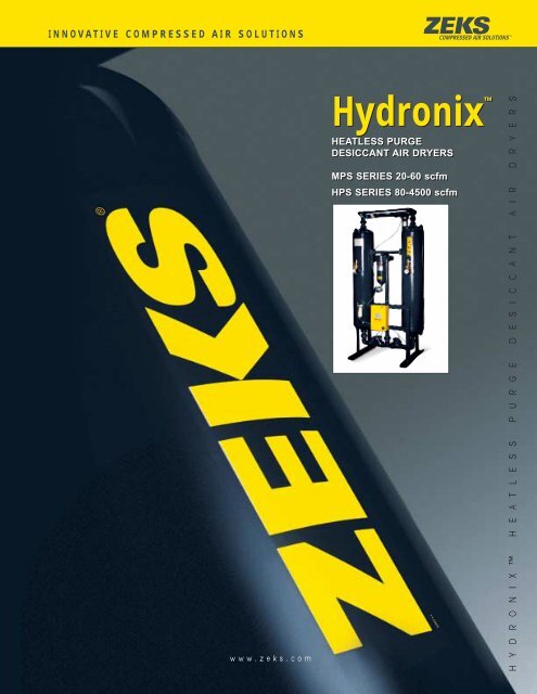
Hydronix <br />
HEATLESS PURGE<br />
HEATLESS PURGE<br />
DESICCANT AIR DRYERS<br />
MPS SERIES 20-60 scfm<br />
HPS SERIES 80-4500 scfm<br />
H Y D R O N I X H E A T L E S S P U R G E D E S I C C A N T A I R D R Y E R S
DELIVERING POWERFUL COMPRESSED AIR<br />
Use of <strong>ZEKS</strong>’ Hydronix Desiccant <strong>Air</strong><br />
Dryers is an efficient and reliable means of<br />
providing dry compressed air for extremely<br />
moisture-sensitive applications. These<br />
dryers use a heatless purge process for<br />
desiccant regeneration to deliver dry<br />
compressed air that has a dew point of<br />
-40°F. Hydronix models can be selected<br />
to achieve dew points as low as -80ºF or<br />
-100°F. The heatless purge process<br />
consumes little energy while reliable valve<br />
and switching components provide<br />
consistent performance for long dryer life.<br />
Available in a broad range of compressed<br />
air flow capacities, the Hydronix dryer<br />
family employs proven design, reliable<br />
components and integrated controls to<br />
provide compatibility and continuous<br />
trouble-free operation in compressed air<br />
systems.<br />
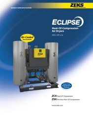
Purge pressure gauge<br />
indicates reactivation<br />
flow rate<br />
Removable stainless<br />
steel retainer screens<br />
High strength<br />
desiccant for<br />
long life<br />
Vessels in<br />
accordance with<br />
ASME Section VIII,<br />
Div. 1<br />
Visual dryer<br />
performance<br />
indicator<br />
Particulate<br />
control air<br />
line filter<br />
Enclosed wiring for<br />
maximum protection<br />
Purge flow adjustment valve<br />
Separate FILL and<br />
DRAIN ports<br />
Towers sized for low velocity<br />
and high contact time<br />
ASME required relief valves<br />
Tower pressure gauges<br />
Standard light indications:<br />
• Power ON<br />
• Left tower DRYING<br />
• Right tower DRYING<br />
Mufflers with built-in relief valves<br />
for low noise and maximum<br />
protection<br />
SIZING PROCEDURE<br />
For inlet flows at operating pressures<br />
other than 100 PSIG, multiply the<br />
standard capacity by the correction<br />
factor from the table below.<br />
Example:<br />
410 SCFM x .91 = 373 SCFM @ 90 PSIG<br />
For purge air requirements, multiply the<br />
inlet flow by the purge rate factor from<br />
the table.<br />
373 SCFM x .160 = 59.7 SCFM @ 90 PSIG<br />
Outlet Flow = Inlet Flow – Purge Flow<br />
OPERATING CONDITIONS<br />
Pressure PSIG Correction Factor Purge Rate<br />
75 .78 .190<br />
80 .82 .180<br />
85 .87 .170<br />
90 .91 .160<br />
95 .95 .155<br />
100 1.00 .150<br />
105 1.04 .140<br />
110 1.09 .135<br />
115 1.13 .130<br />
120 1.17 .125<br />
125 1.22 .120<br />
130 1.26 .117<br />
135 1.30 .113<br />
140 1.35 .109<br />
145 1.39 .106<br />
150 1.44 .102<br />
Solid state timer for<br />
accurate control and<br />
operation<br />
Simple, safe, reliable<br />
switching valves<br />
SELECTION CHART<br />
Model 20MPS 30MPS 40MPS 60MPS 80HPS 100HPS 140HPS<br />
Flow Capacity* -40° Dew Point 20 30 40 60 80 100 140<br />
-80° Dew Point 16 24 32 48 64 80 112<br />
-100° Dew Point 16 24 32 48 64 80 112<br />
Width in. (cm) 22 (56) 22 (56) 22 (56) 22 (56) 26 (66) 27 (69) 29 (74)<br />
Depth in. (cm) 15 (38) 15 (38) 15 (38) 15 (38) 26 (66) 26 (66) 26 (66)<br />
Height in. (cm) 31 (79) 44 (112) 44 (112) 56 (142) 85 (216) 85 (216) 85 (216)<br />
<strong>Air</strong> Connection In & Out 1/2"FPT 1/2"FPT 3/4"FPT 3/4"FPT 3/4"FPT 1"FPT 1"FPT<br />
Shipping Weight lbs. (kg) 200 (91) 230 (104) 255 (116) 300 (136) 480 (218) 500 (227) 650 (295)<br />
Desiccant Weight lbs. (kg) 22 (10) 44 (20) 44 (20) 65 (29) 89 (40) 89 (40) 164 (74)<br />
Maximum Working PSIG** 150 150 150 150 150 150 150<br />
*Capacities shown are for inlet flows at operating pressures of 100 PSIG<br />
**Consult factory for operating pressures in excess of 150 PSIG<br />
Note: Standard voltage for all models is 115/1/60 & 50<br />
Note: Operating dryers without a coalescing filter with auto drain will void warranty<br />
Note: Weights and dimensions are approximate<br />
Hydronix <br />
HEATLESS PURGE<br />
DESICCANT AIR DRYERS<br />
MPS SERIES 20-60 scfm<br />
HPS SERIES 80-4500 scfm<br />
Normally closed exhaust valves<br />
(spring-assisted) provide fail-safe<br />
operation<br />
(Shown with optional equipment)
DRYING CAPABILITY<br />
COMPRESSED AIR SOLUTIONS TM<br />
COMPRESSED AIR SOLUTIONS TM<br />
DRY AIR<br />
OUTLET<br />
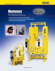
EFFICIENT OPERATION AND RELIABLE DESIGN<br />
The heatless dryer works by passing compressed air through a tower filled with<br />
desiccant. Moisture from the airstream is adsorbed onto the desiccant thereby<br />
producing extremely dry outlet air. While one tower is on-line performing the<br />
drying function, the second tower is off-line being regenerated by a portion<br />
(approx. 15%) of the discharge dry air flow.<br />
This operation is controlled by valves (V1 & V2) which divert the flow of air to the<br />
on-line tower and away from the regenerating tower. At the same time, a purge<br />
valve (V3 or V4) allows the regenerating air flow entering the off-line tower to<br />
escape and thereby purge the moisture adsorbed from the desiccant to the<br />
atmosphere. On a -40ºF dewpoint dryer, this process lasts for four minutes and<br />
thirty seconds, at which time repressurization of the off-line (regenerating) tower<br />
begins to prevent desiccant bed fluidization. The purge valve (V3 or V4) will close<br />
so that the off-line tower is allowed to repressurize.<br />
After repressurization is complete, the flow valves (V1 & V2) will divert the drying<br />
air flow to the previously off-line tower. Simultaneously, a purge valve (V3 or V4)<br />
will open allowing the previously on-line dryer tower to depressurize and begin<br />
regeneration. This will last for four minutes and thirty seconds at which point the<br />
process will again be reversed. The total cycle time is ten minutes.<br />
C<br />
C1<br />
O1<br />
PI1<br />
D<br />
PI3<br />
RV1 RV2<br />
PI2<br />
V1<br />
V3<br />
M1<br />
WET AIR<br />
INLET<br />
C2<br />
V5<br />
V2<br />
V4<br />
M2<br />
A<br />
DRYING FLOW<br />
REGENERATING FLOW<br />
B<br />
180HPS 280HPS 410HPS 560HPS 730HPS 920HPS 1140HPS 1630HPS 1910HPS 2300HPS 2800HPS 3300HPS 4500HPS<br />
180 280 410 560 730 920 1140 1630 1910 2300 2800 3300 4500<br />
144 224 328 448 584 736 912 1304 1528 1840 2240 2640 3600<br />
144 224 328 448 584 736 912 1304 1528 1840 2240 2640 3600<br />
35 (89) 37 (94) 47 (119) 49 (124) 61 (155) 63 (160) 65 (165) 88 (224) 92 (234) 94 (239) 94 (239) 113 (287) 119 (302)<br />
30 (76) 30 (76) 33 (84) 33 (84) 48 (122) 48 (122) 48 (122) 57 (145) 57 (145) 57 (145) 57 (145) 63 (160) 63 (160)<br />
87 (221) 90 (229) 92 (234) 95 (241) 96 (244) 100 (254) 101 (257) 115 (292) 110 (279) 110 (279) 123 (312) 121 (307) 125 (318)<br />
1-1/2"FPT 1-1/2"FPT 2"FPT 2"FPT 3"FPT 3"FPT 3"FPT 4"FLG 4"FLG 4"FLG 4"FLG 6"FLG 6"FLG<br />
700 (318) 830 (377) 1205 (547) 1400 (636) 1590 (722) 1825 (828) 2478 (1125) 3050 (1385) 3600 (1634) 5200 (2361) 6800 (3087) 7500 (3405) 9600 (4358)<br />
164 (74) 266 (121) 400 (181) 538 (244) 756 (343) 918 (416) 1166 (529) 1830 (830) 2497 (1133) 2300 (1043) 2766 (1255) 3500 (1588) 5800 (2631)<br />
150 150 150 150 150 150 150 150 150 150 150 150 150
FEATURES<br />
MPS HPS<br />
MODEL 20-60 80-1140 1630-4500<br />
Power Cord S - -<br />
Wall Mounting (std. units only) S - -<br />
Power ON Light S S S<br />
Tower Sequencing Light S S S<br />
Tower Pressure Gauges S S S<br />
Tower Relief Valves O S S<br />
ASME Stamped Vessels S S S<br />
CRN Stamped Vessels S S O<br />
Removable SS Retainer Screens S S S<br />
Fill and Drain Ports (Separate) S S S<br />
Solid State Timer Controls S S S<br />
Shipped with Desiccant S S S*<br />
Adjustable Purge O S S<br />
Weatherproof/NEMA 4 O O O<br />
NEMA 12** O O O<br />
NEMA 7 O O O<br />
Moisture Indicator O S S<br />
Control <strong>Air</strong> Line Filter - S S<br />
Control <strong>Air</strong> Line Filter Shutoff Valve - O S<br />
Pneumatic Operation O O O<br />
Failure to Shift Alarm O O O<br />
Moisture Load Control (includes FTS) O O O<br />
High Humidity Alarm O O O<br />
Remote Alarm Contacts O O O<br />
Factory Mounted Pre and Afterfilters O O O<br />
3-Valve Bypass for Filters and/or Dryer O O O<br />
250 PSIG Design O O O<br />
UL/ULC Certified Enclosure O O O<br />
S-Standard<br />
O-Optional<br />
Hydronix <br />
HEATLESS PURGE<br />
DESICCANT AIR DRYERS<br />
MPS SERIES 20-60 scfm<br />
HPS SERIES 80-4500 scfm<br />
1302 Goshen Parkway<br />
West Chester, PA 19380<br />
610-692-9100 800-888-2323<br />
FAX 610-692-9192<br />
www.zeks.com<br />
* Models 2800-4500 shipped separately<br />
**Built to NEMA 4 Standards<br />
DRYER COMPONENTS<br />
The Valves<br />
The control valves used on the HPS series of<br />
<strong>ZEKS</strong> Hydronix heatless desiccant dryers are<br />
non-lubricated, air-operated, diaphragm<br />
valves. The valve design allows for higher<br />
flows with a lower associated pressure<br />
drop than alternate valve designs. The<br />
valve’s unique seating design is more<br />
reliable than four way or shuttle valves,<br />
reducing the probability of valve failure<br />
due to desiccant dust and other foreign contaminants. Integral<br />
moving parts made of non-corrosive material, in conjunction with<br />
a preformed and stress relieved diaphragm, provide durability and<br />
long cycle life. In the demanding fast-cycling world of heatless<br />
desiccant dryers, any type of valve is subject to maintenance. In<br />
those instances, it is crucial that repair can be completed quickly<br />
to minimize downtime. The <strong>ZEKS</strong> Hydronix valves are designed<br />
so that if valve repair is required, all internal components can be<br />
easily removed and replaced without disturbing dryer piping or<br />
removing the valve body.<br />
The Timer<br />
The Hydronix desiccant dryer is<br />
controlled by a state-of-the-art timer,<br />
delivering consistent, trouble-free dryer<br />
operation. This device requires no<br />
adjustments in order to achieve reliable<br />
sequencing of the valve cycling. Also<br />
available within the solid state timer technology is the capability of<br />
reducing the amount of regeneration air consumed with the<br />
addition of the <strong>ZEKS</strong> <strong>Air</strong>Mizer feature.<br />
<strong>Air</strong>Mizer<br />
The <strong>ZEKS</strong> <strong>Air</strong>Mizer option features a solid<br />
state controller integrated with a<br />
moisture analyzer which allows for<br />
automatic adjustment of purge air<br />
usage based on actual demand. The<br />
<strong>Air</strong>Mizer prevents the purge exhaust<br />
valves from opening until a predetermined<br />
moisture load is adsorbed by the desiccant<br />
beds. This is achieved by the use of in-bed air sampling probes<br />
which continuously monitor the “drying tower” for moisture<br />
content. Unlike other systems that are based on indirect readings<br />
such as temperature rise, inlet loading conditions or desiccant<br />
conductivity, the <strong>Air</strong>Mizer monitors exactly what you paid for —<br />
dry air. As long as the sampling probes “see” dry air, no purge air<br />
is consumed. With the use of the <strong>Air</strong>Mizer, yearly operating costs<br />
can be substantially reduced. As an addition to the <strong>Air</strong>Mizer<br />
option, failure to shift alarm is included.<br />
Specifications, illustrative materials and descriptions contained herein were as accurate as known at the time<br />
this publication was approved for printing. The company reserves the right to change specifications,<br />
discontinue models, equipment or design without notice and without incurring obligation. The information<br />
set out in this brochure is for preliminary information only and is not intended to constitute any representation<br />
or warranty by <strong>ZEKS</strong> to potential customers or to form the basis of a contract with any customer.<br />
©2001, <strong>ZEKS</strong> <strong>Compressed</strong> <strong>Air</strong> <strong>Solutions</strong> Form: HPS-0201-7.5M-DBO Printed in USA