4-th 4-channel fm radio control system quick ... - Tower Hobbies
4-th 4-channel fm radio control system quick ... - Tower Hobbies
4-th 4-channel fm radio control system quick ... - Tower Hobbies

Create successful ePaper yourself
Turn your PDF publications into a flip-book with our unique Google optimized e-Paper software.
®<br />
®<br />
<br />
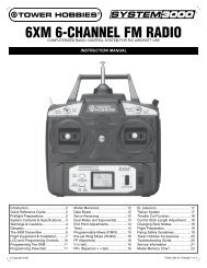
4-TH 4-CHANNEL FM RADIO CONTROL SYSTEM<br />
INSTRUCTION MANUAL FOR R/C AIRPLANE USE<br />
First of all, let me just say “Thank You!” for choosing <strong>th</strong>e <strong>Tower</strong> <strong>Hobbies</strong> ® System 3000 4-TH! All of us here at <strong>Tower</strong><br />
<strong>Hobbies</strong> are very pleased wi<strong>th</strong> <strong>th</strong>e 4-TH, because we feel it offers you, <strong>th</strong>e <strong>Tower</strong> <strong>Hobbies</strong> customer, one of <strong>th</strong>e very best values<br />
available in an airplane <strong>system</strong>.<br />
The 4-TH offers 4-<strong>channel</strong> <strong>control</strong>, enough for trainer and many sport models. As an FM narrow-band <strong>system</strong>, it's far less<br />
vulnerable to interference <strong>th</strong>an AM <strong>radio</strong>s. The narrow-band transmitter and dual-conversion receiver enhance strong <strong>control</strong><br />
by filtering and boosting <strong>th</strong>e signal. Combined, <strong>th</strong>ey'll provide you wi<strong>th</strong> smoo<strong>th</strong>, glitch-free operation even in today's “noisiest”<br />
<strong>radio</strong> environments.<br />
Those are big pluses, but we went even fur<strong>th</strong>er to make <strong>th</strong>e 4-TH <strong>th</strong>e most complete<br />
4-<strong>channel</strong> <strong>radio</strong> we've ever offered. The case has been ergonomically designed to ensure a<br />
more comfortable fit for your hands, allowing you many hours of flying enjoyment. You also<br />
receive such advantages as a full set of NiCd batteries wi<strong>th</strong> charger, reversing switches for<br />
all <strong>channel</strong>s, improved trainer jack and more.<br />
Packed wi<strong>th</strong> easy-to-use features and complete wi<strong>th</strong> a 1-year limited warranty, <strong>th</strong>e<br />
4-TH is a valuable investment toward superior model <strong>control</strong>. Congratulations on your<br />
purchase and happy flying!<br />
Sincerely,<br />
QUICK REFERENCE GUIDE<br />
Bruce R. Holecek<br />
Founder and Chief Executive Officer,<br />
<strong>Tower</strong> <strong>Hobbies</strong><br />
NOTE: This Quick Reference Guide is a condensed version of all<br />
information given in <strong>th</strong>is manual. We strongly recommend you<br />
first read <strong>th</strong>is entire manual before operating your 4-TH <strong>system</strong><br />
or your model.<br />
1. Charge <strong>th</strong>e transmitter and receiver batteries for 15 hours wi<strong>th</strong><br />
<strong>th</strong>e included charger.<br />
2. Connect servos, 4-cell battery pack and switch harness to <strong>th</strong>e<br />
receiver as shown at right.<br />
3. Turn on <strong>th</strong>e transmitter and <strong>th</strong>en turn on <strong>th</strong>e receiver<br />
switch harness.<br />
4. Center all four transmitter trim levers. Make sure all servos<br />
operate according to transmitter stick movements.<br />
5. Turn off <strong>th</strong>e <strong>system</strong>, receiver first, <strong>th</strong>en transmitter.<br />
6. Wrap <strong>th</strong>e receiver and receiver battery in foam rubber<br />
(HCAQ1000 or HCAQ1050) for protection from vibration and<br />
hard landings.<br />
7. Install <strong>th</strong>e entire <strong>radio</strong> <strong>system</strong> into your model as shown in <strong>th</strong>e<br />
model's instruction manual (see receiver picture to <strong>th</strong>e right<br />
for proper <strong>channel</strong> usage).<br />
8. If you need to reverse <strong>th</strong>e direction in which a servo rotates, locate<br />
<strong>th</strong>e reversing switch for <strong>th</strong>e desired <strong>channel</strong> on <strong>th</strong>e bottom front<br />
of <strong>th</strong>e transmitter and slide it to <strong>th</strong>e “REVERSE” position.<br />
9. Range test <strong>th</strong>e <strong>radio</strong> <strong>system</strong> prior to flight. Wi<strong>th</strong> <strong>th</strong>e transmitter<br />
antenna collapsed, you should be able to smoo<strong>th</strong>ly <strong>control</strong><br />
movement of all <strong>control</strong> surfaces on your model from at least<br />
100ft on <strong>th</strong>e ground.<br />
Antenna<br />
Charge<br />
Plug<br />
Trainer<br />
Switch<br />
Throttle,<br />
Rudder<br />
Stick<br />
Throttle Trim<br />
Rudder Trim<br />
Crystal Holder<br />
Battery<br />
Plug<br />
Receiver (Rx)<br />
Switch<br />
Harness<br />
Transmitter (Tx)<br />
Elevator Trim<br />
Elevator,<br />
Aileron<br />
Stick<br />
Aileron Trim<br />
Power Switch<br />
Reversing Switches<br />
Rudder<br />
CH 4<br />
Throttle<br />
CH 3<br />
Elevator<br />
CH 2<br />
Aileron<br />
CH 1
PREFLIGHT PRECAUTIONS<br />
PAGE 2<br />
Please read <strong>th</strong>is entire manual carefully and use your <strong>radio</strong> <strong>system</strong> safely.<br />
Pay special attention to all precautions and warnings to ensure <strong>th</strong>e safest operation.<br />
WARNINGS<br />
• Do not fly simultaneously on a frequency <strong>th</strong>at is already<br />
being used in your area. Doing so could cause unwanted<br />
interference, a crash and possibly bodily harm.<br />
• Always attach <strong>th</strong>e proper frequency flag to <strong>th</strong>e<br />
transmitter’s (Tx's) antenna when flying. This alerts o<strong>th</strong>ers<br />
at <strong>th</strong>e flying field as to which frequency you are using.<br />
• Do not fly in <strong>th</strong>e rain or at night. Water can permanently<br />
damage many of <strong>th</strong>e components in <strong>th</strong>e <strong>radio</strong> <strong>system</strong>,<br />
possibly causing loss of <strong>control</strong> and a crash.<br />
• Only fly at designated R/C flying fields. Fly at safe<br />
distances away from o<strong>th</strong>er people, objects in <strong>th</strong>e air,<br />
buildings, electrical lines, or any o<strong>th</strong>er object which<br />
could possibly impede safe flying. Failure to do so could<br />
cause a crash and possibly bodily harm and physical<br />
damage to o<strong>th</strong>er property.<br />
• Extend <strong>th</strong>e Tx and recevier (Rx) antennas to maximum<br />
leng<strong>th</strong> when flying. Make sure <strong>th</strong>e Tx antenna is <strong>th</strong>readed<br />
into <strong>th</strong>e Tx tightly. Always test <strong>th</strong>e <strong>radio</strong> <strong>system</strong> before<br />
use. Make sure <strong>th</strong>e operation of each <strong>channel</strong> in <strong>th</strong>e <strong>radio</strong><br />
is in <strong>th</strong>e proper direction. If a <strong>channel</strong> does not accurately<br />
respond according to Tx stick input, do NOT fly <strong>th</strong>e<br />
plane. Check for and correct improperly functioning<br />
equipment before use. Failure to ensure proper <strong>radio</strong><br />
operation before flight could result in a crash.<br />
• During flight preparations, be certain to place <strong>th</strong>e Tx on<br />
its back when on <strong>th</strong>e ground, to prevent it from<br />
accidentally falling over and inadvertently moving <strong>th</strong>e<br />
<strong>th</strong>rottle stick to high speed.<br />
• Do not allow fuel or oil on <strong>th</strong>e plastic parts. Some plastics<br />
may melt when exposed to such materials.<br />
• BEFORE turning <strong>th</strong>e Tx's power switch “ON”, adjust <strong>th</strong>e<br />
<strong>th</strong>rottle stick to minimum speed position. After stopping <strong>th</strong>e<br />
engine turn “OFF” <strong>th</strong>e Rx's power switch, <strong>th</strong>en turn “OFF”<br />
<strong>th</strong>e Tx power switch. Failure to follow <strong>th</strong>is order could<br />
cause <strong>th</strong>e engine to go to full <strong>th</strong>rottle and cause an injury.<br />
• Do not make adjustments to <strong>th</strong>e <strong>radio</strong> <strong>system</strong> while <strong>th</strong>e<br />
engine is running unless absolutely necessary. Failure to<br />
do so could cause <strong>th</strong>e engine to accidentally go to high<br />
speed and cause an injury.<br />
• Always fully charge <strong>th</strong>e Tx and Rx NiCd batteries before<br />
each flight. Failure to do so could cause an inadvertent<br />
power failure and a crash. Use <strong>th</strong>e charger supplied wi<strong>th</strong><br />
<strong>th</strong>is <strong>system</strong>. If using ano<strong>th</strong>er charger, do not overcharge<br />
<strong>th</strong>e battery, as it could cause burns, fire, injury or o<strong>th</strong>er<br />
equipment damage. Do not short circuit <strong>th</strong>e NiCd battery<br />
terminals, as arcing, overheating or fire could result.<br />
• Do not leave <strong>th</strong>e <strong>radio</strong> <strong>system</strong>, batteries, model airplane or<br />
o<strong>th</strong>er modeling equipment wi<strong>th</strong>in <strong>th</strong>e reach of children.<br />
• Do not overheat or <strong>th</strong>row <strong>th</strong>e NiCd batteries into a fire.<br />
Leaking electrolyte from <strong>th</strong>e battery could cause injury,<br />
such as burns or blindness. IN CASE OF EMERGENCY,<br />
IMMEDIATELY FLUSH YOUR EYES, SKIN OR CLOTHES<br />
WITH PLENTY OF WATER AND SEE A DOCTOR.<br />
Recycle <strong>th</strong>e battery when no longer in usable condition.<br />
• Store <strong>th</strong>e <strong>radio</strong> wi<strong>th</strong> all NiCd batteries in <strong>th</strong>e discharged state<br />
and be certain to fully charge <strong>th</strong>e batteries just prior to use.<br />
• Do not store <strong>th</strong>e <strong>radio</strong> <strong>system</strong> in extreme heat (exceeding<br />
104°F) or cold (below -14°F), in direct sunlight, in high<br />
humidity, in high vibration environments or in dusty areas.<br />
BEFORE INSTALLA<br />
ALLATION<br />
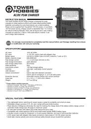
The rechargeable batteries inside of <strong>th</strong>e Tx and <strong>th</strong>e Rx pack must be fully charged prior to use. Plug <strong>th</strong>e supplied charger into<br />
a 110V AC wall outlet. Connect <strong>th</strong>e charger's output leads to <strong>th</strong>e Rx pack and <strong>th</strong>e charge jack located on <strong>th</strong>e side of <strong>th</strong>e Tx<br />
(make sure <strong>th</strong>e power switch is OFF). The corresponding LEDs will illuminate on <strong>th</strong>e charger when a good electrical<br />
connection is made wi<strong>th</strong> each battery. When charging is complete, disconnect <strong>th</strong>e charge leads from <strong>th</strong>e batteries and<br />
disconnect <strong>th</strong>e charger from <strong>th</strong>e wall.
THE TRANSMITTER PAGE 3<br />
Trainer Jack<br />
Antenna<br />
Battery Cover<br />
Trainer Switch<br />
Elevator Trim<br />
Throttle Trim<br />
Aileron<br />
CH1<br />
Throttle<br />
CH3<br />
Rudder<br />
CH4<br />
RIGHT<br />
GIMBAL<br />
Elevator<br />
CH2<br />
Aileron Trim<br />
LEFT<br />
GIMBAL<br />
Power Switch<br />
Charge Jack<br />
Rudder Trim<br />
Power LEDs<br />
Over 9V: Bo<strong>th</strong> on<br />
8.5V – 9.0V: Red on, green off<br />
Under 8.5V: Red flashes, green off<br />
The 4-TH transmitter (Tx) is designed for mode-II operation.<br />
Mode-II is commonly used <strong>th</strong>roughout <strong>th</strong>e U.S., where <strong>th</strong>e<br />
aileron and <strong>th</strong>e elevator are <strong>control</strong>led wi<strong>th</strong> <strong>th</strong>e right stick and <strong>th</strong>e<br />
<strong>th</strong>rottle and rudder are <strong>control</strong>led wi<strong>th</strong> <strong>th</strong>e left stick. Operation of<br />
<strong>control</strong>s and <strong>th</strong>eir assigned <strong>channel</strong> numbers are as follows:<br />
Aileron Control (CH1): When <strong>th</strong>e aileron stick is moved to<br />
<strong>th</strong>e right, <strong>th</strong>e right aileron is raised and <strong>th</strong>e left aileron is<br />
lowered and <strong>th</strong>e plane banks to <strong>th</strong>e right. When <strong>th</strong>e aileron<br />
stick is moved to <strong>th</strong>e left, <strong>th</strong>e ailerons move in <strong>th</strong>e opposite<br />
direction and <strong>th</strong>e airplane banks left. To level <strong>th</strong>e plane, <strong>th</strong>e<br />
aileron stick must be moved in <strong>th</strong>e opposite direction and<br />
back to center.<br />
Elevator Control (CH2): When <strong>th</strong>e elevator stick is pulled<br />
back, <strong>th</strong>e tail elevator is raised and <strong>th</strong>e tail of <strong>th</strong>e plane is<br />
forced down, <strong>th</strong>us causing <strong>th</strong>e plane to climb (UP operation).<br />
When <strong>th</strong>e elevator stick is pushed forward, <strong>th</strong>e elevator is<br />
lowered; <strong>th</strong>e tail of <strong>th</strong>e plane is forced up, <strong>th</strong>us causing <strong>th</strong>e<br />
plane to descend (DOWN operation).<br />
Figure 1<br />
Servo Reversing<br />
Switches<br />
Throttle Control (CH3): When <strong>th</strong>e <strong>th</strong>rottle stick is pulled<br />
back, <strong>th</strong>e engine <strong>th</strong>rottle lever arm moves to <strong>th</strong>e SLOW (low<br />
speed) side. When <strong>th</strong>e <strong>th</strong>rottle stick is pushed forward, <strong>th</strong>e<br />
<strong>th</strong>rottle lever arm moves to <strong>th</strong>e HIGH (high speed) side.<br />
Rudder Control (CH4): When <strong>th</strong>e rudder stick is moved to <strong>th</strong>e<br />
right, <strong>th</strong>e rudder moves to <strong>th</strong>e right and <strong>th</strong>e nose points to <strong>th</strong>e<br />
right, <strong>th</strong>us causing <strong>th</strong>e plane to turn right. When <strong>th</strong>e rudder<br />
stick is moved to <strong>th</strong>e left, <strong>th</strong>e rudder moves to <strong>th</strong>e left and <strong>th</strong>e<br />
nose points to <strong>th</strong>e left, <strong>th</strong>us causing <strong>th</strong>e plane to turn left.<br />
During normal conditions, <strong>th</strong>e range, or safe operating<br />
distance from <strong>th</strong>e Tx to <strong>th</strong>e Rx is “line of sight”. This means<br />
<strong>th</strong>e 4-TH should maintain complete <strong>control</strong> any time you can<br />
see your model. The 4-TH operates on <strong>th</strong>e 72MHz frequency<br />
band. There are 50 different <strong>channel</strong>s available for <strong>th</strong>is <strong>system</strong><br />
ranging from 72.010MHz (Ch11) <strong>th</strong>rough 72.990MHz<br />
(Ch60). For safety reasons, you must always be aware of what<br />
<strong>channel</strong> you are using so <strong>th</strong>at no two <strong>radio</strong>s in <strong>th</strong>e same area<br />
are EVER operating on <strong>th</strong>e same frequency simultaneously.
THE TRANSMITTER (CONTINUED)<br />
PAGE 4<br />
The rechargeable batteries inside <strong>th</strong>e transmitter and <strong>th</strong>e receiver<br />
pack must be fully charged prior to use. Plug <strong>th</strong>e charger into a<br />
110V AC wall outlet. Next, connect <strong>th</strong>e charger's output leads to<br />
<strong>th</strong>e Rx battery pack or switch harness and Tx charge jack. The<br />
respective charger LEDs will illuminate as you connect <strong>th</strong>e<br />
charger to <strong>th</strong>e batteries. Charge each battery for 15 hours. The<br />
batteries may become warm as <strong>th</strong>ey charge. This is normal and a<br />
good indication <strong>th</strong>at <strong>th</strong>e batteries are becoming fully charged.<br />
NOTE: The Tx and Rx batteries should be charged <strong>th</strong>e night<br />
before each use. If <strong>th</strong>e batteries have not been used for several<br />
mon<strong>th</strong>s, you may need to cycle <strong>th</strong>em prior to use. Cycling is<br />
<strong>th</strong>e process of fully charging, <strong>th</strong>en discharging, rechargeable<br />
batteries to help maximize <strong>th</strong>eir charge capacity and run<br />
time. To cycle a battery, charge it for 15 hours and <strong>th</strong>en<br />
discharge it by turning on <strong>th</strong>e transmitter. The Tx's voltage<br />
indicator should not drop into <strong>th</strong>e red zone (wi<strong>th</strong> <strong>th</strong>e antenna<br />
extended) for 90 to 120 minutes. If it does, cycle <strong>th</strong>e batteries<br />
again. If <strong>th</strong>e batteries still cause <strong>th</strong>e voltage indicator to drop<br />
in less <strong>th</strong>an 90 minutes after repeated cycles, battery<br />
replacement is recommended. The old batteries should be<br />
disposed of at a recycling center.<br />
STICK LEVER LENGTH ADJUSTMENTS<br />
The stick leng<strong>th</strong>s can be adjusted to match different<br />
preferences (see figure 2). Turn <strong>th</strong>e stick head (A) counterclockwise<br />
and stick head (B) clockwise to unlock. Adjust <strong>th</strong>e<br />
leng<strong>th</strong> to your preference and lock in reverse order.<br />
To Loosen:<br />
Stick<br />
Head A<br />
Stick<br />
Head B<br />
Figure 2<br />
TRAINER FUNCTIONS<br />
The trainer function is a very effective way to teach o<strong>th</strong>ers<br />
how to fly. To use it, <strong>th</strong>e special trainer cord (sold separately)<br />
is necessary. The trainer cord comes in 2 configurations,<br />
based on what transmitter is being used as a “Buddy Box”.<br />
Configuration 1 can be connected to <strong>Tower</strong> 6FM, 4FM<br />
and Futaba ® SKYSPORT4, FF5, SKYSPORT6, 7U series, 8U<br />
series and PCM1024Z series transmitters. The <strong>Tower</strong> trainer<br />
cord TOWM6081 or <strong>th</strong>e Futaba FUTM4420 may be used in<br />
<strong>th</strong>is configuration.<br />
Configuration 2 can be connected to ano<strong>th</strong>er <strong>Tower</strong> 4-TH<br />
and <strong>th</strong>e new Futaba 9C series transmitters. The <strong>Tower</strong> trainer<br />
cord TOWM6082 or <strong>th</strong>e Futaba FUTM4415 may be used in<br />
<strong>th</strong>is configuration.<br />
OPERATING INSTRUCTIONS<br />
Connect <strong>th</strong>e student and instructor transmitters wi<strong>th</strong> <strong>th</strong>e<br />
trainer cord.<br />
Instructor side:<br />
Turn on <strong>th</strong>e power switch and extend <strong>th</strong>e antenna to its full<br />
leng<strong>th</strong>. When <strong>th</strong>e trainer switch is not pressed, <strong>th</strong>e instructor<br />
has <strong>control</strong>. When <strong>th</strong>e spring-loaded trainer switch is pressed<br />
and held, <strong>control</strong> of <strong>th</strong>e airplane is transferred to <strong>th</strong>e student.<br />
Student side:<br />
WARNING: Never turn on <strong>th</strong>e student transmitter power<br />
switch. Turning on <strong>th</strong>e power switch will cause interference<br />
and a crash. Set <strong>th</strong>e student and instructor transmitter <strong>control</strong>s<br />
to <strong>th</strong>e same settings. For example, if <strong>th</strong>e direction of operation<br />
of any <strong>channel</strong> is reversed, <strong>control</strong> will be incorrect and <strong>th</strong>e<br />
plane will crash. All trim settings on <strong>th</strong>e student Tx should<br />
match <strong>th</strong>at of <strong>th</strong>e instructor Tx. The instructor’s Tx can only be<br />
an FM (PPM) type transmitter. If <strong>th</strong>e modulation me<strong>th</strong>od is<br />
different, <strong>control</strong> is impossible.<br />
Before training, it is important to follow <strong>th</strong>ese preflight checks:<br />
1. Connect <strong>th</strong>e appropriate trainer cord to <strong>th</strong>e appropriate trainer<br />
cord jack; <strong>th</strong>ey are located on <strong>th</strong>e rear of <strong>th</strong>e transmitters.<br />
2. Turn off <strong>th</strong>e instructor’s Tx and Rx switch harness in <strong>th</strong>e<br />
model. Caution: Do not turn on <strong>th</strong>e student's Tx or<br />
damage to <strong>th</strong>e instructor's Tx will occur. The student's Tx<br />
will receive its power from <strong>th</strong>e instructor's Tx.<br />
3. Set <strong>th</strong>e trims and reversing switches on <strong>th</strong>e student's Tx to<br />
match <strong>th</strong>e instructor's Tx.<br />
4. Press and hold <strong>th</strong>e trainer switch on <strong>th</strong>e instructor's Tx. The<br />
student should now be able to <strong>control</strong> <strong>th</strong>e aircraft. Caution:<br />
Make sure <strong>th</strong>e student's Tx is properly <strong>control</strong>ling <strong>th</strong>e<br />
aircraft. Any difference in operation could cause loss of<br />
<strong>control</strong> during flight.<br />
5. Release <strong>th</strong>e trainer switch in order to confirm <strong>th</strong>at <strong>th</strong>e<br />
instructor's Tx has regained <strong>control</strong> of <strong>th</strong>e model.<br />
6. You are now ready to begin flight training.<br />
Caution: Training should only begin if an experienced pilot is<br />
<strong>control</strong>ling <strong>th</strong>e instructor's transmitter. Failure to do so could<br />
put yourself and o<strong>th</strong>ers in <strong>th</strong>e area at risk of injury or property<br />
damage. To make your R/C modeling experience more<br />
enjoyable, it is recommended <strong>th</strong>at you get an experienced<br />
instructor for your first flights. Experienced instructors can be<br />
located at your local R/C club; some even offer training<br />
programs and insured newcomer training. To locate a club in<br />
your area, you can contact <strong>th</strong>e national Academy of Model<br />
Aeronautics (AMA), which has more <strong>th</strong>an 2,500 chartered<br />
clubs across <strong>th</strong>e country. Please contact <strong>th</strong>e AMA at:<br />
Academy of Model Aeronautics<br />
5151 East Memorial Drive<br />
Muncie, IN 47302-9252<br />
Tel: (800) 435-9262 Fax: (765)741-0057<br />
http://www.modelaircraft.org/
FREQUENCY FLAG PAGE 5<br />
Use <strong>th</strong>e frequency flags <strong>th</strong>at are supplied wi<strong>th</strong> your R/C<br />
<strong>system</strong> so <strong>th</strong>at o<strong>th</strong>er modelers at <strong>th</strong>e flying field can identify<br />
your <strong>channel</strong> number. Attach <strong>th</strong>e flags to <strong>th</strong>e base of <strong>th</strong>e Tx<br />
antenna as shown in figure 3.<br />
Figure 3<br />
Side A<br />
Frequency board<br />
Band Number Seal (after sticking)<br />
Side B<br />
SERVO O INSTALLA<br />
ALLATION<br />
All servos should be mounted as shown in <strong>th</strong>e model's<br />
instructions. Use <strong>th</strong>e rubber grommets, screws and brass<br />
eyelets supplied when mounting your servos (see figure 4).<br />
Do NOT over-tighten <strong>th</strong>e mounting screws. The servos should<br />
be able to move slightly to compensate for engine vibration.<br />
For each servo, use a servo horn long enough to accommodate<br />
<strong>th</strong>e entire range of movement for <strong>th</strong>at particular <strong>control</strong>.<br />
When mounting <strong>th</strong>e servos, make sure <strong>th</strong>e pushrods are not<br />
too loose or bind in anyway. Pushrods should be capable of<br />
operating <strong>th</strong>e full range of <strong>th</strong>e servo. This can be tested by<br />
moving <strong>th</strong>e Tx sticks to maximum positions several times<br />
while observing <strong>th</strong>e movement of <strong>th</strong>e <strong>control</strong> services. If a<br />
servo is binding or sticks in flight, a greater current drain on<br />
<strong>th</strong>e battery is applied, <strong>th</strong>us shortening <strong>th</strong>e flight time of <strong>th</strong>e<br />
Figure 4<br />
model. Binding can also cause damage to <strong>th</strong>e servo and loose<br />
linkages could result in poor <strong>control</strong> of <strong>th</strong>e aircraft.<br />
Because <strong>th</strong>ere are a variety of specific applications for servos<br />
in R/C modeling, different servos are designed for different<br />
applications. <strong>Tower</strong> <strong>Hobbies</strong> offers a large line-up of servos<br />
which you can choose from.<br />
RECEIVER, SWITCH HARNESS & RECEIVER BATTERB<br />
TTERY Y INSTALLA<br />
ALLATION<br />
After <strong>th</strong>e receiver and servos are mounted in your model,<br />
connect <strong>th</strong>e Rx to <strong>th</strong>e servos and switch harness per <strong>th</strong>e<br />
diagram in figure 5. Always insert <strong>th</strong>e servo and battery or<br />
switch harness connector into <strong>th</strong>e Rx firmly, to ensure<br />
solid physical and electrical connections are made.<br />
Turn on <strong>th</strong>e Tx, <strong>th</strong>en <strong>th</strong>e Rx switch harness. Make sure all<br />
servos operate according to <strong>th</strong>e movement of <strong>th</strong>e Tx<br />
sticks. Center all trim levers, turn off <strong>th</strong>e Rx switch<br />
harness, <strong>th</strong>en <strong>th</strong>e transmitter and be careful not to move<br />
<strong>th</strong>e servo arms from <strong>th</strong>eir centered position during<br />
installation. The servo connectors are keyed to prevent<br />
improper connection, but do pay close attention when<br />
connecting <strong>th</strong>em to <strong>th</strong>e receiver. The black wire goes<br />
toward <strong>th</strong>e outside edge of <strong>th</strong>e receiver case. Mount <strong>th</strong>e<br />
switch harness to <strong>th</strong>e side of <strong>th</strong>e fuselage away from <strong>th</strong>e<br />
engine exhaust (refer to your model's instruction manual).<br />
Connect <strong>th</strong>e red plug to <strong>th</strong>e receptacle on <strong>th</strong>e Rx marked<br />
“B” for battery. Connect <strong>th</strong>e 4.8V Rx battery to <strong>th</strong>e female<br />
plug on <strong>th</strong>e switch harness. Wrap <strong>th</strong>e receiver and battery<br />
in 1/4"-1/2" foam rubber (HCAQ1000, HCAQ1050) to<br />
reduce vibration. Route <strong>th</strong>e receiver antenna according to<br />
<strong>th</strong>e model's instructions. Do NOT cut or coil <strong>th</strong>e antenna<br />
or you may lose adequate operational range.<br />
Antenna<br />
Charge<br />
Plug<br />
Battery<br />
Plug<br />
Receiver (Rx)<br />
Switch<br />
Harness<br />
Figure 5<br />
Rudder<br />
CH 4<br />
Throttle<br />
CH 3<br />
Elevator<br />
CH 2<br />
Aileron<br />
CH 1<br />
NOTE: You may mount <strong>th</strong>e battery fore or aft of <strong>th</strong>e location<br />
shown to better balance <strong>th</strong>e aircraft. Range test <strong>th</strong>e <strong>radio</strong> <strong>system</strong><br />
prior to flight. Wi<strong>th</strong> <strong>th</strong>e Tx antenna collapsed, you should be<br />
able to smoo<strong>th</strong>ly <strong>control</strong> movement of all <strong>control</strong> surfaces on<br />
your model from at least 100 ft. on <strong>th</strong>e ground. If not, refer to<br />
<strong>th</strong>e 4-TH's Troubleshooting Guide on page 7 before proceeding.
FCC C STATEMENTS<br />
TEMENT PAGE 6<br />
This device complies wi<strong>th</strong> part 15 of <strong>th</strong>e FCC rules. Operation is subject to <strong>th</strong>e following two conditions.<br />
(1) This device may not cause harmful interference.<br />
(2) This device must accept any interference received, including interference <strong>th</strong>at may cause undesired operation.<br />
The user is cautioned <strong>th</strong>at changes or modifications not expressly approved by <strong>th</strong>e party responsible for compliance could<br />
void <strong>th</strong>e user’s au<strong>th</strong>ority to operate <strong>th</strong>e equipment.<br />
RECYCLING CLING OF NICD BATTERIESB<br />
The <strong>Tower</strong> <strong>Hobbies</strong> 4-TH Radio <strong>system</strong> contains nickel-cadmium (NiCd) batteries in <strong>th</strong>e Tx as<br />
well as a separate pack to power <strong>th</strong>e receiver. The RBRC ® Battery Cycling Seal on <strong>th</strong>e NiCd<br />
batteries indicate <strong>th</strong>at <strong>Tower</strong> <strong>Hobbies</strong> is voluntarily participating in an industry program to<br />
collect and recycle <strong>th</strong>ese batteries at <strong>th</strong>e end of <strong>th</strong>eir useful life, when taken out of service in <strong>th</strong>e<br />
United States and Canada. The RBRC program provides a convenient alternative to placing used<br />
NiCd batteries into <strong>th</strong>e trash or <strong>th</strong>e municipal waste <strong>system</strong>, which may be illegal in your area.<br />
Please call 1-800-8-BATTERY for information on NiCd battery recycling and disposal<br />
bans/restrictions in your area.<br />
4-TH SPECIFICATIONS<br />
Transmitter<br />
Channels: 4-<strong>channel</strong><br />
Transmitting frequencies: 72MHz band<br />
Modulation type: FM Narrow-band<br />
Nominal current drain: approx. 180mA<br />
Input power: 9.6V NiCd battery<br />
Output power:
SAFETY GUIDE (CONTINUED)<br />
PAGE 7<br />
available from AMA HQ). In any case, models using rocket motors as a<br />
primary means of propulsion are limited to a maximum weight of 3.3<br />
pounds and a G series motor. NOTE: A model aircraft is defined as an<br />
aircraft wi<strong>th</strong> or wi<strong>th</strong>out engine, not able to carry a human being.<br />
10. I will not operate any turbo jet engine (axial or centrifugal flow)<br />
unless I have obtained a special waiver for such specific operations from<br />
<strong>th</strong>e AMA President and Executive Director and I will abide by any<br />
restriction(s) imposed for such operation by <strong>th</strong>em. (NOTE: This does not<br />
apply to ducted fan models using piston engines or electric motors.)<br />
11. I will not consume alcoholic beverages prior to, nor during,<br />
participation in any model operations.<br />
RADIO CONTROL<br />
1. I will have completed a successful <strong>radio</strong> equipment ground range<br />
check before <strong>th</strong>e first flight of a new or repaired model.<br />
2. I will not fly my model aircraft in <strong>th</strong>e presence of spectators until I<br />
become a qualified flier, unless assisted by an experienced helper.<br />
3. I will perform my initial turn after takeoff away from <strong>th</strong>e pit or<br />
spectator areas and I will not <strong>th</strong>ereafter fly over pit or spectator areas,<br />
unless beyond my <strong>control</strong>.<br />
4. I will operate my model using <strong>radio</strong> <strong>control</strong> frequencies currently<br />
allowed by <strong>th</strong>e Federal Communications Commission. (Only properly<br />
licensed Amateurs are au<strong>th</strong>orized to operate equipment on Amateur<br />
Band Frequencies.)<br />
5. I will not knowingly operate an R/C <strong>system</strong> wi<strong>th</strong>in 3 miles of a pre-existing<br />
model club flying site wi<strong>th</strong>out a frequency sharing agreement wi<strong>th</strong> <strong>th</strong>at club.<br />
6. I will not fly my model aircraft in any racing competition which allows<br />
models over 20 pounds unless <strong>th</strong>at competition event is AMA<br />
sanctioned. (For <strong>th</strong>e purposes of <strong>th</strong>is paragraph, competition is defined<br />
as any situation where a winner is determined.)<br />
TROUBLESHOOTING TING GUIDE<br />
Problem Possible causes Solution<br />
Short range<br />
Short run-time<br />
Tx meter low<br />
Tx meter beyond<br />
red zone but servos<br />
do not function<br />
Collapsed Tx antenna.....................................Fully extend <strong>th</strong>e Tx antenna<br />
Interference ....................................................Check frequencies in area, check Rx<br />
installation<br />
Rx antenna poorly routed...............................Re-route Rx antenna<br />
Low Tx or Rx battery ......................................Charge batteries for 15 hours prior to use<br />
Rx or Tx out of tune .......................................Send <strong>radio</strong> to Hobby Services for tuning<br />
Severed Rx antenna........................................Send <strong>radio</strong> to Hobby Services for repair<br />
Crash damage ...............................................Send <strong>radio</strong> to Hobby Services for repair<br />
Low Tx or Rx batteries....................................Charge batteries for 15 hours prior to use<br />
Batteries need to be cycled ...........................See before Installation on page 3<br />
Binding servos causing excess battery drain......Free binding components in pushrods or<br />
moving surfaces. See model's manual.<br />
Too many servos for <strong>th</strong>e Rx pack used ...........Additional servos cause <strong>quick</strong>er battery<br />
drain. Use a Rx battery pack wi<strong>th</strong> a<br />
higher mAh rating.<br />
Tx batteries need charged .............................Charge Tx batteries for 15 hours<br />
Rx batteries need charged .............................Charge Rx batteries for 15 hours<br />
Rx switch in off position ................................Turn on switch harness<br />
Switch harness connected incorrectly ...........See <strong>quick</strong> reference guide on page 4<br />
Interference or servos glitching<br />
One glitching servo<br />
Ano<strong>th</strong>er Tx is on your <strong>channel</strong> ......................Do not operate your <strong>system</strong> until o<strong>th</strong>er<br />
<strong>system</strong> is not in use<br />
Outside interference ......................................Check your local R/C club for confirmation<br />
(Pagers, transmission towers) of dangerous<br />
frequencies in your area<br />
Engine or motor noise ....................................Reroute <strong>th</strong>e antenna or servo leads as far<br />
away from <strong>th</strong>e engine as possible. When<br />
using an electric motor, make sure <strong>th</strong>at<br />
<strong>th</strong>e proper capacitors (see motor<br />
installation instruction for details) have<br />
been mounted and <strong>th</strong>at <strong>th</strong>ere is a good<br />
electrical connection<br />
Bad servo ......................................................Send servo to Hobby Services for repair
WARRANTY<br />
1-YEAR LIMITED WARRANTY<br />
(U.S.A. and Canada Only)<br />
<strong>Tower</strong> <strong>Hobbies</strong> warrants <strong>th</strong>is product to be free from defects in materials and workmanship for a period of one (1) year from<br />
<strong>th</strong>e date of purchase. During <strong>th</strong>at period, <strong>Tower</strong> <strong>Hobbies</strong> will, at its option, repair or replace wi<strong>th</strong>out service charge any<br />
product deemed defective due to <strong>th</strong>ose causes. You will be required to provide proof of purchase (invoice or receipt). This<br />
warranty does not cover damage caused by abuse, misuse, alteration or accident. If <strong>th</strong>ere is damage stemming from <strong>th</strong>ese<br />
causes wi<strong>th</strong>in <strong>th</strong>e stated warranty period, <strong>Tower</strong> <strong>Hobbies</strong> will, at its option, repair or replace it for a service charge not greater<br />
<strong>th</strong>an 50% of its <strong>th</strong>en currant retail list price. Be sure to include your daytime telephone number in case we need to contact<br />
you about your repair. This warranty gives you specific rights. You may have o<strong>th</strong>er rights, which vary from state to state.<br />
For service on your <strong>Tower</strong> <strong>Hobbies</strong> product, warranty or non-warranty, send it post paid and insured to:<br />
HOBBY SERVICES<br />
1610 Interstate Drive<br />
Champaign, IL 61821<br />
Phone: (217) 398-0007<br />
CONTACTING TOWER HOBBIES<br />
Via phone:<br />
Toll-Free in <strong>th</strong>e US and Canada: 800-637-6050<br />
Outside <strong>th</strong>e US and Canada: 217-398-3636<br />
Toll-Free FAX in <strong>th</strong>e US and Canada: 800-637-7303<br />
FAX Outside <strong>th</strong>e US and Canada: 217-356-6608<br />
Via <strong>th</strong>e Internet:<br />
World Wide Web: http://www.towerhobbies.com<br />
Via mail:<br />
<strong>Tower</strong> <strong>Hobbies</strong><br />
P.O. Box 9078<br />
Champaign, IL 61826-9078<br />
Version 1.0<br />
TOWZ1262 for TOWJ41**<br />
• Entire contents © Copyright 2002 • The contents of <strong>th</strong>is manual are subject to change wi<strong>th</strong>out prior notice • <strong>Tower</strong> <strong>Hobbies</strong> is not responsible for <strong>th</strong>e use of <strong>th</strong>is product