422/4-PCI-335 - Commtech-fastcom.com
422/4-PCI-335 - Commtech-fastcom.com
422/4-PCI-335 - Commtech-fastcom.com

Create successful ePaper yourself
Turn your PDF publications into a flip-book with our unique Google optimized e-Paper software.
9011 E. 37TH STREET N<br />
WICHITA, KANSAS 67226-2006<br />
(316) 636-1131<br />
FAX (316) 636-1163<br />
http://www.<strong>com</strong>mtech-<strong>fast<strong>com</strong></strong>.<strong>com</strong>/<br />
COPYRIGHT (C) 2009, 2010, 2011<br />
All rights reserved, including those to reproduce this document or parts thereof in<br />
any form without permission in writing from <strong>Commtech</strong>, Inc.<br />
FASTCOM and the “Alpha Lemur” are registered trademarks of <strong>Commtech</strong>, Inc.<br />
IBM is a registered trademark of International Business Machines Corporation.<br />
Microsoft is a registered trademark of Microsoft Corporation.<br />
WINDOWS is a trademark of Microsoft Corporation.
REVISION NOTES<br />
REVISION PAGE NUMBER CHANGES MADE<br />
1.0 Document created<br />
1.1 10 CTS+/- pin numbers swapped<br />
Fix page numbers in TOC<br />
1.2 9 Added to the serial settings description<br />
1.3 16 Changed warranty to limited lifetime<br />
1.4 1 Updated “CE” certificate<br />
1.5 16 Updated Limitation of Liability<br />
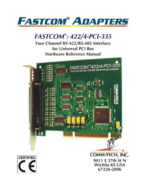
Fast<strong>com</strong> ® : <strong>422</strong>/4-<strong>PCI</strong>-<strong>335</strong>
TABLE OF CONTENTS<br />
EUROPEAN UNION DECLARATION OF CONFORMITY ........................................................ 1<br />
INTRODUCTION ....................................................................................................................... 3<br />
SPECIFICATIONS ........................................................................................................................ 4<br />
FEATURES ................................................................................................................................ 4<br />
BOARD LAYOUT ...................................................................................................................... 5<br />
INSTALLATION ......................................................................................................................... 6<br />
HARDWARE INSTALLATION .......................................................................................................... 6<br />
SOFTWARE INSTALLATION .......................................................................................................... 6<br />
TESTING THE INSTALLATION ................................................................................................ 6<br />
TESTING THE FASTCOM ASYNC <strong>PCI</strong> PORT IN WINDOWS ............................................................... 7<br />
FASTCOM ASYNC<strong>PCI</strong>-<strong>335</strong> SERIAL SETTINGS ...................................................................... 8<br />
FASTCOM: <strong>422</strong>/4-<strong>PCI</strong>-<strong>335</strong> ADAPTER CABLE ...................................................................... 11<br />
DB37 PIN DESCRIPTION .......................................................................................................... 11<br />
DB9 PIN DESCRIPTION ............................................................................................................ 11<br />
CABLE .................................................................................................................................... 11<br />
PROGRAMMING ..................................................................................................................... 12<br />
RS<strong>422</strong> / RS485 ........................................................................................................................ 13<br />
TERMINATION RESISTANCE ...................................................................................................... 14<br />
RS-485 MODE ........................................................................................................................ 15<br />
TECHNICAL SUPPORT .......................................................................................................... 16<br />
APPENDIX A ........................................................................................................................... 17<br />
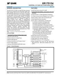
17D154 UART DATA SHEET ................................................................................................... 17<br />
Fast<strong>com</strong> ® : <strong>422</strong>/4-<strong>PCI</strong>-<strong>335</strong>
1<br />
EUROPEAN UNION DECLARATION OF CONFORMITY<br />
Information Technology Equipment<br />
The Company COMMTECH, INC. declares under its own and full responsibility that the product<br />
" Fast<strong>com</strong> <strong>422</strong>/4-<strong>PCI</strong>-<strong>335</strong> - Revision 1.3 "<br />
on which is attached this Certificate is <strong>com</strong>pliant to the "89/336/EEC" Directive, amended by 92/31/EEC and<br />
93/88/EEC.<br />
[ ] The product identified above <strong>com</strong>plies with the requirements of the above EU Directive by meeting the<br />
following standards:<br />
• EN 50081-1 (1992) EMC Generic Emission Standard - Part 1, Residential, Commercial and Light Industry<br />
- EN 55022 (1995), CISPR 22 (1993) Limits and Methods of Measurement of Radio Disturbance<br />
Characteristics of Information Technology Equipment, 30 MHz - 1 GHz, Class B Limits<br />
• EN 50082-1 (1992) EMC Generic Immunity Standard - Part 1, Residential, Commercial and Light Industry<br />
- IEC 801-2 (1984), Method of Evaluating Susceptibility to Electrostatic Discharge, Level 4<br />
- IEC 801-3 (1984), Radiated Electromagnetic field Requirements, Level 3<br />
- IEC 801-4 (1988), Electrical Fast Transient/Burst Requirements, Level 2<br />
Products listed on this declaration are exempt from the requirements of the 73/23/EEC directive due to the input<br />
voltage specification as stated in Article 1 of the directive.<br />
The technical documentation required to demonstrate that this product meets the requirements of the EMC<br />
Directive has been <strong>com</strong>piled by the signatory below and is available for inspection by the relevant enforcement<br />
authorities.<br />
In WICHITA, KS on April 1st of 2011<br />
9011 E. 37th Street North<br />
Wichita, KS 67226-2006<br />
(316) 636-1131<br />
Fax (316) 636-1163<br />
Mr. Glen R. Alvis<br />
Chief Engineer<br />
Fast<strong>com</strong> ® : <strong>422</strong>/4-<strong>PCI</strong>-<strong>335</strong>
2<br />
Fast<strong>com</strong> ® : <strong>422</strong>/4-<strong>PCI</strong>-<strong>335</strong>
3<br />
INTRODUCTION<br />
The new Fast<strong>com</strong> Universal <strong>PCI</strong> Bus, Asynchronous RS<strong>422</strong>/485 adapter utilizes the latest technology to live up to<br />
today’s requirements for high bandwidth requirements in <strong>com</strong>munication systems. The new Fast<strong>com</strong>: <strong>422</strong>/4-<strong>PCI</strong>-<br />
<strong>335</strong> is capable of operating at virtually any baud rate up to an astounding maximum serial data rate of 6.25 Mbps.<br />
There is no fine print or asterisks pointing to notes; this card is capable of running at the maximum data rate,<br />
without any jumpers or hardware changes, right out of the box.<br />
Designed to <strong>com</strong>ply with the latest <strong>PCI</strong> specifications, the Universal <strong>PCI</strong> adapter will operate in both 5V and 3.3V<br />
<strong>PCI</strong> slots. This means the card will work in the high speed <strong>PCI</strong>-X slots that <strong>com</strong>monly found in most new servers<br />
as well as the standard <strong>PCI</strong> slots in desktop PC’s. This flexibility allows for a single serial interface board to be<br />
used across a wide range of different types of <strong>com</strong>puters including both current and future <strong>com</strong>puting systems.<br />
The Fast<strong>com</strong>: <strong>422</strong>/4-<strong>PCI</strong>-<strong>335</strong> adapter utilizes an advanced quad Universal Asynchronous Receiver and<br />
Transmitter (UART). Each channel of the 17D154 UART is independently controlled and has its own 16C550<br />
<strong>com</strong>patible register set. Each UART contains its own receive and transmit FIFOs of 64 bytes with programmable<br />
trigger levels.<br />
Each of the four UART channels on the board can be independently configured as either RS-<strong>422</strong> or RS-485 for<br />
full or half-duplex <strong>com</strong>munication. This is implemented using an automatic RS-485 transmitter enable/disable<br />
function that permits the hardware itself to regulate data flow by only driving lines while actively transmitting. This<br />
provides increased speed and convenience over the older software controlled method, while still allowing the use<br />
of the software method of flow control. Optionally, in automatic RS-485 mode, the receiver can be disabled<br />
during transmits to avoid a receive echo, <strong>com</strong>mon in 2-wire 485 networks.<br />
Additionally, each board utilizes a programmable clock generator to create the UARTs input frequency. The clock<br />
generator is capable of generating frequencies between 6 and 50 MHz. Utilizing this feature, it is possible to<br />
configure the board to operate at virtually any serial data rate that the user desires (up to 6.25 Mbits/second<br />
maximum).<br />
With the supplied software driver, the ports on the Fast<strong>com</strong>: <strong>422</strong>/4-<strong>PCI</strong>-<strong>335</strong> will be seen as standard COM ports<br />
and can utilize all the same functions as a standard serial device. With the addition of a few simple IO <strong>com</strong>mands<br />
to control the unique features of the board, the standard software interface to a serial port can be used to simplify<br />
program design. Example C programs are provided to demonstrate how to effectively use serial interface as well<br />
as control the board specific features.<br />
Overall, the new Fast<strong>com</strong>: <strong>422</strong>/4-<strong>PCI</strong>-<strong>335</strong> Universal <strong>PCI</strong> Bus RS-<strong>422</strong>/485 adapter is the ideal board for<br />
<strong>com</strong>mercial and industrial applications demanding high data rates, reliability and ease of use.<br />
Software drivers for Windows 2000/XP and Linux are supplied. Multiple Fast<strong>com</strong>: <strong>422</strong>/4-<strong>PCI</strong>-<strong>335</strong> adapters can be<br />
installed in all operating systems.<br />
Fast<strong>com</strong> ® : <strong>422</strong>/4-<strong>PCI</strong>-<strong>335</strong>
4<br />
Specifications<br />
UART:<br />
OS Support:<br />
Data Rates:<br />
Buffering:<br />
Drivers/Receivers:<br />
Interface:<br />
Signals:<br />
Connector Configuration:<br />
Exar 17D154<br />
Windows XP, 2000, Linux<br />
All baud rates up to 6.25Mbit/s<br />
64 byte Tx FIFO each channel<br />
64 byte Rx FIFO each channel<br />
High Speed RS-<strong>422</strong><br />
RS-<strong>422</strong> / RS-485<br />
Tx , Rx , RTS , CTS<br />
DB37 male to 4 DB9 female<br />
Bus Interface: 32-bit <strong>PCI</strong> Version 2.3<br />
Power Requirements:<br />
Certification:<br />
Operating Temperature Range:<br />
Humidity:<br />
600mA @ +5V (typical)<br />
FCC <strong>com</strong>pliant, CE marked<br />
0 C to 70 C<br />
0 to 90% (non-condensing)<br />
Features<br />
New high performance UART<br />
‣ Standard or the Fast<strong>com</strong>: <strong>422</strong>/4-<strong>PCI</strong>-<strong>335</strong><br />
‣ All baud rates up to 6.25 Mbits/sec<br />
‣ 64 byte FIFO for improved throughput<br />
‣ Four independent channels<br />
‣ Hardware control for 485 drivers<br />
Software programmable baud rates<br />
Switchless design for durability and reliability<br />
Status LED’s for system development / debugging<br />
Hardware Rx echo cancel available in RS485 mode<br />
Durable cables with RFI shielding<br />
Hardware documentation, software, and example programs provided on the Fast<strong>com</strong> CD<br />
Made in Wichita, Kansas USA<br />
Fast<strong>com</strong> ® : <strong>422</strong>/4-<strong>PCI</strong>-<strong>335</strong>
5<br />
BOARD LAYOUT<br />
4721 mils<br />
Dimensions<br />
4200 mils<br />
Status LED’s<br />
Rx = Yellow<br />
Tx = Red<br />
DB37 Connector<br />
Universal 32-Bit <strong>PCI</strong> BUS<br />
PACKING LIST<br />
Fast<strong>com</strong>: <strong>422</strong>/4-<strong>PCI</strong>-<strong>335</strong> Card<br />
<strong>422</strong>/4 Cable Assembly<br />
Fast<strong>com</strong> CD<br />
If an omission has been made, please call customer service at 316-636-1131 for a replacement.<br />
Fast<strong>com</strong> ® : <strong>422</strong>/4-<strong>PCI</strong>-<strong>335</strong>
6<br />
INSTALLATION<br />
Hardware Installation<br />
Important: Static electricity can harm system boards. Perform service at an ESD workstation and follow<br />
proper ESD procedure to reduce the risk of damage to <strong>com</strong>ponents. <strong>Commtech</strong>, Inc. strongly encourages<br />
you to follow proper ESD procedure, which can include wrist straps and smocks, when handling<br />
Fast<strong>com</strong>: <strong>422</strong>/4-<strong>PCI</strong>-<strong>335</strong> boards.<br />
1. Turn off PC power. Disconnect the power cord.<br />
2. Remove the PC case cover (if applicable).<br />
3. Unpack the Fast<strong>com</strong>: <strong>422</strong>/4-<strong>PCI</strong>-<strong>335</strong>. Keep the box and static bag for warranty repair returns.<br />
4. Select an open <strong>PCI</strong> slot in your PC.<br />
5. After removing the blank bracket from your PC, install the Fast<strong>com</strong>: <strong>422</strong>/4-<strong>PCI</strong>-<strong>335</strong> in the PC by pressing<br />
it firmly into the slot. Install the bracket screw to hold it firmly in place.<br />
6. Re-install the cover on your PC.<br />
7. Refer to Software Installation in the next section for information on installing the software for the board.<br />
Software Installation<br />
1. Click here to open the Installation Manual located on your Fast<strong>com</strong> CD. If you do not have the Fast<strong>com</strong><br />
CD, you can click here to download the installation manual from our web site.<br />
2. Find Fast<strong>com</strong>-Async-<strong>PCI</strong>-<strong>335</strong> series cards select your operating system and follow the instructions to<br />
install the software for your board.<br />
3. When you are finished, select Fast<strong>com</strong>: <strong>422</strong>/4-<strong>PCI</strong>-<strong>335</strong> from the list at the end of the Fast<strong>com</strong>-Async-<strong>PCI</strong><br />
series section to return to this manual.<br />
TESTING THE INSTALLATION<br />
To fully test the installation of your Fast<strong>com</strong>: <strong>422</strong>/4-<strong>PCI</strong>-<strong>335</strong>, you will need to build a "loop back plug". Materials<br />
needed are a DB9 male plug, solder cup style, and two short pieces of 20 or 24 AWG stranded wire. This loop<br />
back plug can be used to test any RS-<strong>422</strong> port. Jumper the pins together on the DB9 as illustrated below:<br />
Pin 4 Tx+<br />
Pin 5 Tx -<br />
Pin 8 Rx+<br />
Pin 9 Rx-<br />
4<br />
5<br />
8<br />
9<br />
Fast<strong>com</strong> ® : <strong>422</strong>/4-<strong>PCI</strong>-<strong>335</strong>
7<br />
Testing the Fast<strong>com</strong> Async <strong>PCI</strong> Port in Windows<br />
These instructions assume that you have already installed the card and have followed the installation instructions.<br />
The Device Manager should show the boards/ports that are installed, and the COM numbers assigned to those<br />
ports.<br />
1. Attach the supplied <strong>422</strong>/4 Cable Assembly to the DB37 connector. Install the loopback plug on the port to<br />
test.<br />
2. Open an MS-DOS or Command prompt windows and change to the directory (C:\> cd<br />
directoryname ) where you saved the Fast<strong>com</strong> software files that were either copied from the CD or<br />
downloaded from our website. Change to the examples directory, then change to the loop_back<br />
directory.<br />
3. Type: loop_back X Where X is the COM port you wish to test.<br />
4. This test will transmit data out of the specified COM port and receive the data on the same port, checking<br />
to see that the data is still the same.<br />
If you get error messages during the loop_back test, some possible reasons are:<br />
1. You have an incorrect or faulty loop back plug construction or a bad connection. Verify that the wiring is<br />
correct in your plug and correct any problems you may find.<br />
2. The Fast<strong>com</strong> board did not install correctly. Open the Device Manager (Start -> Run -> devmgmt.msc -><br />
OK). Expand the “Multiport Serial Adapter” tab and double click on the Fast<strong>com</strong> device listed in that<br />
class. Verify that the Device Status box on the General class lists “The device is working properly.”<br />
3. The Fast<strong>com</strong> ports did not install correctly. Open the Device Manager (Start -> Run -> devmgmt.msc -><br />
OK). Expand the “Ports (COM & LPT)” class and double click on the Fast<strong>com</strong> ports listed in that class.<br />
Verify that the Device Status box on the General tab lists “The device is working properly.”<br />
4. The loop back plug is not connected to the correct port/cable.<br />
Fast<strong>com</strong> ® : <strong>422</strong>/4-<strong>PCI</strong>-<strong>335</strong>
8<br />
FASTCOM ASYNC<strong>PCI</strong>-<strong>335</strong> SERIAL SETTINGS<br />
The Serial Settings property page can be found by opening the Device Manager (Start -> Run -> devmgmt.msc -><br />
OK), expanding the “Ports (COM & LPT)” class and double clicking on one of the installed “Fast<strong>com</strong> Async<strong>335</strong><br />
Communications Port” devices, and then clicking on the “Fast<strong>com</strong> Async<strong>PCI</strong>-<strong>335</strong> Serial Settings” tab.<br />
Each port on the Fast<strong>com</strong> board has all of the settings available to it. However there are two options that will<br />
affect all other ports on that particular Fast<strong>com</strong> board: Clock Generator Frequency and Rx Echo Cancel. All<br />
other settings are will affect only the selected port.<br />
Clicking on each individual setting will bring up a description of the setting in box at the top of the page. This is a<br />
slightly more detailed version of those same descriptions.<br />
Clock Generator Frequency<br />
The clock generator frequency divided by the sampling rate will directly determine the maximum available<br />
bit rate that you may use with the Fast<strong>com</strong> board. It works like this: Windows must be able to divide the<br />
clock frequency by the sampling rate and then by any whole number and get to your bit rate as the<br />
answer. By default, the clock is set to 14.7456 MHz (14745600 Hz). This frequency can be divided by<br />
whole numbers to get all of the standard bit rates (i.e. 9600, 19200, 115200, etc). Minimum = 6 MHz,<br />
Maximum = 50 MHz.<br />
For Example:<br />
Frequency / Sampling rate (8 or 16) / n = bit rate<br />
14,745,600 / 16 / 96 = 9600<br />
This setting is global. Changing the clock generator frequency will affect all Fast<strong>com</strong> ports on the board.<br />
Setting the clock for one port will set it for all port of the same board.<br />
Rx Echo Cancel<br />
When configured to operate on a 485 network, the card’s receive and transmit lines are tied together to<br />
make a single data line. Because of this, every time data is transmitted out of the port, it will<br />
simultaneously be received on the same port. Enabling Rx Echo Cancel will turn off the receiver during<br />
all transmits, eliminating this simultaneous echo. 485 transmit control must be enabled to use this<br />
feature. This is ac<strong>com</strong>plished in hardware not software; it will not affect performance.<br />
This setting is global. Enabling or disabling this option will affect all other ports on the board.<br />
Sampling Rate<br />
Determines the number of times a data bit is sampled. It can be set to either 8 or 16 on a per port basis.<br />
It is used in conjunction with clock generator frequency to determine attainable bit rates. As a general<br />
rule, if your bit rate will be less than or equal to 3.125 Mbits/sec you should use 16 times sampling. 8<br />
times sampling should only be used if you wish to run at bit rates over 3.125 Mbits/sec.<br />
Max Baud<br />
This field reads the values that you have entered in the clock generator box and the sampling box and<br />
calculates the maximum bit rate possible using those settings. The formula used to calculate the<br />
maximum bit rate looks like this:<br />
Frequency / Sampling = Maximum bit rate<br />
Or<br />
Frequency / Sampling rate (8 or 16) / 1 = Max bit rate<br />
Fast<strong>com</strong> ® : <strong>422</strong>/4-<strong>PCI</strong>-<strong>335</strong>
9<br />
Hardware Auto 485<br />
Turns on or off hardware auto 485 direction control. It will automatically de-assert RTS following the last<br />
stop bit of the last character that has been transmitted. This setting affects only the selected port. This is<br />
ac<strong>com</strong>plished in hardware not software; it will not affect performance.<br />
485 Transmit Control<br />
Turns on or off auto 485 transmitter enable control. The line driver will be enabled at the beginning of a<br />
transmit, and when finished transmitting the line driver will be disabled. Must enable Hardware Auto 485<br />
to use this feature. This setting affects only the selected port. This is ac<strong>com</strong>plished in hardware not<br />
software; it will not affect performance.<br />
Rx FIFO Trigger Level 1<br />
The Rx FIFO level generates an interrupt whenever the receive FIFO level rises above this preset trigger<br />
level (high water mark). Raising or lowering this value can help to reduce the number of interrupts<br />
generated by the Fast<strong>com</strong> port during receives. This setting affects only the selected port. Modify this<br />
value only if necessary in your application or if the receiver is generating too many interrupts for your<br />
CPU to handle.<br />
Tx FIFO Trigger Level 1<br />
The Tx FIFO level generates an interrupt whenever the transmit FIFO level falls below this preset trigger<br />
level (low water mark). Raising or lowering this value can help to reduce the number of interrupts<br />
generated by the Fast<strong>com</strong> port during transmits. This setting affects only the selected port. Modify this<br />
value only if necessary in your application or if the transmitter is generating too many interrupts for your<br />
CPU to handle. Tx FIFO Trigger + Tx Write Size must not exceed 64.<br />
Tx Write Size 1<br />
Tx Write Size is the number of bytes that get written to the Tx FIFO when the low water mark is reached.<br />
Raising or lowering this value can help to reduce the number of interrupts generated by the Fast<strong>com</strong> port<br />
during transmits. This setting affects only the selected port. Modify this value only if necessary in your<br />
application or if the transmitter is generating too many interrupts for your CPU to handle. Tx FIFO Trigger<br />
+ Tx Write Size must not exceed 64.<br />
Software 9-Bit Mode<br />
Turns on or off software 9-bit mode emulation. A feature of some UARTS and microcontrollers "MCS-51<br />
9-bit format.” If you don't know what this is, you probably do not want to use it.<br />
Return 9-Bit data<br />
Turns on or off the returning of the 9th data bit as its own character. A feature of some UARTS and<br />
microcontrollers "MCS-51 9-bit format." If you don't know what this is, you probably do not want to use it.<br />
Custom Speed<br />
When enabled, this allows you to use a non-standard, custom baud rate inside of an application that does<br />
not support custom rates. When this is enabled, the 9600 baud rate will be overridden with the Max Baud<br />
rate. Just select a baud rate of 9600 in your application and you will get whatever rate you have in the<br />
Max Baud field.<br />
1 The results of changing the Rx FIFO Trigger, Tx FIFO Trigger, and Tx Write Size will depend entirely upon the<br />
host PC. What lowers the number of interrupt requests on one PC will raise the number of interrupt requests on<br />
another PC. You will have to experiment with these values to find the settings that yield the best performance<br />
with the lowest number of interrupt requests that must be serviced by your CPU. If you do not experience<br />
problems using the card in you PC, you should leave these at their default settings.<br />
Fast<strong>com</strong> ® : <strong>422</strong>/4-<strong>PCI</strong>-<strong>335</strong>
10<br />
Fast<strong>com</strong> ® : <strong>422</strong>/4-<strong>PCI</strong>-<strong>335</strong>
11<br />
FASTCOM: <strong>422</strong>/4-<strong>PCI</strong>-<strong>335</strong> ADAPTER CABLE<br />
We provide access to the four channels of the FASTCOM: <strong>422</strong>/4-<strong>PCI</strong>-<strong>335</strong> through a shielded DB37 connector<br />
and an adapter cable (supplied with the board). The adapter cable consists of a DB37 male plug fanning out to<br />
four standard DB9 female receptacles.<br />
DB37 Pin Description<br />
DB9 Pin Description<br />
The FASTCOM: <strong>422</strong>/4-<strong>PCI</strong>-<strong>335</strong> features four RS-<strong>422</strong>/RS-485 channels, which<br />
are accessed through four DB9 connectors on the cable assembly.<br />
The following is a pin description of the DB9 connectors:<br />
N.C<br />
RTS-4<br />
GND<br />
RX-4<br />
TX-4<br />
CTS-3<br />
CTS+3<br />
RTS+3<br />
RX+3<br />
TX+3<br />
RTS-2<br />
GND<br />
RX-2<br />
TX-2<br />
CTS-1<br />
CTS+1<br />
RTS+1<br />
RX+1<br />
TX+1<br />
1<br />
2<br />
3<br />
4<br />
5<br />
6<br />
7<br />
8<br />
9<br />
10<br />
11<br />
12<br />
13<br />
14<br />
15<br />
16<br />
17<br />
18<br />
19<br />
20<br />
21<br />
22<br />
23<br />
24<br />
25<br />
26<br />
27<br />
28<br />
29<br />
30<br />
31<br />
32<br />
33<br />
34<br />
35<br />
36<br />
37<br />
CTS-4<br />
CTS+4<br />
RTS+4<br />
RX+4<br />
TX+4<br />
RTS-3<br />
GND<br />
RX-3<br />
TX-3<br />
CTS-2<br />
CTS+2<br />
RTS+2<br />
RX+2<br />
TX+2<br />
RTS-1<br />
GND<br />
RX-1<br />
TX-1<br />
PIN NO. SIGNAL NAME DIRECTION<br />
1 SIGNAL GROUND (GND) GROUND<br />
2 READY TO SEND (RTS) + OUTPUT<br />
3 READY TO SEND (RTS) – OUTPUT<br />
4 TRANSMIT DATA (TX) + OUTPUT<br />
5 TRANSMIT DATA (TX) – OUTPUT<br />
6 CLEAR TO SEND (CTS) + INPUT<br />
7 CLEAR TO SEND (CTS) - INPUT<br />
8 RECEIVE DATA (RX) + INPUT<br />
9 RECEIVE DATA (RX) – INPUT<br />
GND<br />
RTS+<br />
RTS-<br />
TX+<br />
TX-<br />
1<br />
2<br />
3<br />
4<br />
5<br />
6<br />
7<br />
8<br />
9<br />
CTS+<br />
CTS-<br />
RX+<br />
RX-<br />
Cable<br />
We re<strong>com</strong>mend using vinyl jacketed, shielded, multiple twisted pair cable (24 AWG<br />
wire) for use with the FASTCOM: <strong>422</strong>/4-<strong>PCI</strong>-<strong>335</strong>. The following cable illustration<br />
shows how to connect two RS-<strong>422</strong> devices. Note that disabling handshaking can<br />
eliminate CTS/RTS lines.<br />
TX+<br />
TX-<br />
RX+<br />
RX-<br />
GND<br />
RTS+<br />
RTS-<br />
CTS+<br />
CTS-<br />
TX+<br />
TX-<br />
RX+<br />
RX-<br />
GND<br />
RTS+<br />
RTS-<br />
CTS+<br />
CTS-<br />
Fast<strong>com</strong> ® : <strong>422</strong>/4-<strong>PCI</strong>-<strong>335</strong>
12<br />
PROGRAMMING<br />
To interface with the serial ports on the Fast<strong>com</strong>: <strong>422</strong>/4-<strong>PCI</strong>-<strong>335</strong> in a Windows application, your code will use the<br />
standard Win32 COM API. Documentation pertaining to how to use the Win32 API is beyond the scope of this<br />
document. For more information on using the API, refer to the “Using Communications Resources” in the MSDN.<br />
In addition to the Win32 API, you can also use several special Fast<strong>com</strong> specific <strong>com</strong>mands that allow you to<br />
ac<strong>com</strong>plish all of the options from the Fast<strong>com</strong> Async<strong>PCI</strong>-<strong>335</strong> Serial Settings property page. These <strong>com</strong>mands<br />
as well as the custom structures used in them are defined in the fcapi.h header file.<br />
Fast<strong>com</strong> Async<strong>PCI</strong>-<strong>335</strong> Serial Setting DeviceIOControl dwIoControlCode<br />
Clock Generator Frequency<br />
IOCTL_FASTCOM_SET_CLOCK<br />
Rx Echo Cancel<br />
IOCTL_FASTCOM_SET_RXECHO<br />
Sampling Rate<br />
IOCTL_FCPORT_SET_SAMPLING<br />
Hardware Auto 485<br />
IOCTL_FCPORT_SET_RS485<br />
485 Transmit Control IOCTL_FCPORT_SET_485_TXEN<br />
Tx FIFO Trigger Level<br />
IOCTL_FCPORT_SET_RXTX_TRIG<br />
Tx FIFO Trigger Level<br />
IOCTL_FCPORT_SET_RXTX_TRIG<br />
Tx Write Size<br />
IOCTL_FCPORT_SET_RXTX_TRIG<br />
Refer to the Async<strong>PCI</strong><strong>335</strong>\examples directory on the Fast<strong>com</strong> CD or in the downloaded zip file for some example<br />
C programs that demonstrate how to use the Fast<strong>com</strong> specific serial settings as well as give a general sense of<br />
how to use the Win32 API.<br />
Fast<strong>com</strong> ® : <strong>422</strong>/4-<strong>PCI</strong>-<strong>335</strong>
13<br />
RS<strong>422</strong> / RS485<br />
Most engineers have worked with RS-232 devices at least once in their career. If you have never worked with<br />
RS-<strong>422</strong> or RS-485 devices, you will be pleased to know that working with the FASTCOM: <strong>422</strong>/4-<strong>PCI</strong>-<strong>335</strong> is not<br />
much different from working with a standard RS-232 device.<br />
The RS-<strong>422</strong> standard was developed to correct some of the deficiencies of RS-232. In <strong>com</strong>mercial and industrial<br />
applications, RS-232 has some significant problems. First, the cable length between RS-232 devices must be<br />
short (usually less than 50 feet at 9600 baud). Second, many RS-232 errors are the result of cables picking up<br />
normal industrial electrical noises such as fluorescent lights, motors, transformers, and other EMF sources. Third,<br />
RS-232 data rates are functionally limited to 19.2K Baud. On the other hand, the newer RS-<strong>422</strong> standard makes<br />
cable lengths up to 5000 feet possible and is highly immune to most industrial noises. Data rates are also<br />
improved -- the FASTCOM: <strong>422</strong>/4-<strong>PCI</strong>-<strong>335</strong> features data rates up to 6.25 Mbit/sec. These improvements were<br />
made possible by differentially driving and receiving the data as opposed to the single ended method employed<br />
by the RS-232 standard. With the RS-<strong>422</strong> standard, the transmit signal (TX in RS-232) is a differential signal<br />
consisting of TX+ and TX-; the receive signal (RX in RS-232) consists of RX+ and RX-.<br />
Another draw back of RS-232 is that more than two devices cannot share a single cable. This is also true of<br />
RS-<strong>422</strong>, and that's why the RS-485 standard was developed. RS-485 offers all of the benefits of RS-<strong>422</strong> and<br />
also allows multiple units (up to 32) to share the same “twisted pair” of wires (see diagram on next page). RS-485<br />
is often referred to as a "multi-drop" or "two-wire, half duplex" network. In order for an RS-485 system to work,<br />
only one driver (transmitter) can occupy the network at a time. This means that each station on the network must<br />
control the enabling/disabling of their drivers in order to avoid network conflicts. If two drivers engage the network<br />
at the same time, data from both will be corrupted. In RS-485 mode, the receivers are always enabled.<br />
For a more detailed description of RS-<strong>422</strong> and RS-485, we re<strong>com</strong>mend the following references:<br />
LINEAR AND INTERFACE CIRCUITS APPLICATIONS, Volume 2: Line Circuits, Display Drivers. By<br />
D.E. Pippenger and E. J. Tobaben. Published 1985 by Texas Instruments. ISBN-0-89512-185-9<br />
Note: This book may be difficult to find in a bookstore. The best place to get it is directly from Texas<br />
Instruments or from one their <strong>com</strong>ponent dealers. Publication # SLYA002.<br />
"Driver/Receiver Family Extends Data-Link Performance", ELECTRONIC PRODUCTS, January 15, 1985.<br />
By Dale Pippenger and Joe Miller<br />
Fast<strong>com</strong> ® : <strong>422</strong>/4-<strong>PCI</strong>-<strong>335</strong>
14<br />
Termination Resistance<br />
In both the RS-<strong>422</strong> and the RS-485 mode, the receiver end of the cable between two stations must be terminated<br />
with a resistor equal to the characteristic impedance of the wire. This is to prevent signal reflections in the wire<br />
and to improve noise rejection. However, you do not need to add a terminator resistor to your cables when<br />
you use the Fast<strong>com</strong>: <strong>422</strong>/4-<strong>PCI</strong>-<strong>335</strong>. The termination resistance is built in. We have installed a terminator<br />
resistor for each receiver: between RX+ and RX- and between CTS+ and CTS- for each channel.<br />
If you are using the Fast<strong>com</strong>: <strong>422</strong>/4-<strong>PCI</strong>-<strong>335</strong> in a multi-drop network, the termination resistor should be removed<br />
from all units except the first and last (see the RS-485 illustration below). Call for technical support if you need to<br />
modify the resistor. You may also order the Fast<strong>com</strong>: <strong>422</strong>/4-<strong>PCI</strong>-<strong>335</strong> without the termination resistor installed (it<br />
is easier to add the resistor than to remove it). Observe the resistors in the following drawings and remember that<br />
they are built into the Fast<strong>com</strong>: <strong>422</strong>/4-<strong>PCI</strong>-<strong>335</strong> (shown below):<br />
TX<br />
Typical RS-<strong>422</strong> Installation<br />
TX+<br />
1 2<br />
RX<br />
RX+<br />
R1<br />
R2<br />
RX+<br />
TX-<br />
RX-<br />
RX-<br />
TX+<br />
TX-<br />
RX<br />
TX<br />
R1 & R2 - Line Termination (100 ohms)<br />
Typical RS-485 Installation<br />
1<br />
TX<br />
TX+<br />
TX-<br />
R1<br />
R2<br />
RX+<br />
RX-<br />
RX<br />
4<br />
RX<br />
RX+<br />
RX-<br />
TX+<br />
TX-<br />
TX<br />
2<br />
TX<br />
RX<br />
TX+<br />
TX-<br />
RX+<br />
RX-<br />
RX+<br />
RX-<br />
TX+<br />
TX-<br />
RX<br />
TX<br />
3<br />
R1 & R2 - Line Termination (100 ohms)<br />
Fast<strong>com</strong> ® : <strong>422</strong>/4-<strong>PCI</strong>-<strong>335</strong>
15<br />
RS-485 Mode<br />
RS-485 is often referred to as a multi-drop or two-wire, half duplex network because the drivers (transmitters) and<br />
receivers share the same two lines. In fact, up to 32 stations can share the same twisted pair. In order for an<br />
RS-485 system to work, only one driver (transmitter) can occupy the network at a time. This means that each<br />
station on the network must control the enabling/disabling of its drivers in order to avoid network conflicts. If two<br />
drivers engage the network at the same time, data from both will be corrupted. In RS-485 mode, the receivers<br />
are always enabled.<br />
The following cable illustration shows four RS-485 Devices sharing the same twisted pair:<br />
TX+<br />
TX-<br />
TX+<br />
TX+<br />
TX+<br />
TX- TX- TX-<br />
RX+<br />
RX -<br />
RX+ RX + RX +<br />
RX - RX - RX -<br />
1 2 3 4<br />
Note: The termination resistors from Station #2 and Station #3 have been removed.<br />
Not all RS-<strong>422</strong> devices feature RS-485 <strong>com</strong>patibility; only RS-485 devices can be connected to the RS-485<br />
network.<br />
DB9 MALE<br />
4 TX +<br />
5 TX -<br />
8 RX +<br />
9 RX -<br />
5<br />
4<br />
9<br />
8<br />
-<br />
+<br />
To RS-485 Network<br />
Note that when in the RS-485 mode, you will need to externally connect TX+ to RX+ and TX- to RX-.<br />
Fast<strong>com</strong> ® : <strong>422</strong>/4-<strong>PCI</strong>-<strong>335</strong>
16<br />
TECHNICAL SUPPORT<br />
<strong>Commtech</strong> provides extensive technical support and application suggestions. Most of the problems that occur<br />
with the FASTCOM: <strong>422</strong>/4-<strong>PCI</strong>-<strong>335</strong> can be corrected by double-checking the switch positions, your cables and<br />
your program. We re<strong>com</strong>mend that you build the loop back plug that is described in the Programming section of<br />
this manual. With that plug, you can quickly isolate the problem to the board, cables, or software.<br />
If you still have unresolved questions, use the following procedure to get technical support:<br />
1. Call our Technical Support Staff at (316) 636-1131. They are on duty from 9:00 AM to 5:00 PM Central Time.<br />
2. Ask for technical support for the FASTCOM: <strong>422</strong>/4-<strong>PCI</strong>-<strong>335</strong>. Be ready to describe the problem, your<br />
<strong>com</strong>puter system, your application, and your software.<br />
3. If necessary, our staff will give you an RMA number (Return Material Authorization). Use this number on the<br />
mailing label and in all references to your board. Put the board back in its static bag and in its box. Ship the<br />
board back to us as directed.<br />
4. If you prefer, you may FAX a description of the problem to us at (316) 636-1163, or we can be reached on the<br />
Internet at http://www.<strong>com</strong>mtech-<strong>fast<strong>com</strong></strong>.<strong>com</strong>/TechSupport.html or by email at techsupport@<strong>com</strong>mtech<strong>fast<strong>com</strong></strong>.<strong>com</strong>.<br />
FASTCOM LIMITED LIFETIME WARRANTY<br />
<strong>Commtech</strong>’s entire FASTCOM product line is covered by a limited lifetime warranty against defects in workmanship. This<br />
warranty is available only to the original purchaser and only covers defects in our workmanship. Any FASTCOM board that is<br />
returned to <strong>Commtech</strong> will, at the option of <strong>Commtech</strong>, be repaired or replaced at no charge -- except for circumstances<br />
excluded by this warranty.<br />
A Return Materials Authorization (RMA) number must be obtained from <strong>Commtech</strong> before a return will be accepted. Please<br />
contact us via telephone or email to obtain an RMA number.<br />
You are responsible for shipping charges when you return a FASTCOM board to <strong>Commtech</strong>. We will pay the shipping<br />
charges to send the board back to you if a defect in workmanship is found. However, if no defect in workmanship is found, or<br />
the board is not found to be defective, or the any of the following warranty exclusions occur, you will be responsible for<br />
shipping charges both ways.<br />
Warranty Exclusions<br />
This warranty does not cover problems or damage resulting from, but not limited to, the following:<br />
1. Any modification, misuse, abuse, disassembly, misapplication, or unauthorized repair by anyone other than<br />
<strong>Commtech</strong>.<br />
2. Any improper operation, including any use not in accordance with any verbal product instructions or documentation.<br />
3. Connection to an improper voltage supply or ESD damage.<br />
4. Any other cause not related to workmanship.<br />
Non-Warranty Repairs<br />
We can provide a quote for non-warranty repairs upon request.<br />
If any <strong>Commtech</strong> product is damaged such that it cannot be repaired, you can return it to <strong>Commtech</strong> for replacement under<br />
our Non-Repairable Replacement policy, regardless of the cause of damage. <strong>Commtech</strong> will replace the unit at 60% of the<br />
then-current list price.<br />
Limitation of Liability<br />
<strong>Commtech</strong> shall not be liable for any special, incidental, indirect, or consequential damages whatsoever, including but not<br />
limited to loss of profits, revenue, or data (whether direct or indirect), or <strong>com</strong>mercial loss for breach of any express or implied<br />
warranty on your product even if <strong>Commtech</strong> has been advised previously of the possibility of such damages. <strong>Commtech</strong> does<br />
not warrant that its products will work in every system or every system configuration. We do not warrant that our products will<br />
be suitable for your application. If you are dissatisfied with our product, contact customer service to arrange for a return of our<br />
product and refund of your money. <strong>Commtech</strong>’s liability, in any case, is limited to the original product purchase price and is<br />
available to the original customer only.<br />
Fast<strong>com</strong> ® : <strong>422</strong>/4-<strong>PCI</strong>-<strong>335</strong>
17<br />
APPENDIX A<br />
17D154 UART<br />
Data Sheet<br />
View from CD<br />
Download from web<br />
Fast<strong>com</strong> ® : <strong>422</strong>/4-<strong>PCI</strong>-<strong>335</strong>