BW 585 - Kendan
BW 585 - Kendan
BW 585 - Kendan

Create successful ePaper yourself
Turn your PDF publications into a flip-book with our unique Google optimized e-Paper software.
Biegler<br />
Blood and Infusion Warmer<br />
Manufacture, Assembly and<br />
Test Documentation<br />
<strong>BW</strong> <strong>585</strong><br />
PCB Version <strong>BW</strong> <strong>585</strong> V1.6<br />
Software V 1.2<br />
November, 2007<br />
<strong>BW</strong> Manufacture, Assembly, Test Documentation
Contents<br />
1. Technical Data 3<br />
2. Notes for the User 4<br />
3. Safety Cut-off 5<br />
4. Temperature Adjustment 7<br />
5. Assembly and Dismantling 10<br />
6. Inspection Instructions 13<br />
7. Test Records for <strong>BW</strong> <strong>585</strong> 19<br />
8. Safety Checks 20<br />
9. Electrical Safety 22<br />
10. Parts Lists 24<br />
11. Exploded Drawing and<br />
Component Mounting Diagrams<br />
Page 2 <strong>BW</strong> Manufacture, Assembly, Test Documentation November, 2007
1. Technical Data<br />
Technical Data - <strong>BW</strong> <strong>585</strong><br />
Model <strong>BW</strong> <strong>585</strong><br />
Voltage<br />
230 VAC / 110 VAC<br />
Frequency<br />
50 Hz<br />
Power consumption<br />
300 W<br />
Preheating time<br />
max. 60 sec<br />
Operating temp. 37 - 41°C<br />
Safety cut-off<br />
three-fold<br />
Moisture resistance<br />
IPX4<br />
Protection class<br />
I<br />
Protection grade<br />
B<br />
Dimensions<br />
140 x 190 x 230 mm<br />
Weight<br />
2,0 kg<br />
Fuses 230VAC 1,6A slow (primary)<br />
0,315A slow (secondary)<br />
110 VAC 3,15A slow (primary)<br />
0,315A slow (secondary)<br />
November, 2007 <strong>BW</strong> Manufacture, Assembly, Test Documentation Page 3
2. Notes for the User<br />
Manufacturer’s Responsibility<br />
Biegler or the Company’s authorised dealers shall only be responsible for the equipment’s<br />
safety, reliability and performance if:<br />
• the operating instructions are adhered to during use<br />
• the electrical installations in the room where the equipment is used meet the statutory<br />
technical requirements<br />
• modifications, repairs or adjustments are or were carried out solely by Biegler or<br />
authorised personnel<br />
• only original Biegler spare parts are used for repairs (also applies to power supply cable).<br />
If the buzzer or red warning light comes on, remove the infusion or transfusion tube from the<br />
heating element and disconnect the connection tube to the patient immediately .<br />
WARRANTY<br />
Biegler Medizinelektronik guarantees this device against material and manufacturing defects<br />
for a period of twelve months from the date of purchase. The warranty also covers spare<br />
parts and workmanship. All claims must be accompanied by an invoice or proof of purchase<br />
and submitted within the warranty period. The warranty does not apply if the device has<br />
suffered damage, been tampered with, misused or not maintained in accordance with the<br />
operating instructions.<br />
Page 4 <strong>BW</strong> Manufacture, Assembly, Test Documentation November, 2007
3. Safety Cut-off<br />
42°C ( Software )<br />
• switch on the warmer<br />
• preheat the device to 41°C and wait for the temperature to stabilize<br />
• remove the mains plug<br />
• hold down the ↑ control and reconnect the mains power plug<br />
• push the On/Standby switch (<strong>BW</strong> heats up to a target temperature of 42,5°C)<br />
• once it has cooled down, the equipment is ready for restart again<br />
• Observe the temperature indicator carefully; the high temperature alarm should be<br />
triggered at a temperature of 42°C. For reasons of safety, short beeping sounds are<br />
given at intervals of a second in this operational mode and the Led ON indicators<br />
flash alternately<br />
42,5°C ( Hardware )<br />
• switch on the warmer<br />
• preheat the device to 41°C and wait for the temperature to stabilize<br />
• press the “e” key on the computer. Now the device is in the service-mode (the LED`s<br />
ON and STANDBY flash alternately)<br />
• the device now heats up to a target temperature of 42,5°C<br />
• wait for the temperature to stabilize<br />
• turn the spindle-trimmer P5 slowly clockwise, until the alarm-buzzer gets active<br />
• now the <strong>BW</strong> <strong>585</strong> slowly cools down<br />
Now check the safety cut-off again !<br />
45°C ( thermal time delay )<br />
• if there is a problem with the first and the second safety cut-off, the heating circuit is<br />
opened by a thermal time delay<br />
• once it has cooled down, the safety cut-off of the soft- and hardware must be tested<br />
• if these tests have a positive result, the equipment is ready for operation again<br />
• this safety cut-off sequence could also be activated, if the blood-warmer is placed too<br />
near a heating source or is exposed to direct sun-radiation<br />
November, 2007 <strong>BW</strong> Manufacture, Assembly, Test Documentation Page 5
3. Safety Cut-off<br />
37°C ( low temperature alarm )<br />
• The low temperature alarm could only be activated 60 seconds after switch on the<br />
warmer. If the temperature of the heat-exchanger drops below 36,5°C, the low<br />
temperature alarm will be activeted , the first LED of the temperature control will<br />
flash and an intermittent audio alarm will sound. The heating circuit will not shut off<br />
.If the temperature increases to 37°C, the both alarms will stop<br />
Difference-alarm<br />
• if the difference of the values of the two temperature channels is >1,5°C, the<br />
electronic cut-off triggered by the software activates both alarms, it is shown on the<br />
display and the heating circuit shuts off.<br />
The 3. LED for channel 1 and the 4.LED for channel 2.<br />
IMPORTANT:<br />
if there is any fault in the safety cut-off circuits, the bloodwarmer<br />
must be checked by a local authorized service<br />
organisation !<br />
Page 6 <strong>BW</strong> Manufacture, Assembly, Test Documentation November, 2007
4. Temperature Adjustment<br />
1) Preparing to set the temperature<br />
• Start the test program on the computer<br />
• Plug the PC – <strong>BW</strong> <strong>585</strong> connecting cable into the test socket with the flat side facing<br />
outwards<br />
• Connect the blood warmer to the power supply<br />
• Now the <strong>BW</strong> is in stand-by mode (the stand-by LED is illuminated and the operating<br />
state displayed on the monitor)<br />
• Turn trimmer P5 to the left as far as it will go<br />
• Press the “T” key on the computer to start the test-mode<br />
2) Setting the controller and monitoring<br />
• Switch on the blood warmer ( press ON - the green LED indicates ON)<br />
• Trimmers P3 – control (“t reg” on the monitor) and P6 – monitoring (“UW” on the<br />
monitor) have to be set to the same values.<br />
• Adjust P3 and P6 until the temperature on the heat exchanger is 38.5 °C and the<br />
reading for “t reg” and “UW” is 38.5<br />
• The temperature displayed on the device must also be 38.5°C.<br />
3) Checking the settings at maximum temperature (41°C)<br />
• Press ↑ to set the temperature to 41°C in stand-by mode<br />
• After heating up briefly, the temperature on the heat exchanger should be 41 ±0.3°C.<br />
The readings for t reg and UW should both be 41 ±0.1°C.<br />
• The temperature displayed on the device must also be 41°C<br />
IMPORTANT: if the difference is outside the tolerance, repeat the adjustment procedure<br />
from Section 2<br />
4) Setting the safety cut-off at 42,5°C (Hardware)<br />
• Switch on the blood warmer and preset it to 41°C<br />
• Wait for the <strong>BW</strong> to heat up (approx. 1 minute)<br />
• Press the “e” key on the computer<br />
The blood warmer is now in set mode which is indicated by the two LEDs flashing<br />
(stand-by and ON).The device will now heat up to 42.5°C.<br />
Wait for the temperature to stabilise (approx. 1 minute)<br />
• Turn trimmer P5 slowly to the right until the alarm buzzer is activated<br />
• Let the blood warmer cool down<br />
• Heat up the device again (start by pressing “e”) and check the safety cut-off setting<br />
again<br />
November, 2007 <strong>BW</strong> Manufacture, Assembly, Test Documentation Page 7
4. Temperature Adjustment<br />
5) Checking the safety cut-off at 42°C (Software)<br />
• switch on the warmer<br />
• preheat the device to 41°C and wait for the temperature to stabilize<br />
• remove the mains plug<br />
• hold down the ↑ control and reconnect the mains power plug<br />
• push the On/Standby switch (the device now heats up to a target<br />
temperature of 42,5 °C)<br />
• once it has cooled down, the equipment is ready for restart again<br />
• Observe the temperature indicator carefully; the high temperature alarm should be<br />
triggered at a temperature of 42°C. For reasons of safety, short beeping sounds are<br />
given at intervals of a second in this operational mode and the Led ON indicators<br />
flash alternately<br />
Service interface<br />
The <strong>BW</strong> <strong>585</strong> is equipped with a service interface. The serial interface supplies a range of data<br />
which can prove very useful when calibrating and troubleshooting. The <strong>BW</strong> <strong>585</strong> can be<br />
connected direct to a PC or terminal with a suitable cable (see below) and the data displayed<br />
using a standard terminal program (Hyper Terminal).<br />
Data format:<br />
19,200, n, 8, 1<br />
PC power lead<br />
PC 9-pin SUB-D F<br />
1<br />
GND<br />
CON 8 test plug<br />
TXD<br />
RXD<br />
Hyper terminal settings:<br />
19,200, 8, n, 1<br />
NOTE: all input in “LOWER CASE”<br />
Page 8 <strong>BW</strong> Manufacture, Assembly, Test Documentation November, 2007
4. Temperature Adjustment<br />
Input<br />
Orders: “s” Standby<br />
“r” Run<br />
“t” Test mode (alarm off)<br />
“e” Set mode (42.5°C, internal alarm not activated)<br />
“n” Normal mode<br />
Readings displayed<br />
Protocol: “t soll” Set temperature<br />
“t reg” Sensor 1 control temperature<br />
“UW” Sensor 2 monitoring temperature<br />
“t mean” Mean temperature<br />
“S/I” Difference between set and actual<br />
“max Dif” Difference between Sensor 1 and Sensor 2<br />
“P%” Heating power in % (Maximum: 280 W)<br />
“err” Error counter<br />
“t” Time window for undertemperature alarm<br />
“s” Heating rate<br />
Error codes:<br />
The <strong>BW</strong><strong>585</strong> differentiates between various errors and display them on the bar graph<br />
■ Low temperature alarm (1 st LED flashes)<br />
■ ■ Temperature difference between Sens1 and Sens2>1,5 °C<br />
■ ■ Sens1>42°C<br />
■ ■ Sens2>42°C<br />
November, 2007 <strong>BW</strong> Manufacture, Assembly, Test Documentation Page 9
5. Assembly and Dismantling<br />
1. Work procedure<br />
1. Check that the ring has no burrs or stains.<br />
2. Screw four M4 x 5 mm threaded pins into the rear face of the ring. Ensure that the pins are<br />
screwed in far enough to be flush with the ring face and secure them with Loctite 222<br />
3. Apply a small drop of Wacker A07 translucent silicone to the O-ring groove on the front of<br />
the ring at 30-40mm intervals<br />
4. Starting from the locking element, insert the O-ring cord right round the groove, cut to<br />
length, check that it is properly in place, press in firmly and leave to harden.<br />
5. Remove any grease from the inside of the ring using alcohol.<br />
6. Remove the backing from the strip heater.<br />
7. Insert the strip heater from the back of the ring and apply, working counterclockwise,<br />
bearing in mind the next step (8).<br />
8. Centre the round bimetallic plate cut-out in the strip heater between the two notches for the<br />
retaining spring in the aluminium ring and ensure that there is no gap between the strip<br />
heater and the collar at the front of the ring.<br />
9. Press the strip heater firmly onto the ring using a roller (note: there should be no air<br />
pockets between the heater and the ring)<br />
10.Seal the strip heater joint with General Electric RTV 116 Q RED DE 003 silicone in the<br />
shape of an H.<br />
11.Clean out the sensor bores on the ring collar (using 2.1mm dia. drill) and blow out.<br />
12.Screw the sensor pcb, with conductor side facing outwards, from the inside onto the collar<br />
using a M2,5 x 4 mm cheese head screw, 2,6mm dia. toothed lock washer and short<br />
earthing wire.<br />
13.Cover the sensor connections of the two temperature sensors with 0.6 x 12.5 mm dia.<br />
sleeving.<br />
14.Apply a thin coat of thermo-lubricant to the sensor housing and insert the housing as far as<br />
it will go into the two cleaned bores beside the sensor pcb. IMPORTANT: the<br />
sleevings must also be touching the sensor housing- adjust, if necessary. The sensor<br />
connection poles can be reversed (the temperature sensor is a resistance sensor).<br />
15.Bend the connections down to the sensor pcb, hold in place with a suitable tool and solder.<br />
16.Glue the application needle onto the Luer cone of the 2 ml syringe with cyanoacrylate<br />
adhesive. Fill the syringe half full with Wacker A07 translucent silicone.<br />
17.Insert the needle into the sensor hole up to sensor housing and fill the bore, starting from<br />
the bottom.Silicone should ooze out between the sleeving and the sensor connection.<br />
18.Seal the soldered connections on the sensor pcb with the same silicone.<br />
19.Glue the red plastic part into the sensor bore cutout using cyanoacrylate adhesive and press<br />
flat.<br />
20.Remove the bimetallic plate mounting flange.<br />
21.Insert the bimetallic plate on the underside of the retaining spring. NOTE:ensure that<br />
the retaining spring is in the position shown in the drawing!<br />
22.Glue tapered washer in position facing bimetallic plate connections using Loctite LT 480.<br />
23.Press retaining spring into locator on ring. Retaining spring must be fully lodged in the two<br />
notches.<br />
24.Ensure curved contour of tapered washer is seated properly in the ring radius by turning<br />
bimetallic plate.<br />
25.Once aligned, glue the bimetallic plate in place with Loctite LT480 between washer and<br />
ring.<br />
Page 10 <strong>BW</strong> Manufacture, Assembly, Test Documentation November, 2007
5. Assembly and Dismantling<br />
26.Screw earthing wire with 3.0 mm dia. ring eye to inside of collar at back of ring and at the<br />
same height as the sealed strip heater joint using M2.5 x 4 mm cheese head screw and 2.6<br />
mm dia. toothed lock washer.<br />
27.Contact assignment of 8-pin socket housing, starting with marking1<br />
• Marking 1 Strip heater 230V: 1 x red 110V: 2 x<br />
red<br />
• No.2 Strip heater 230V: 1 x red 110V: 1 x<br />
white<br />
• No.3<br />
Not assigned<br />
• No.4<br />
Bimetallic plate<br />
• No.5<br />
Bimetallic plate<br />
• No.6 1 st. outer wire - sensor pcb (+)<br />
• No.7<br />
Middle wire - sensor pcb (earth)<br />
• No.8 2 nd. Outer wire - sensor pcb (+)<br />
2. Pre-head work procedure<br />
• Check visually that the pre-head is free of burrs, defects in finish and soiling<br />
• Screw two M5x25 grub screws into the inserts<br />
• Screw the studs onto the M5x25 grub screws in the pre-head. Remove the insulating<br />
cover and tighten the studs with a tool<br />
• Replace the previously removed insulating covers<br />
• Push the earthing jumper onto the studs<br />
• Bend the display LEDs on the board to the front, connect the keypad PCB to the main<br />
PCB, push from the LED side into the back of the pre-head and attach to the pre-head<br />
with 2 special screws<br />
• Ensure that the earthing jumper is parallel to the PCB that has been pushed forward as far<br />
as it will go<br />
• The distances between the LEDs have to be the same<br />
• The LEDs have to be flush with the bottom of the film at a distance of +0/-0.2 mm<br />
• Attach the earthing jumper to the stud with an M3x6 cheese head screw and lock with<br />
capillary 222<br />
• Attach the main PCB to the grounding bar with an M3x6 cheese head screw<br />
• Check the front film visually<br />
• Remove the protective film and apply to the front of the pre-head<br />
• Screw the pre-assembled grounding cable to the earthing jumper with an M4x6 cheese<br />
head screw + toothed lock washer (insert toothed lock washer between screw head and<br />
eye)<br />
• Apply the grounding sticker the earthing jumper besithe grounding cable<br />
November, 2007 <strong>BW</strong> Manufacture, Assembly, Test Documentation Page 11
5. Assembly and Dismantling<br />
3. Rear panel work procedure<br />
• Screw an M4x30 headless setscrew into the bore bottom left in the clip as an earthing<br />
screw<br />
• Place the plate on the clip and screw together as described below<br />
• Screw M4x12 with washer into the two bores on the top<br />
• Insert an M4x10 countersunk head screw into the lower bore<br />
• Lock the earthing setscrew with a nut and washer<br />
• Fix the terminal in place with a 2.9x16 countersunk head Parker screw<br />
• Apply the earthing stickers to the right and left of the lower connection on the terminal<br />
• Thread the mains cable with cord grip in from the rear, bolt with the nut and lock with<br />
Loctite 406<br />
• Connect the three leads to the block terminal as follows:<br />
Blue lead<br />
centre<br />
Brown lead top<br />
Yellow/green lead bottom<br />
• Screw the l=65mm grounding cable onto the second side of the lower connection and<br />
thread the other end including the toothed lock washer onto the earthing screw<br />
• Thread the l=75mm grounding cable including the toothed lock washer onto the earthing<br />
screw and screw the other end together with the mains filter onto the rear panel as follows:<br />
Mains filter / toothed lock washer / cable / toothed lock washer / nut → fix in place<br />
with a M4x20 headless setscrew.<br />
4. Final assembly work procedure<br />
• Ring: pull the cable connectors (except grounding cable) out at the side of the O-ring.<br />
Insert the pre-head from this side and plug into the 8-pin connector<br />
• Thread the pre-head and ring grounding cables through the neck and attach to the earthing<br />
screw on the rear panel with toothed lock washers<br />
• Connect the mains filter cable to the board<br />
• Assemble all four parts (pre-head, ring, neck and rear panel). Make sure that the locking<br />
pin is in the correct position in the ring with reference to the pre-head and the milling on<br />
the neck is facing the rear panel<br />
• Ensure that the leads are laid correctly so that once the device has been assembled no<br />
leads can get caught between the two assembly bars and the rear panel<br />
• Secure the assembled parts with two M4x16 cheese head screws and two 4.2 mm washers<br />
in the back of the rear panel<br />
Page 12 <strong>BW</strong> Manufacture, Assembly, Test Documentation November, 2007
Inspection<br />
Instructions<br />
<strong>BW</strong> <strong>585</strong><br />
Blood Warmer<br />
November, 2007 <strong>BW</strong> Manufacture, Assembly, Test Documentation Page 13
<strong>BW</strong> <strong>585</strong> Inspection<br />
The person carrying out inspection of the equipment must be familiar<br />
with all the steps described in these instructions.<br />
The instructions are intended as a reference for completing the <strong>BW</strong> <strong>585</strong><br />
inspection records.<br />
BIEGLER will notify customers of any amendments.<br />
All supplements must be added to the reference documentation.<br />
Page 14 <strong>BW</strong> Manufacture, Assembly, Test Documentation November, 2007
1. CONTINUOUS TEST<br />
1.1 General<br />
• Start-up at 38,5 °C<br />
• After approx. 15 min. measure the temperature at the heat exchanger<br />
• After 24 h measure the temperature again<br />
During this test the initial and final values must be within the tolerance range and<br />
the measurements must be taken under the same ambient conditions.<br />
The final temperature may deviate from the initial value by ±0.5°C.<br />
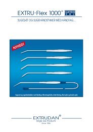
1 2<br />
60 +/- 10 mm<br />
Fig. 1.1.1Measurement set-up<br />
1 IR thermometer<br />
2 Heat exchanger<br />
(<strong>BW</strong> ring)<br />
Measuring instrument used: TESTO infrared thermometer QUICKTEMP 860-T2<br />
Accuracy: ±1%of reading or ±1°C<br />
Emission: 0,98<br />
November, 2007 <strong>BW</strong> Manufacture, Assembly, Test Documentation Page 15
2.READY FOR USE<br />
2.1 General<br />
•Start-up at 41 °C<br />
•Time how long it takes for the operating temperature of 40,5°C to be<br />
reached<br />
The initial temperature should be the same as the ambient temperature.<br />
The time taken must be less than 60 sec.<br />
For arrangement of heat exchanger and measuring instrument, see Fig.1.1.1<br />
3.OPERATING TEMPERATURE CHECK<br />
3.1 General<br />
The following checks must not be performed until the equipment has heated up<br />
(control circuits in steady state).<br />
The preliminary election of the temperature is 41 °C.<br />
The heat exchanger temperature should be 41 ±0.5°C with the display reading<br />
41°C.<br />
For arrangement of heat exchanger and measuring instrument, see Fig.1.1.1<br />
4.THERMAL PROTECTION CHECK - ELECTRONIC CUT-OFF<br />
4.1 General<br />
• switch on the warmer<br />
• preheat the device to 41°C and wait for the temperature to stabilize<br />
• remove the mains plug<br />
• hold down the ↑ control and reconnect the mains power plug<br />
• push the On/Standby switch (the device now heats up to a target<br />
temperature of 42,5 °C)<br />
• once it has cooled down, the equipment is ready for restart again<br />
• Observe the temperature indicator carefully; the high temperature alarm<br />
should be triggered at a temperature of 42°C. For reasons of safety, short<br />
beeping sounds are given at intervals of a second in this operational mode<br />
and the Led ON indicators flash alternately<br />
For arrangement of heat exchanger and measuring instrument, see Fig.1.1.1<br />
Page 16 <strong>BW</strong> Manufacture, Assembly, Test Documentation November, 2007
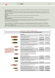
5.HIGH VOLTAGE TEST<br />
5.1 General<br />
Apply test voltage of 1.5 kV ~ to the heat exchanger for 1 min. The test must be<br />
performed on the <strong>BW</strong> <strong>585</strong> after operating temperature has been reached and<br />
with the equipment still in operation (see Fig.5.1.1)<br />
There must not be any flashovers or breakdowns during the test (slight corona<br />
discharge can be disregarded).<br />
Apply approx. 500 V to start with, then increase the voltage to the maximum<br />
value of 1.5 kV within 10 s (t = 1 minute).<br />
Finally reduce the voltage to the initial value.<br />
L1<br />
L2<br />
L3<br />
N 2<br />
1<br />
3<br />
1 Transformer<br />
2 Isol. Transformer<br />
3 Blood warmer<br />
Fig.: 5.1.1: Measuring circuit<br />
6. ELECTRICAL SAFETY<br />
6.1. General<br />
These tests must be carried out at operating temperature.<br />
(CAUTION: mains voltage)<br />
Perform the tests with Electrical Safety Tester GERB GM-100 and test program<br />
BLUTW 1. The report is stored in the computer.<br />
November, 2007 <strong>BW</strong> Manufacture, Assembly, Test Documentation Page 17
7. FUSE-LINKS<br />
7.1 General<br />
Check the fuse-links, especially during maintenance work. With this equipment,<br />
primary: <strong>BW</strong> <strong>585</strong> / 230V 1,6A slow<br />
<strong>BW</strong> <strong>585</strong> / 110V<br />
3,15A slow<br />
secondary: <strong>BW</strong> <strong>585</strong> / 230V / 110V 0,315A slow<br />
can be used.<br />
8. MECHANICAL CONDITION<br />
8.1 General<br />
The mechanical condition of the equipment (POWER CABLE) must allow<br />
further safe usage.<br />
9. SOILING<br />
9.1 General<br />
Ensure that there is no dirt on the equipment that could affect safety and check<br />
for any visible damage. Scratches or cracks that can be seen from a distance<br />
of approx. 40 cm must be recorded, the equipment switched off and withdrawn<br />
from service.<br />
10. LABELLING<br />
10.1 General<br />
Check that the nameplate and all labelling (earthing, power supply...) is legible<br />
and in good condition.<br />
Page 18 <strong>BW</strong> Manufacture, Assembly, Test Documentation November, 2007
INITIAL / MAINTENANCE INSPECTION<br />
SERIAL No.: ........................ DATE: .........................<br />
230V 110V PCB No.:..............................<br />
The tester must be familiar with the instructions before carrying out these tests !<br />
TEST<br />
1. Continuous test<br />
TARGET VALUE / FUNCTION<br />
Initial value:.......................°C<br />
ASSESMENT<br />
O.K<br />
n. O.K.<br />
2. Ready for use<br />
(at room temperature)<br />
3. Operating temp.<br />
Final value:.........................°C<br />
Actual value:........................s<br />
Actual value:.......................°C<br />
4. Overtemperature<br />
cut-off Target: < 42,5 °C<br />
5. High voltage<br />
6. Electrical safety<br />
7. Fuse-links<br />
8. Mech. conditions<br />
9. Soiling<br />
10. Labelling<br />
Target: 1,5 kV / 1 min<br />
Tester:<br />
November, 2007 <strong>BW</strong> Manufacture, Assembly, Test Documentation Page 19
<strong>BW</strong> <strong>585</strong><br />
Safety checks<br />
INTERVAL: every 12 months<br />
The following checks must be performed on this equipment at least every 12 months<br />
by persons who are capable of carrying out such safety checks as a result of their<br />
training, knowledge and practical experience .<br />
Test Target value/function Assessment Tester<br />
PE conductor resistance<br />
< 0.3 Ω<br />
OK<br />
not OK<br />
Back-up device leakage<br />
current<br />
< 0.75 mA<br />
Back up device leakage<br />
current<br />
first measured value<br />
............. mA<br />
The fuse-links must meet the manufacturer’s<br />
specifications (rated current, cut-off characteristics).<br />
The labelling relating to safety must be<br />
clearly visible on the equipment.<br />
The mechanical condition must allow<br />
further safe usage of the equipment.<br />
Soiling of the equipment must not<br />
affect safety.<br />
Page 20 <strong>BW</strong> Manufacture, Assembly, Test Documentation November, 2007
The performance checks listed in the operating instructions must also be carried<br />
out.<br />
The leakage current must not be greater than 1.5 times the first measured value<br />
and at the same time not greater than the above limit.<br />
If the equipment is not serviceable or safe to operate, it must be repaired or the<br />
User must be informed of the potential hazard.<br />
This is to certify that the above tests have been duly carried out and the<br />
recorded data is correct.<br />
Comments:<br />
Engineer<br />
User<br />
(Date, signature)<br />
(Date, signature)<br />
November, 2007 <strong>BW</strong> Manufacture, Assembly, Test Documentation Page 21
---------------------------------------------------------------------------<br />
GERB Elektronik GmbH<br />
Page 1 BLUTW1 Test Specifications Electrical Safety<br />
---------------------------------------------------------------------------<br />
Test Item Description<br />
---------------------------------------------------------------------------<br />
GERB024 Power measurement<br />
Effective power required by equipment is measured.<br />
Measurement time is limited and time-out is displayed.<br />
Maximum power 3.5 kVA.<br />
Ensure that <strong>BW</strong>385/<strong>BW</strong>385L is in warmup phase for test.<br />
Unit: Watt Target: 0.00 Limit: < 0.00 Abs. tol. 0.00 Rel. tol. 0.00<br />
Unit: Watt Target: 0.00 Limit: < 0.00 Abs. tol. 0.00 Rel. tol. 0.00<br />
GERB003 Insulation resistance power supply/PE<br />
Insulation test voltage 500 V= over 5 MOhm applied to both<br />
phases of equipment. Resistance between phases and<br />
PE conductor is measured.<br />
Equipment is in operating state (warm up first).<br />
Unit: MOhm Target: 0.00 Limit: > 2.00 Abs. tol. 0.00 Rel. tol. 0.00<br />
Unit: MOhm Target: 0.00 Limit: > 2.00 Abs. tol. 0.00 Rel. tol. 0.00<br />
GERB005 PE conductor resistance<br />
Insulation test voltage 6V max. 25A on test probe connection.<br />
Hold test probe on heater ring.<br />
Test time is limited.<br />
Time-out displayed on screen.<br />
Unit: Ohm Target: 0.00 Limit: < 0.30 Abs. tol. 0.00 Rel. tol. 0.00<br />
Unit: Ohm Target: 0.00 Limit: < 0.30 Abs. tol. 0.00 Rel. tol. 0.00<br />
GERB005 PE conductor resistance<br />
Insulation test voltage 6V max. 25A on test probe connection.<br />
Hold test probe on clip. Test time is limited.<br />
Time-out displayed on screen.<br />
Unit: Ohm Target: 0.00 Limit: < 0.30 Abs. tol. 0.00 Rel. tol. 0.00<br />
Unit: Ohm Target: 0.00 Limit: < 0.30 Abs. tol. 0.00 Rel. tol. 0.00<br />
GERB006 Earth leakage current NC<br />
Earth leakage current measured under operating conditions.<br />
Ensure that there is no other ground connector between GM100<br />
safety tester and equipment.<br />
No test probe required.<br />
Equipment in operating state (warm up first).<br />
Unit: uA Target: 0.00 Limit: < 500.00 Abs. tol. 0.00 Rel. tol. 0.00<br />
Unit: uA Target: 0.00 Limit: < 500.00 Abs. tol. 0.00 Rel. tol. 0.00<br />
GERB009 Housing leakage current SFC/PE open<br />
Hold test probe on clip.<br />
Ensure that there is no other ground connection to equipment.<br />
No test probe required.<br />
Equipment is in operating state (warm up first).<br />
Unit: uA Target: 0.00 Limit: < 500.00 Abs. tol. 0.00 Rel. tol. 0.00<br />
Unit: uA Target: 0.00 Limit: < 500.00 Abs. tol. 0.00 Rel. tol. 0.00<br />
Page 22 <strong>BW</strong> Manufacture, Assembly, Test Documentation November, 2007
Page 2 BLUTW1 Test Specifications Electrical Safety<br />
---------------------------------------------------------------------------<br />
Test Item Description<br />
---------------------------------------------------------------------------<br />
GERB019 Equivalent leakage current according to figure 9 (VDE 0751)<br />
Supply voltage is connected as insulation test voltage to mains<br />
connection of equipment. Current flowing from housing<br />
to earth is measured. Equivalent leakage current must not<br />
be greater than 1.5 times first measured value and no greater<br />
than limit value of 0.75 mA.<br />
Equipment is in operating state (warm up first).<br />
Unit: uA Target: 0.00 Limit: < 750.00 Abs. tol. 0.00 Rel. tol. 0.00<br />
Unit: uA Target: 0.00 Limit: < 750.00 Abs. tol. 0.00 Rel. tol. 0.00<br />
GERB020 Equivalent equipment leakage current in PE conductor<br />
to VDE 751<br />
Internally generated insulation test voltage equivalent to<br />
supply voltage is applied to equipment mains connections.<br />
Current flowing from PE conductor to earth is measured.<br />
Equipment is in operating state (warm up first).<br />
Equivalent equipment leakage current must not be greater<br />
than 1.5 times first measured value and no greater than limit<br />
value of 0.75 mA.<br />
Unit: uA Target: 0.00 Limit: < 750.00 Abs. tol. 0.00 Rel. tol. 0.00<br />
Unit: uA Target: 0.00 Limit: < 750.00 Abs. tol. 0.00 Rel. tol. 0.00<br />
GERB021 Equivalent equipment leakage current to VDE 751<br />
Internally generated insulation test voltage equivalent to<br />
supply voltage is applied to equipment mains connections.<br />
Current flowing from housing to earth is measured.<br />
Equipment is in operating state (warm up first).<br />
Hold GM tester probe on clip of equipment under test.<br />
Equivalent equipment leakage current must not be greater<br />
than 1.5 times first measured value and no greater than limit<br />
value of 0.75 mA.<br />
Unit: uA Target: 0.00 Limit: < 750.00 Abs. tol. 0.00 Rel. tol. 0.00<br />
Unit: uA Target: 0.00 Limit: < 750.00 Abs. tol. 0.00 Rel. tol. 0.00<br />
GERB001 Supply voltage test<br />
Effective supply voltage is measured.<br />
Unit: Volt Target: 220.00 Limit: > 200.00 Abs. tol. 0.00 Rel. tol. 0.00<br />
Unit: Volt Target: 220.00 Limit: > 200.00 Abs. tol. 0.00 Rel. tol. 0.00<br />
November, 2007 <strong>BW</strong> Manufacture, Assembly, Test Documentation Page 23
MASTER PARTS / SPARE PARTS<br />
<strong>BW</strong> <strong>585</strong> V 1.6<br />
Description<br />
Part No.<br />
Set of foils <strong>BW</strong> <strong>585</strong> FV 6000014<br />
Head piece HB 1008021<br />
Roods, 2 pcs. needed HA 1002201<br />
Ground bracket HA 1002012<br />
PCB Keyboard V1 IP 1000586<br />
PCB Main complete V 1.6 IP 2002020<br />
Heat exchanger <strong>BW</strong> <strong>585</strong> complete with sensor <strong>BW</strong> <strong>585</strong> and heating IR 1002586<br />
band<br />
Silicon cord 1,10 meter HB 2002001<br />
Plastic collar HB 3002200<br />
Rear panel complete IR 1002<strong>585</strong><br />
Clamp complete with twist knob left and right IK 9002228<br />
Twist knob - right HA 1002208<br />
Twist knob - left HA 1002108<br />
Power cord with strain relief KN 1002001<br />
Page 24 <strong>BW</strong> Manufacture, Assembly, Test Documentation November, 2007