
Create successful ePaper yourself
Turn your PDF publications into a flip-book with our unique Google optimized e-Paper software.
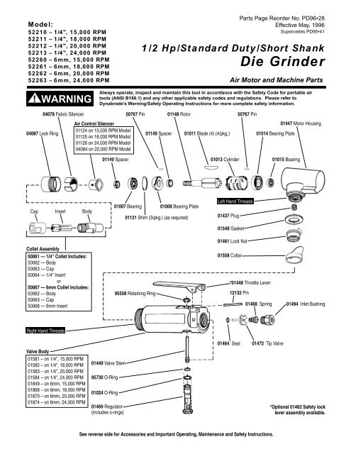
Model:<br />
52210 – 1/4", 15,000 RPM<br />
52211 – 1/4", 18,000 RPM<br />
52212 – 1/4", 20,000 RPM<br />
52213 – 1/4", 24,000 RPM<br />
52260 – 6mm, 15,000 RPM<br />
52261 – 6mm, 18,000 RPM<br />
52262 – 6mm, 20,000 RPM<br />
52263 – 6mm, 24,000 RPM<br />
Parts Page Reorder No. PD96•28<br />
Effective May, 1996<br />
Supercedes PD95•41<br />
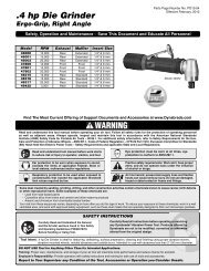
1/2 Hp/Standard Duty/Short Shank<br />
<strong>Die</strong> <strong>Grinder</strong><br />
Air Motor and Machine Parts<br />
!<br />
WARNING<br />
Always operate, inspect and maintain this tool in accordance with the Safety Code for portable air<br />
tools (ANSI B186.1) and any other applicable safety codes and regulations. Please refer to<br />
<strong>Dynabrade</strong>'s Warning/Safety Operating Instructions for more complete safety information.<br />
04087 Lock Ring<br />
04078 Fabric Silencer<br />
Air Control Silencer<br />
01124 on 15,000 RPM Model<br />
01125 on 18,000 RPM Model<br />
01126 on 24,000 RPM Model<br />
04084 on 20,000 RPM Model<br />
50767 Pin<br />
01149 Spacer<br />
01148 Rotor<br />
01011 Blade (4) (4/pkg.)<br />
50767 Pin<br />
01014 Bearing Plate<br />
01447 Motor Housing<br />
01149 Spacer<br />
01013 Cylinder<br />
01015 Bearing<br />
Cap<br />
Insert<br />
Body<br />
01007 Bearing<br />
01008 Bearing Plate<br />
01121 Shim (3/pkg.) (as required)<br />
Left Hand Threads<br />
01437 Plug<br />
01548 Gasket<br />
Collet Assembly<br />
50061 — 1/4" Collet <strong>Inc</strong>ludes:<br />
50062 — Body<br />
50063 — Cap<br />
50064 — 1/4" Insert<br />
or<br />
50067 — 6mm Collet <strong>Inc</strong>ludes:<br />
50062 — Body<br />
50063 — Cap<br />
50068 — 6mm Insert<br />
95558 Retaining Ring<br />
01461 Lock Nut<br />
01558 Collar<br />
*01448 Throttle Lever<br />
12132 Pin<br />
01468 Spring<br />
01494 Inlet Bushing<br />
Right Hand Threads<br />
Valve Body<br />
01581 – on 1/4", 15,000 RPM<br />
01582 – on 1/4", 18,000 RPM<br />
01583 – on 1/4", 20,000 RPM<br />
01584 – on 1/4", 24,000 RPM<br />
01849 – on 6mm, 15,000 RPM<br />
01868 – on 6mm, 18,000 RPM<br />
01870 – on 6mm, 20,000 RPM<br />
01874 – on 6mm, 24,000 RPM<br />
01449 Valve Stem<br />
95730 O-Ring<br />
01024 O-Ring<br />
01469 Regulator<br />
(includes o-rings)<br />
01464 Seal<br />
01472 Tip Valve<br />
*Optional 01462 Safety lock<br />
lever assembly available.<br />
See reverse side for Accessories and Important Operating, Maintenance and Safety Instructions.
Disassembly/Assembly Instructions-.5 Hp/7°/Front Exhaust<br />
Important: Manufactures warranty is void if tool is disassembled before warranty expires.<br />
Please refer to parts breakdown for part identification.<br />
To Disassemble:<br />
1. Secure air tool in vise using or padded jaws.<br />
2. Remove collet cap and insert.<br />
3. With an adjustable pin wrench, remove 04087 Lock Ring by turning counter-clockwise. Remove air control silencer and fabric silencer.<br />
4. Pull motor assembly from housing.<br />
5. Reposition motor housing in vise so inlet bushing is facing upwards.<br />
6. Unscrew 01494 Inlet Bushing turning counter-clockwise.<br />
7. Using needle nose pliers, remove 01468 Spring, 01472 Tip Valve and 01464 Seal.<br />
8. Resecure housing in vise so throttle lever and 12132 Pin are accessible.<br />
9. Using a 2.5 mm diameter drift pin and a hammer, tap 12132 Pin out from housing and remove throttle lever.<br />
10. Remove 95558 Retaining Ring and push 01469 Speed Regulator from Housing.<br />
Optional: To disassemble valve body from motor housing, peel back 01558 Collar to expose 01462 Lock Nut. Unscrew lock nut/valve body from housing<br />
(left hand threads).<br />
Motor Disassembly:<br />
1. Remove 50062 Collet Body from rotor shaft by inserting 3/16" hex wrench through collet body and into rotor shaft. Twist collet body from shaft.<br />
2. Remove 01008 Front Bearing Plate, cylinder, blades (4) and 01149 Spacer from rotor.<br />
Note: 01007 Bearing, 01008 Front Bearing Plate and 01149 Spacer are a slip fit onto rotor.<br />
3. Press rotor from 01014 Rear Bearing Plate. Press 01015 Bearing from bearing plate.<br />
Motor disassembly is complete.<br />
Motor Reassembly<br />
Important: Be sure parts are clean and in good repair before reassembly<br />
1. Place rotor in padded vise with a threaded spindle facing upwards.<br />
2. Slip 01149 Spacer onto rotor.<br />
3. Place a .002" shim into 01008 Front Bearing Plate as an initial spacing (Note: 01121 Shim Pak contains .001" and .002" shims) and slip 01007<br />
Bearing into plate.<br />
4. Install Bearing/Bearing Plate assembly onto rotor.<br />
5. Tighten 50062 Collet Body onto rotor (torque to 150 in. - lbs.).<br />
6. Check clearance between rotor and bearing plate by using a .001" feeler gauge. Clearance should be at .001" to .0015". Adjust clearance by repeating<br />
steps 1-5 with different shim if necessary.<br />
7. Once proper rotor/gap clearance is achieved, install well lubricated 01011 Blades (4) into rotor slots. <strong>Dynabrade</strong> air lube P/N 95842 is recommended<br />
for lubrication.<br />
8. Install cylinder over rotor. Be sure air inlet holes of cylinder face away from bearing plate.<br />
9. Press 01015 Rear Bearing into 01014 Rear Bearing Plate. Press bearing/bearing plate assembly onto rotor. Be sure that pin and air inlet holes line-up with pin slot<br />
and air inlet holes in cylinder.<br />
Important: Fit must be snug between bearing plates and cylinder. If too tight, rotor will not turn freely. Rotor must then be lightly tapped at press fit end so it<br />
will turn freely while still maintaining a snug fit. A loose fit will not achieve the proper preload of motor bearings.<br />
10. Secure motor housing in padded vise so motor cavity faces upwards.<br />
11. Install motor assembly into housing. Be sure motor drops all the way into housing.<br />
12. Insert air control silencer and fabric silencer into 04087 Lock Ring and install onto motor housing (torque 150 in. - lbs.).<br />
13. Motor adjustment must now be checked. With motor housing still mounted in vise, pull end of rotor and twist (10-15 lbs. force), rotor should turn freely<br />
without drag. If drag or rub is felt, then increase preload or remove shim. Also, push end of rotor and twist (10-15 lbs. force), rotor should turn freely<br />
without drag. If drag or rub is felt, then deload or add shim.<br />
Valve Stem/Body Reassembly:<br />
1. Insert 01469 Speed Regulator Assembly into valve body. Secure with 95558 Retaining Ring.<br />
2. Secure valve body in vise using padded jaws with air inlet facing upwards and throttle lever accessible.<br />
3. Insert 01464 Seal into housing.<br />
4. Line-up the hole in the 01449 Valve Stem with the hole in the housing (looking past brass bushing). Using needle nose pliers, insert 01472 Tip Valve so<br />
that the metal pin passes through the hole in the valve stem.<br />
5. Install 01468 Spring (small end towards the tip valve).<br />
6. Apply 1 drop of #271 Loctite (or equivalent) to threads of 01494 Inlet Bushing and install into valve body (torque 34.0 N•m 200 lbs. in.).<br />
7. Install throttle lever and 12132 Pin. Remove valve body from vise.<br />
Tool Assembly is complete. Please allow 30 minutes for adhesives to cure before operating tool.<br />
Important: Motor should now be tested for proper operation at 90 PSI. If motor does not operate properly or operates at a higher RPM than marked on the<br />
tool, the tool should be serviced to correct the cause before use.<br />
Note: Throttle lever is preset at the factory at an 11:00 o’clock position.<br />
Loctite® is a registered trademark of Loctite Corp.<br />
3
Optional Accessories<br />
53032 — 1/4" Drill Chuck<br />
<strong>Inc</strong>ludes: 53052 Mated Chuck Key<br />
Collet Inserts<br />
• 50065 — 1/8"<br />
• 50039 — 8mm<br />
Dynaswivel®<br />
Swivels 360° at two locations which<br />
allows an air hose to drop straight to<br />
the floor, no matter how the tool is held.<br />
• 95460 1/4" NPT<br />
96039 Motor Tune-Up Kit:<br />
• <strong>Inc</strong>ludes assorted parts to help maintain<br />
motor in tip-top shape.<br />
Wrenches<br />
95281 – 19 mm open-end<br />
95262 – 14 mm open-end<br />
Important Operating, Maintenance and Safety Instructions<br />
Carefully read all instructions before operating or servicing any <strong>Dynabrade</strong>® Abrasive Power Tool.<br />
Warning: Hand, wrist and arm injury may result from repetitive work motion and overexposure to vibration.<br />
Important: All <strong>Dynabrade</strong> air tools must be used with a Filter-Regulator-Lubricator to maintain all warranties.<br />
Operating Instructions:<br />
Warning: Eye, face and body protection must be worn while operating power tools. Failure to do so may result in serious injury or death. Follow safety<br />
procedures posted in workplace.<br />
1. With power source disconnected from tool, securely fasten abrasive/accessory on tool.<br />
2. Connect power source to tool. Be careful not to depress throttle lever in the process.<br />
3. Check tool speed with tachometer. If tool is operating at a higher speed than the RPM marked on the tool or operating improperly, the tool should be<br />
serviced to correct the cause before use.<br />
Maintenance Instructions:<br />
Products offered by <strong>Dynabrade</strong> should not be converted or otherwise altered from original design without expressed written consent<br />
from <strong>Dynabrade</strong>, <strong>Inc</strong>.<br />
1. Check tool speed regularly with a tachometer. If tool is operating at a higher speed than the RPM marked on the tool, the tool should be serviced to correct<br />
the cause before use.<br />
2. Some silencers on air tools may clog with use. Clean and replace as required.<br />
3. All <strong>Dynabrade</strong> air motors should be lubricated with two drops of <strong>Dynabrade</strong> Air Lube (P/N 95842: 1pt. 473ml.) every four hours of use.<br />
4. An air line filter-regulator-lubricator must be used with this air tool to maintain all warranties. <strong>Dynabrade</strong> recommends the following: 11289 Air Line Filter-<br />
Regulator-Lubricator — Provides accurate air pressure regulation, two-stage filtration of water contaminants and micro-mist lubrication of pneumatic<br />
components. Operates 40 CFM @ 90 PSI has 3/8" NPT female ports.<br />
Safety Instructions:<br />
• Important: User of tool is responsible for following accepted safety codes such as those published by the American National Standards Institute (ANSI).<br />
• Operate machine for one minute before application to workpiece to determine if machine is working properly and safely before work begins.<br />
• Always disconnect power supply before changing abrasive or making machine adjustments.<br />
• Inspect abrasives/accessories for damage or defects prior to installation on tools.<br />
• Please refer to <strong>Dynabrade</strong>’s Warning/Safety Operating Instructions Tag (Reorder No. 95903) for more complete safety information.<br />
• Warning: Hand, wrist and arm injury may result from repetitive work, motion and overexposure to vibration.<br />
Full One Year Warranty<br />
Following the reasonable assumption that any inherent defect which might prevail in a product will become apparent to the user within one year from<br />
the date of purchase, all equipment of our manufacture is warranted against defects in workmanship and materials under normal use and service. We shall<br />
repair or replace at our factory, any equipment or part thereof which shall, within one year after delivery to the original purchaser, indicate upon our<br />
examination to have been defective. Our obligation is contingent upon proper use of <strong>Dynabrade</strong> tools in accordance with factory recommendations,<br />
instructions and safety practices. It shall not apply to equipment which has been subject to misuse, negligence, accident or tampering in any way so as to affect<br />
its normal performance. Normally wearable parts such as bearings, sanding pads, rotor blades, etc., are not covered under this warranty.<br />
2
DYNABRADE ®<br />
Toll Free (U.S.A.) 1-800-828-7333<br />
Toll Free (Can.) 1-800-344-1488<br />
DYNABRADE, INC., 8989 Sheridan Drive • Clarence, NY 14031-1490 • Phone: (716) 631-0100 • Fax: 716-631-2073 • International Fax: 716-631-2524<br />
DYNABRADE EUROPE S.àr.l., Zone Artisanale • L-5485 Wormeldange—Haut, Luxembourg • Telephone: 352 76 84 94 • Fax: 352 76 84 95<br />
© DYNABRADE, INC., 1996 PRINTED IN USA