vtec air flow converterⅱ wiring diagram by model - APEXi USA
vtec air flow converterⅱ wiring diagram by model - APEXi USA
vtec air flow converterⅱ wiring diagram by model - APEXi USA

You also want an ePaper? Increase the reach of your titles
YUMPU automatically turns print PDFs into web optimized ePapers that Google loves.
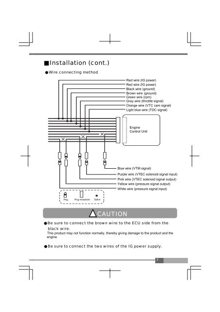
Installation (cont.)<br />
Wire connecting method<br />
Red wire (IG power)<br />
Red wire (IG power)<br />
Black wire (ground)<br />
Brown wire(ground)<br />
Green wire (rpm)<br />
Gray wire (throttle signal)<br />
Orange wire (VTC cam signal)<br />
Light blue wire (TDC signal)<br />
Engine<br />
Control Unit<br />
Blue wire (VTM signal)<br />
Purple wire (VTEC solenoid signal input)<br />
Pink wire (VTEC solenoid signal output)<br />
Yellow wire (pressure signal output)<br />
White wire (pressure signal input)<br />
Plug Plug receptacle Splice<br />
CAUTION<br />
Be sure to connect the brown wire to the ECU side from the<br />
black wire.<br />
This product may not function normally, there<strong>by</strong> giving damage to the product and the<br />
engine.<br />
<br />
Besuretoconnect the twowires of the IGpower supply.