Conventional Machining Methods for Rapid Prototyping
Conventional Machining Methods for Rapid Prototyping
Conventional Machining Methods for Rapid Prototyping

You also want an ePaper? Increase the reach of your titles
YUMPU automatically turns print PDFs into web optimized ePapers that Google loves.
10<br />
Z. Yang, R. A. Wysk, S. Joshi, M. C. Frank ,and J. E. Petrzelka<br />
The rapid machining process is based on a setup strategy whereby a rotary device<br />
is used to rotate round stock material that is fixed between two opposing chucks. Rotating<br />
the stock using an indexer eliminates the inherent problem of retaining reference<br />
coordinates associated with re-clamping a part in a conventional fixture. For each<br />
orientation, all visible surfaces are machined and the sacrificial supports keep it<br />
connected to the uncut ends of the stock material. Once all operations are complete, the<br />
supports are severed (sawed or milled) in a final series of operations, and the part is<br />
removed. Post-processing is per<strong>for</strong>med to finish the minimal support contact patches on<br />
the part.<br />
The setup and steps to this approach are shown in Figure 7 and Figure 9,<br />
respectively. As an example in Figure 9, a component is being machined using sacrificial<br />
supports to retain the part at its ends along the axis of rotation. CNC-RP employed this<br />
setup and process planning strategy in previous work as a method <strong>for</strong> rapid machining.<br />
Sacrificial support fixtures have been designed manually and used in several proof-ofconcept<br />
parts. This method of using one axis of rotation <strong>for</strong> indexing between setups is<br />
obviously not capable of machining all parts of extremely complex shape. Parts with<br />
severely undercut features or complex features on three or more mutually orthogonal<br />
faces may not be machinable with this approach. In particular, this setup strategy<br />
assumes that some axis of rotation exists such that all surfaces are visible.<br />
Figure 7 Set up <strong>for</strong> CNC-RP(Frank 2003)<br />
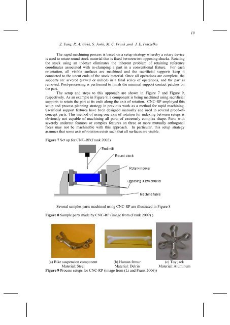
Several samples parts machined using CNC-RP are illustrated in Figure 8<br />
Figure 8 Sample parts made by CNC-RP (image from (Frank 2009) )<br />
(a) Bike suspension component<br />
Material: Steel<br />
(b) Human femur<br />
Material: Delrin<br />
(c) Toy jack<br />
Material: Aluminum<br />
Figure 9 Process setups <strong>for</strong> CNC-RP (image from (Li and Frank 2006))